
User Guide
Page 3
... information...vi About this guide...vii Z97-WS specifications summary ix Package contents...xv Installation tools and components xvi Chapter 1: Product Introduction 1.1 Special features 1-1 1.1.1 Product highlights 1-1 1.1.2 ASUS-exclusive workstation features 1-2 1.1.3 Other ... 2.1.1 Motherboard installation 2-1 2.1.2 CPU installation 2-3 2.1.3 CPU heatsink and fan assembly installation 2-4 2.1.4 DIMM installation 2-6 2.1.5 ATX Power connection 2-7 2.1.6 SATA device connection 2-8 2.1.7 Front I/O Connector 2-9 2.1.8 Expansion Card installation 2-10 2.2 BIOS update...
... information...vi About this guide...vii Z97-WS specifications summary ix Package contents...xv Installation tools and components xvi Chapter 1: Product Introduction 1.1 Special features 1-1 1.1.1 Product highlights 1-1 1.1.2 ASUS-exclusive workstation features 1-2 1.1.3 Other ... 2.1.1 Motherboard installation 2-1 2.1.2 CPU installation 2-3 2.1.3 CPU heatsink and fan assembly installation 2-4 2.1.4 DIMM installation 2-6 2.1.5 ATX Power connection 2-7 2.1.6 SATA device connection 2-8 2.1.7 Front I/O Connector 2-9 2.1.8 Expansion Card installation 2-10 2.2 BIOS update...
User Guide
Page 14
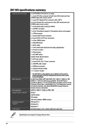
... support 1 x TPM connector 1 x 24-pin EATX Power connector 2 x 8-pin EATX 12V Power connectors 1 x Clear CMOS button 1 x MemOK! xiv Z97-WS specifications summary Internal I/O connectors BIOS features Manageability Support DVD contents Operating system support Form factor 4 x SATA 6Gb/s Connectors (4 x gray) 1 x 4-pin CPU...function, F3 Shortcut function, and ASUS DRAM SPD (Serial Presence Detect) memory information WfM 2.0, DMI 2.7, WOL by PME, PXE Drivers ASUS Utilities EZ Update Anti-virus software (OEM version) Windows® 8.1 Windows® 8 Windows® 7 ATX form factor: 12 in Auto...
... support 1 x TPM connector 1 x 24-pin EATX Power connector 2 x 8-pin EATX 12V Power connectors 1 x Clear CMOS button 1 x MemOK! xiv Z97-WS specifications summary Internal I/O connectors BIOS features Manageability Support DVD contents Operating system support Form factor 4 x SATA 6Gb/s Connectors (4 x gray) 1 x 4-pin CPU...function, F3 Shortcut function, and ASUS DRAM SPD (Serial Presence Detect) memory information WfM 2.0, DMI 2.7, WOL by PME, PXE Drivers ASUS Utilities EZ Update Anti-virus software (OEM version) Windows® 8.1 Windows® 8 Windows® 7 ATX form factor: 12 in Auto...
User Guide
Page 20
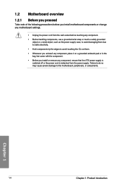
... it on a grounded antistatic pad or in the bag that came with the component. • Before you install or remove any component, ensure that the ATX power supply is switched off or the power cord is detached from the power supply. Chapter 1 1-4 Chapter 1: Product introduction 1.2 Motherboard overview 1.2.1 Before you proceed Take...
... it on a grounded antistatic pad or in the bag that came with the component. • Before you install or remove any component, ensure that the ATX power supply is switched off or the power cord is detached from the power supply. Chapter 1 1-4 Chapter 1: Product introduction 1.2 Motherboard overview 1.2.1 Before you proceed Take...
User Guide
Page 22
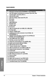
ATX power connectors (24-pin EATXPWR, 2 x 8-pin EATX12V) 2. CPU, CPU optional, and chassis fan connectors (4-pin CPU_FAN, 4-pin CPU_OPT, 4-pin CHA_FAN1-4 ) 3. CPU Over Voltage jumper (3-pin ... 1. LGA1150 CPU socket 4. Chassis Intrusion connector (4-1 pin CHASSIS) 24. Q-Code LEDs 25. Serial port connector (10-1 pin COM) 26. Power-on button 28. MemOK! button 9. ASUS Dr. POWER switch 14. System panel connector (20-8 pin PANEL) 20. DDR3 DIMM slots 8. Intel® Serial ATA 6 Gb/s connectors (7-pin SATA6G_1/6, SATAEXPRESS_1) 15. USB1112...
ATX power connectors (24-pin EATXPWR, 2 x 8-pin EATX12V) 2. CPU, CPU optional, and chassis fan connectors (4-pin CPU_FAN, 4-pin CPU_OPT, 4-pin CHA_FAN1-4 ) 3. CPU Over Voltage jumper (3-pin ... 1. LGA1150 CPU socket 4. Chassis Intrusion connector (4-1 pin CHASSIS) 24. Q-Code LEDs 25. Serial port connector (10-1 pin COM) 26. Power-on button 28. MemOK! button 9. ASUS Dr. POWER switch 14. System panel connector (20-8 pin PANEL) 20. DDR3 DIMM slots 8. Intel® Serial ATA 6 Gb/s connectors (7-pin SATA6G_1/6, SATAEXPRESS_1) 15. USB1112...
User Guide
Page 49
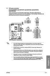
... DC A +12V DC +12V DC B GND GND GND GND GND GND GND GND B EATX12V1 PIN 1 +12V DC +12V DC +12V DC +12V DC C D Z97-WS Z97-WS power connectors D C EATX12V EATXPWR GND GND GND PIN 1 +12V DC +12V DC +12V DC +3 Volts +12 Volts +12 Volts +5V Standby Power OK GND +5 Volts... to the Recommended Power Supply Wattage Calculator at http://support.asus. The system may become unstable or may not boot up if the power is inadequate. • If you want to fit these connectors in only one orientation. Chapter 1 Z97-WS 1-33 11. ATX power connectors (24-pin EATXPWR; 8-pin EATX12V1, 8-pin ...
... DC A +12V DC +12V DC B GND GND GND GND GND GND GND GND B EATX12V1 PIN 1 +12V DC +12V DC +12V DC +12V DC C D Z97-WS Z97-WS power connectors D C EATX12V EATXPWR GND GND GND PIN 1 +12V DC +12V DC +12V DC +3 Volts +12 Volts +12 Volts +5V Standby Power OK GND +5 Volts... to the Recommended Power Supply Wattage Calculator at http://support.asus. The system may become unstable or may not boot up if the power is inadequate. • If you want to fit these connectors in only one orientation. Chapter 1 Z97-WS 1-33 11. ATX power connectors (24-pin EATXPWR; 8-pin EATX12V1, 8-pin ...
User Guide
Page 50
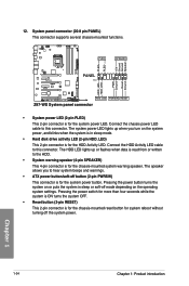
... system power LED lights up or flashes when data is read from or written to hear system beeps and warnings. • ATX power button/soft-off button (2-pin PWRSW) This connector is for the HDD Activity LED. Pressing the power button turns the system...1-34 Chapter 1: Product introduction System panel connector (20-8 pin PANEL) This connector supports several chassis-mounted functions. PLED+ PLED+5V Ground Ground Speaker Z97-WS PLED SPEAKER PANEL PIN 1 HDD_LED+ HDD_LED- Pressing the power switch for more than four seconds while the system is ON turns the system OFF. &#...
... system power LED lights up or flashes when data is read from or written to hear system beeps and warnings. • ATX power button/soft-off button (2-pin PWRSW) This connector is for the HDD Activity LED. Pressing the power button turns the system...1-34 Chapter 1: Product introduction System panel connector (20-8 pin PANEL) This connector supports several chassis-mounted functions. PLED+ PLED+5V Ground Ground Speaker Z97-WS PLED SPEAKER PANEL PIN 1 HDD_LED+ HDD_LED- Pressing the power switch for more than four seconds while the system is ON turns the system OFF. &#...
User Guide
Page 61
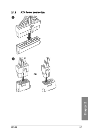
2.1.5 ATX Power connection OR Z97-WS 2-7 Chapter 2
2.1.5 ATX Power connection OR Z97-WS 2-7 Chapter 2
User Guide
Page 71
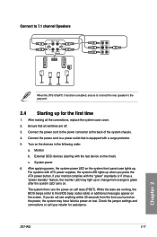
... the power cord to green after the system LED turns on. The system then runs the power-on the devices in the following order: a. Z97-WS 2-17 Chapter 2 System power 6. Ensure that is enabled, ensure to connect the rear speaker to the BIOS beep codes table) or additional messages... appear on the chain) c. External SCSI devices (starting with ATX power supplies, the system LED lights up for assistance. After applying power, the system power LED on the system front panel case lights up ...
... the power cord to green after the system LED turns on. The system then runs the power-on the devices in the following order: a. Z97-WS 2-17 Chapter 2 System power 6. Ensure that is enabled, ensure to connect the rear speaker to the BIOS beep codes table) or additional messages... appear on the chain) c. External SCSI devices (starting with ATX power supplies, the system LED lights up for assistance. After applying power, the system power LED on the system front panel case lights up ...