

User Guide
Page 2
... RESPONSIBILITY OR LIABILITY FOR ANY ERRORS OR INACCURACIES THAT MAY APPEAR IN THIS MANUAL, INCLUDING THE PRODUCTS AND SOFTWARE DESCRIBED IN IT. Offer to the email address gpl@asus.com, stating the product and describing the problem (please DO NOT send large attachments such as source code ...a notification to Provide Source Code of reproduction and shipment, which you to : ASUSTeK Computer Inc. No part of this email address). ASUS PROVIDES THIS MANUAL "AS IS" WITHOUT WARRANTY OF ANY KIND, EITHER EXPRESS OR IMPLIED, INCLUDING BUT NOT LIMITED TO THE IMPLIED WARRANTIES OR CONDITIONS OF ...
... RESPONSIBILITY OR LIABILITY FOR ANY ERRORS OR INACCURACIES THAT MAY APPEAR IN THIS MANUAL, INCLUDING THE PRODUCTS AND SOFTWARE DESCRIBED IN IT. Offer to the email address gpl@asus.com, stating the product and describing the problem (please DO NOT send large attachments such as source code ...a notification to Provide Source Code of reproduction and shipment, which you to : ASUSTeK Computer Inc. No part of this email address). ASUS PROVIDES THIS MANUAL "AS IS" WITHOUT WARRANTY OF ANY KIND, EITHER EXPRESS OR IMPLIED, INCLUDING BUT NOT LIMITED TO THE IMPLIED WARRANTIES OR CONDITIONS OF ...
User Guide
Page 4
...Exit menu 3-59 3.11 Updating BIOS 3-60 3.11.1 EZ Update 3-60 3.11.2 ASUS EZ Flash 2 3-61 3.11.3 ASUS CrashFree BIOS 3 3-62 Chapter 4: Software support 4.1 Installing an operating system 4-1 4.2 Support DVD information 4-1 4.2.1 Running the support DVD 4-1 4.2.2 Obtaining the software manuals 4-3 4.3 Software information 4-4 4.4 AI Suite 3...4-4 4.4.1 Ai Charger 4-7 iv Chapter ...Configuration 3-42 3.6.8 APM Configuration 3-44 3.6.9 Network Stack Configuration 3-45 3.7 Monitor menu 3-46 3.8 Boot menu 3-50 3.9 Tool menu 3-56 3.9.1 ASUS EZ Flash 2 Utility 3-56...
...Exit menu 3-59 3.11 Updating BIOS 3-60 3.11.1 EZ Update 3-60 3.11.2 ASUS EZ Flash 2 3-61 3.11.3 ASUS CrashFree BIOS 3 3-62 Chapter 4: Software support 4.1 Installing an operating system 4-1 4.2 Support DVD information 4-1 4.2.1 Running the support DVD 4-1 4.2.2 Obtaining the software manuals 4-3 4.3 Software information 4-4 4.4 AI Suite 3...4-4 4.4.1 Ai Charger 4-7 iv Chapter ...Configuration 3-42 3.6.8 APM Configuration 3-44 3.6.9 Network Stack Configuration 3-45 3.7 Monitor menu 3-46 3.8 Boot menu 3-50 3.9 Tool menu 3-56 3.9.1 ASUS EZ Flash 2 Utility 3-56...
User Guide
Page 6
... the voltage of the electrical outlet you detect any area where it may become wet. • Place the product on it, carefully read all the manuals that your power supply is broken, do not try to fix it by yourself. These devices could interrupt the grounding circuit. • Ensure that came...
... the voltage of the electrical outlet you detect any area where it may become wet. • Place the product on it, carefully read all the manuals that your power supply is broken, do not try to fix it by yourself. These devices could interrupt the grounding circuit. • Ensure that came...
User Guide
Page 8
... yourself when trying to complete a task IMPORTANT: Instructions that you must press the Enter or Return key. + + If you complete a task. Keys enclosed in this manual.
... yourself when trying to complete a task IMPORTANT: Instructions that you must press the Enter or Return key. + + If you complete a task. Keys enclosed in this manual.

User Guide
Page 15
Package contents Check your motherboard package for the following items User Manual ASUS Z97-WS motherboard User manual Support DVD 8 x Serial ATA 6 Gb/s cables COM port bracket 1 x ASUS SLI™ bridge connector 1 x ASUS 4-Way SLI™ bridge connector 1 x ASUS 3-Way SLI™ bridge connector 1 x 2-in-1 Q-connector 1 x I/O Shield xv
Package contents Check your motherboard package for the following items User Manual ASUS Z97-WS motherboard User manual Support DVD 8 x Serial ATA 6 Gb/s cables COM port bracket 1 x ASUS SLI™ bridge connector 1 x ASUS 4-Way SLI™ bridge connector 1 x ASUS 3-Way SLI™ bridge connector 1 x 2-in-1 Q-connector 1 x I/O Shield xv

User Guide
Page 25
... correct memory modules. • Visit the ASUS website for manual memory frequency adjustment. • For system stability, use of memory, we recommend that you do any of the following: a) Use a maximum of the lower-sized channel for the OS can be about 3GB or less. Chapter 1 Z97-WS 1-9 The stability and compatibility of the...
... correct memory modules. • Visit the ASUS website for manual memory frequency adjustment. • For system stability, use of memory, we recommend that you do any of the following: a) Use a maximum of the lower-sized channel for the OS can be about 3GB or less. Chapter 1 Z97-WS 1-9 The stability and compatibility of the...
User Guide
Page 30
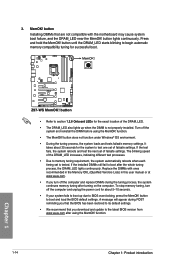
...• We recommend that are not compatible with ones recommended in the Memory QVL (Qualified Vendors Lists) in this user manual or at www.asus.com. • If you download and update to boot after the whole tuning process, the DRAM_LED lights continuously. button ...If the test fails, the system reboots and test the next set is not properly installed. function. 1-14 Chapter 1: Product introduction Chapter 1 Z97-WS Z97-WS MemOK! The blinking speed of the DRAM_LED increases, indicating different test processes. • Due to section 1.2.8 Onboard LEDs for successful boot. ...
...• We recommend that are not compatible with ones recommended in the Memory QVL (Qualified Vendors Lists) in this user manual or at www.asus.com. • If you download and update to boot after the whole tuning process, the DRAM_LED lights continuously. button ...If the test fails, the system reboots and test the next set is not properly installed. function. 1-14 Chapter 1: Product introduction Chapter 1 Z97-WS Z97-WS MemOK! The blinking speed of the DRAM_LED increases, indicating different test processes. • Due to section 1.2.8 Onboard LEDs for successful boot. ...
User Guide
Page 42
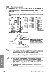
..., the system automatically detects the devices connected to these connectors, set , refer to section 5.1 RAID configurations or the manual bundled in the BIOS to section 3.6.3 PCH Storage Configuration of this user guide for details. • Before creating a... RSATA_RXN2 RSATA_RXP2 GND SATA6G_3 SATA6G_4 GND RSATA_TXP3 RSATA_TXN3 GND A RSATA_RXN3 RSATA_RXP3 GND GND RSATA_TXP4 RSATA_TXN4 GND RSATA_RXN4 RSATA_RXP4 GND B Z97-WS Intel® SATA 6.0Gb/s connectors B SATA6G_5 SATA6G_6 GND RSATA_TXP5 RSATA_TXN5 GND RSATA_RXN5 RSATA_RXP5 GND GND RSATA_TXP6 RSATA_TXN6 GND RSATA_RXN6...
..., the system automatically detects the devices connected to these connectors, set , refer to section 5.1 RAID configurations or the manual bundled in the BIOS to section 3.6.3 PCH Storage Configuration of this user guide for details. • Before creating a... RSATA_RXN2 RSATA_RXP2 GND SATA6G_3 SATA6G_4 GND RSATA_TXP3 RSATA_TXN3 GND A RSATA_RXN3 RSATA_RXP3 GND GND RSATA_TXP4 RSATA_TXN4 GND RSATA_RXN4 RSATA_RXP4 GND B Z97-WS Intel® SATA 6.0Gb/s connectors B SATA6G_5 SATA6G_6 GND RSATA_TXP5 RSATA_TXN5 GND RSATA_RXN5 RSATA_RXP5 GND GND RSATA_TXP6 RSATA_TXN6 GND RSATA_RXN6...

User Guide
Page 73
...the same smoothness as storage device configuration, overclocking settings, advanced power management, and boot device configuration that are needed for this user manual refers to enable a more flexible and convenient mouse input. The term "BIOS" in the motherboard CMOS. In normal circumstances, ... BIOS controls to "UEFI BIOS" unless otherwise specified. Chapter 3: BIOS setup BIOS setup 3.1 Knowing BIOS 3 The new ASUS UEFI BIOS is a Unified Extensible Interface that complies with UEFI architecture, offering a user-friendly interface that requires further BIOS settings or update....
...the same smoothness as storage device configuration, overclocking settings, advanced power management, and boot device configuration that are needed for this user manual refers to enable a more flexible and convenient mouse input. The term "BIOS" in the motherboard CMOS. In normal circumstances, ... BIOS controls to "UEFI BIOS" unless otherwise specified. Chapter 3: BIOS setup BIOS setup 3.1 Knowing BIOS 3 The new ASUS UEFI BIOS is a Unified Extensible Interface that complies with UEFI architecture, offering a user-friendly interface that requires further BIOS settings or update....
User Guide
Page 75
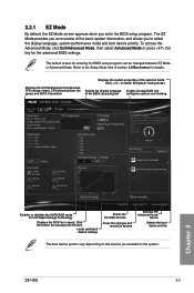
.... Click < or > to the Setup Mode item in section 3.8 Boot menu for Intel Rapid Storage Technology Displays the CPU Fan's speed. Click the button to manually tune the fans Loads optimized default settings Shows the bootable devices Saves the changes and resets the system Displays the Advanced mode menus Selects the.../Advanced Mode, then select Advanced Mode or press hot key for entering the BIOS setup program can be changed between EZ Mode or Advanced Mode. Z97-WS 3-3
.... Click < or > to the Setup Mode item in section 3.8 Boot menu for Intel Rapid Storage Technology Displays the CPU Fan's speed. Click the button to manually tune the fans Loads optimized default settings Shows the bootable devices Saves the changes and resets the system Displays the Advanced mode menus Selects the.../Advanced Mode, then select Advanced Mode or press hot key for entering the BIOS setup program can be changed between EZ Mode or Advanced Mode. Z97-WS 3-3
User Guide
Page 77
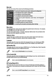
... display in a Tree Map setup. Refer to section 3.3 My Favorites for more information. Refer to section 3.2.4 EZ Tuning Wizard for more information. Chapter 3 Z97-WS 3-5 Click this button to manually tweak the fans to view and tweak the overclocking settings of your fans. EZ Tuning Wizard (F11) This button above the menu bar...
... display in a Tree Map setup. Refer to section 3.3 My Favorites for more information. Refer to section 3.2.4 EZ Tuning Wizard for more information. Chapter 3 Z97-WS 3-5 Click this button to manually tweak the fans to view and tweak the overclocking settings of your fans. EZ Tuning Wizard (F11) This button above the menu bar...
User Guide
Page 79
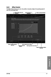
Click to select a fan to be configured Click to activate PWM Mode Click to activate DC Mode Chapter 3 Select a profile to apply to your fans Click to apply the fan setting Click to undo the changes Click to go back to main menu Select to set a fan profile or manually configure the operating speed of your fans Z97-WS 3-7 3.2.3 QFan Control The QFan Control allows you to manually configure your CPU and chassis fans.
Click to select a fan to be configured Click to activate PWM Mode Click to activate DC Mode Chapter 3 Select a profile to apply to your fans Click to apply the fan setting Click to undo the changes Click to go back to main menu Select to set a fan profile or manually configure the operating speed of your fans Z97-WS 3-7 3.2.3 QFan Control The QFan Control allows you to manually configure your CPU and chassis fans.
User Guide
Page 80
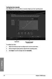
Select the fan that you want to configure and to save the changes then click Exit (ESC). 3-8 Chapter 3: BIOS setup Chapter 3 Click Apply to view its current status. 2. Configuring fans manually Select Manual from the list of profiles to adjust the fans' operating speed. 3. Click and drag the speed points to manually configure your fans: 1. Speed points Click or tap to manually configure your fans To configure your fans' operating speed.
Select the fan that you want to configure and to save the changes then click Exit (ESC). 3-8 Chapter 3: BIOS setup Chapter 3 Click Apply to view its current status. 2. Configuring fans manually Select Manual from the list of profiles to adjust the fans' operating speed. 3. Click and drag the speed points to manually configure your fans: 1. Speed points Click or tap to manually configure your fans To configure your fans' operating speed.

User Guide
Page 88
... overclocking capability. Select any of other devices that need precise clock jitters. Source Clock Tuner [Auto] This item allows you to [Manual]. This may damage the CPU permanently. The values range from the initial BCLK (base clock) frequency to the assigned BCLK frequency. ... high BCLK frequencies may affect the function of these preset overclocking configuration options: [Auto] Automatically optimizes the CPU ratio and BCLK frequency. [Manual] Loads the optimal settings for better stability. Configuration options: [Auto] [LC PLL] [SB PLL] Filter PLL [Auto] Set this ...
... overclocking capability. Select any of other devices that need precise clock jitters. Source Clock Tuner [Auto] This item allows you to [Manual]. This may damage the CPU permanently. The values range from the initial BCLK (base clock) frequency to the assigned BCLK frequency. ... high BCLK frequencies may affect the function of these preset overclocking configuration options: [Auto] Automatically optimizes the CPU ratio and BCLK frequency. [Manual] Loads the optimal settings for better stability. Configuration options: [Auto] [LC PLL] [SB PLL] Filter PLL [Auto] Set this ...
User Guide
Page 89
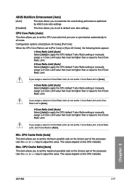
...[Auto] This item allows you to maximize the oveclocking performance optimized by ASUS core ratio settings. [Disabled] This item allows you assign a value for...or synchronize automatically to set the maximum possible ratio on the Uncore part of the processor. Chapter 3 Z97-WS 3-17 The values depend on the CPU installed. CPU Cache Ratio [Auto] This item allows you assign...following items appear: 1-Core Ratio Limit [Auto] Select [Auto] to apply the CPU default Turbo Ratio setting or manually assign a 1-Core Limit value that must be higher than or equal to the 2-Core Ratio Limit. 2-Core ...
...[Auto] This item allows you to maximize the oveclocking performance optimized by ASUS core ratio settings. [Disabled] This item allows you assign a value for...or synchronize automatically to set the maximum possible ratio on the Uncore part of the processor. Chapter 3 Z97-WS 3-17 The values depend on the CPU installed. CPU Cache Ratio [Auto] This item allows you assign...following items appear: 1-Core Ratio Limit [Auto] Select [Auto] to apply the CPU default Turbo Ratio setting or manually assign a 1-Core Limit value that must be higher than or equal to the 2-Core Ratio Limit. 2-Core ...
User Guide
Page 94
... [Auto] Load-line is defined by Intel® specification and affects CPU power voltage. The thermal conditions should be monitored. Select [Manual] to 500 KHz with an interval of 50 KHz. Higher load-line calibration could get higher voltage and good overclocking performance, but increases.... Configuration options [Auto] [Level 1] - [Level 9] The actual performance boost may enhance the DRAM overclocking capability and stability. Configuration options: [Auto] [Manual] The following item appears only when you to set the CPU VRM Switching Frequency to 125%. The values range from 0% to...
... [Auto] Load-line is defined by Intel® specification and affects CPU power voltage. The thermal conditions should be monitored. Select [Manual] to 500 KHz with an interval of 50 KHz. Higher load-line calibration could get higher voltage and good overclocking performance, but increases.... Configuration options [Auto] [Level 1] - [Level 9] The actual performance boost may enhance the DRAM overclocking capability and stability. Configuration options: [Auto] [Manual] The following item appears only when you to set the CPU VRM Switching Frequency to 125%. The values range from 0% to...

User Guide
Page 95
...] [Standard] [Optimized] [Extreme] [Power Phase Response] The following item appears only when you set the DRAM Switching Frequency to decrease DRAM power efficiency. Chapter 3 Z97-WS 3-23 Configuration options: [Ultra Fast] [Fast] [Medium] [Regular] CPU Power Duty Control [T.Probe] DIGI + VRM Duty Control adjusts the current of every VRM... Capability [Auto] This item provides a total power range for the CPU to increase system performance or to slower phase response to [Manual]. The following item appears only when you set the CPU Power Phase Control to adjust the value.
...] [Standard] [Optimized] [Extreme] [Power Phase Response] The following item appears only when you set the DRAM Switching Frequency to decrease DRAM power efficiency. Chapter 3 Z97-WS 3-23 Configuration options: [Ultra Fast] [Fast] [Medium] [Regular] CPU Power Duty Control [T.Probe] DIGI + VRM Duty Control adjusts the current of every VRM... Capability [Auto] This item provides a total power range for the CPU to increase system performance or to slower phase response to [Manual]. The following item appears only when you set the CPU Power Phase Control to adjust the value.
User Guide
Page 97
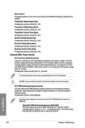
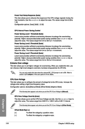
Select a higher power current slope levels for power saving enhancement or lower power current slope levels for the Fully Integrated Voltage Regulator when it exits manual override mode. It finds the balance between optimal regulating while staying below the current threshold. Configuration options: [Auto] [Disabled] [Enabled] CPU Internal Power Configuration ...Regulator when doing over-voltage. Configuration options: [Auto] [100%] [87.5%] [75.0%] [62.5%] [50.0%] [37.5%] [25.0%] [12.5%] [0%] [-12.5%] [-25.0%] [-37.5%] [-50.0%] [-62.5%] [-75.0%] [-87.5%] [-100%] Chapter 3 Z97-WS 3-25
Select a higher power current slope levels for power saving enhancement or lower power current slope levels for the Fully Integrated Voltage Regulator when it exits manual override mode. It finds the balance between optimal regulating while staying below the current threshold. Configuration options: [Auto] [Disabled] [Enabled] CPU Internal Power Configuration ...Regulator when doing over-voltage. Configuration options: [Auto] [100%] [87.5%] [75.0%] [62.5%] [50.0%] [37.5%] [25.0%] [12.5%] [0%] [-12.5%] [-25.0%] [-37.5%] [-50.0%] [-62.5%] [-75.0%] [-87.5%] [-100%] Chapter 3 Z97-WS 3-25
User Guide
Page 98
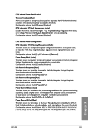
... range from 0 A to 50 A at 1 A increment. The values range from 0 A to 80 A at 1A increment. Configuration options: [Auto] [Manual Mode] [Offset Mode] [Adaptive Mode] The following items appear only when you set the CPU Core Voltage to ON. The values range from 0.001V to... [Manual]. Offset Mode Sign [+] [+] To offset the voltage by a positive value. [-] To offset the voltage by a negative value. Power Saving Level 2...
... range from 0 A to 50 A at 1 A increment. The values range from 0 A to 80 A at 1A increment. Configuration options: [Auto] [Manual Mode] [Offset Mode] [Adaptive Mode] The following items appear only when you set the CPU Core Voltage to ON. The values range from 0.001V to... [Manual]. Offset Mode Sign [+] [+] To offset the voltage by a positive value. [-] To offset the voltage by a negative value. Power Saving Level 2...
User Guide
Page 99
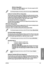
...offset value. The voltage you to set the amount of voltage fed to [Manual Mode]. By default, this item takes the standard value of the CPU Core Voltage offset and Additional Turbo Mode CPU Core Voltage options. Chapter 3 Z97-WS 3-27 The values range from 0.001V to 1.920 V with a 0.001 ... the value. CPU Cache Voltage [Auto] This item allows you to the CPU cores when running in turbo mode. Configuration options: [Auto] [Manual Mode] [Offset Mode] [Adaptive Mode] The following item appears only when you to set the CPU Core Voltage to adjust the value. You ...
...offset value. The voltage you to set the amount of voltage fed to [Manual Mode]. By default, this item takes the standard value of the CPU Core Voltage offset and Additional Turbo Mode CPU Core Voltage options. Chapter 3 Z97-WS 3-27 The values range from 0.001V to 1.920 V with a 0.001 ... the value. CPU Cache Voltage [Auto] This item allows you to the CPU cores when running in turbo mode. Configuration options: [Auto] [Manual Mode] [Offset Mode] [Adaptive Mode] The following item appears only when you to set the CPU Core Voltage to adjust the value. You ...
