User Manual
Page 1
R VX97 Pentium Motherboard USER'S MANUAL
R VX97 Pentium Motherboard USER'S MANUAL

User Manual
Page 4
... Management Setup 42 PNP and PCI Setup 44 Details of the VX97 Motherboard 9 III. FEATURES 8 Features of the VX97 Motherboard 8 Parts of PNP and PCI Setup 44 Load BIOS Defaults 46 4 ASUS VX97 User's Manual Central Processing Unit (CPU 18 4. INSTALLATION 10 Map of the VX97 Motherboard 10 Installation Steps 12 1. System Memory 17 DRAM Memory Installation Procedures...
... Management Setup 42 PNP and PCI Setup 44 Details of the VX97 Motherboard 9 III. FEATURES 8 Features of the VX97 Motherboard 8 Parts of PNP and PCI Setup 44 Load BIOS Defaults 46 4 ASUS VX97 User's Manual Central Processing Unit (CPU 18 4. INSTALLATION 10 Map of the VX97 Motherboard 10 Installation Steps 12 1. System Memory 17 DRAM Memory Installation Procedures...

User Manual
Page 7
... cards Installation of an optional 16-bit Audio card Audio Software Manual (with ASUS I-A16C bundle) Audio Software Manual (with ASUS I-A16C bundle) Item Checklist Please check that your retailer. √ The ASUS VX97 motherboard √ 2 serial port ribbon cables attached to a mounting bracket √ 1 parallel ribbon cable with mounting bracket √ 1 IDE ribbon cable...
... cards Installation of an optional 16-bit Audio card Audio Software Manual (with ASUS I-A16C bundle) Audio Software Manual (with ASUS I-A16C bundle) Item Checklist Please check that your retailer. √ The ASUS VX97 motherboard √ 2 serial port ribbon cables attached to a mounting bracket √ 1 parallel ribbon cable with mounting bracket √ 1 IDE ribbon cable...

User Manual
Page 8
... creating a higher level of compatibility. (Requires DMI-enabled components.) (See section V) • L2 Cache: Comes in a small package. FEATURES Features of the VX97 Motherboard The ASUS VX97 is also supported. • PCI Bus Master IDE Controller: Comes with an onboard PCI Bus Master IDE controller with EPP and ECP capabilities. The Japanese...to form a memory size between 8MB to the Infrared Module for wireless interface and a PS/2 mouse cable set. • Symbios SCSI BIOS: This motherboard has firmware that supports optional ASUS SCSI controller cards. 8 ASUS VX97 User's Manual
... creating a higher level of compatibility. (Requires DMI-enabled components.) (See section V) • L2 Cache: Comes in a small package. FEATURES Features of the VX97 Motherboard The ASUS VX97 is also supported. • PCI Bus Master IDE Controller: Comes with an onboard PCI Bus Master IDE controller with EPP and ECP capabilities. The Japanese...to form a memory size between 8MB to the Infrared Module for wireless interface and a PS/2 mouse cable set. • Symbios SCSI BIOS: This motherboard has firmware that supports optional ASUS SCSI controller cards. 8 ASUS VX97 User's Manual
User Manual
Page 9
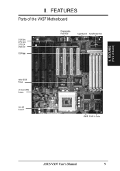
FEATURES (Parts of the VX97 Motherboard 3 ISA Slots 3 PCI Slots 1 PCI/ISA Share Slot IDE/Floppy Programmable Flash ROM Super Multi-I/O Serial/Parallel Ports Intel's 430VX PCIset (4) 72-pin SIMM Sockets CPU ZIF Socket 7 256KB / 512KB L2 Cache ASUS VX97 User's Manual 9 II. FEATURES Parts of Board) II.
FEATURES (Parts of the VX97 Motherboard 3 ISA Slots 3 PCI Slots 1 PCI/ISA Share Slot IDE/Floppy Programmable Flash ROM Super Multi-I/O Serial/Parallel Ports Intel's 430VX PCIset (4) 72-pin SIMM Sockets CPU ZIF Socket 7 256KB / 512KB L2 Cache ASUS VX97 User's Manual 9 II. FEATURES Parts of Board) II.

User Manual
Page 10
... ISA Slot 1 ISA Slot 2 ISA Slot 3 ISA Slot 4 III. INSTALLATION Map of Board) III. Panel Connections 256/512KB OnBoard L2 Cache 10 ASUS VX97 User's Manual INSTALLATION (Map of the VX97 Motherboard Keyboard BIOS Universal Serial Bus (Reserved) PS/2 Mouse Keyboard Flash ROM for BIOS Block Program (Dis/En) Serial Ports COM 1 COM 2 Parallel...
... ISA Slot 1 ISA Slot 2 ISA Slot 3 ISA Slot 4 III. INSTALLATION Map of Board) III. Panel Connections 256/512KB OnBoard L2 Cache 10 ASUS VX97 User's Manual INSTALLATION (Map of the VX97 Motherboard Keyboard BIOS Universal Serial Bus (Reserved) PS/2 Mouse Keyboard Flash ROM for BIOS Block Program (Dis/En) Serial Ports COM 1 COM 2 Parallel...
User Manual
Page 11
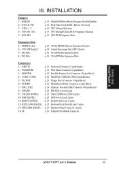
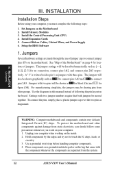
III. INSTALLATION (Map of Board) ASUS VX97 User's Manual 11 INSTALLATION Jumpers 1) BBLKW 2) RTCLR / JP1 3) VID0, 1, 2 4) FS0, FS1, FS2 5) BF0, BF1 p. 13 Flash ROM Boot Block Program (Disable/Enable) p. 13 Real Time ... Block) p. 22 Parallel (Printer) Port Connector (26-pin Block) p. 22 Serial Port COM1 & COM2 (10-pin Blocks) p. 23 Floppy Drive Connector (34-pin Block) p. 23 Motherboard Power Connector (12-pin Block) p. 24 Primary / Secondary IDE Connector (40-pin Blocks) p. 24 IDE LED Activity Light p. 25 Turbo LED/Power LED (2-pins) p. 25...
III. INSTALLATION (Map of Board) ASUS VX97 User's Manual 11 INSTALLATION Jumpers 1) BBLKW 2) RTCLR / JP1 3) VID0, 1, 2 4) FS0, FS1, FS2 5) BF0, BF1 p. 13 Flash ROM Boot Block Program (Disable/Enable) p. 13 Real Time ... Block) p. 22 Parallel (Printer) Port Connector (26-pin Block) p. 22 Serial Port COM1 & COM2 (10-pin Blocks) p. 23 Floppy Drive Connector (34-pin Block) p. 23 Motherboard Power Connector (12-pin Block) p. 24 Primary / Secondary IDE Connector (40-pin Blocks) p. 24 IDE LED Activity Light p. 25 Turbo LED/Power LED (2-pins) p. 25...
User Manual
Page 12
... Motherboard" on the board. INSTALLATION (Jumpers) WARNING: Computer motheboards and components contain very delicate Integrated Circuit (IC) chips. III. See "Map of following steps: 1. The jumpers will also be sharing pins from other components against damage from the system. 12 ASUS VX97 ...be shown as diagramed. Jumpers with the component whenever the components are made through the use of jumpers. To protect the motherboard and other groups. Unplug your computer. 1. INSTALLATION Installation Steps Before using your computer, you work on your computer when ...
... Motherboard" on the board. INSTALLATION (Jumpers) WARNING: Computer motheboards and components contain very delicate Integrated Circuit (IC) chips. III. See "Map of following steps: 1. The jumpers will also be sharing pins from other components against damage from the system. 12 ASUS VX97 ...be shown as diagramed. Jumpers with the component whenever the components are made through the use of jumpers. To protect the motherboard and other groups. Unplug your computer. 1. INSTALLATION Installation Steps Before using your computer, you work on your computer when ...

User Manual
Page 13
... attaching a current meter to your motherboard. Short to allow programming in BIOS SOFTWARE. III. Flash ROM Boot Block Programming (BBLKW) This sets the operation mode of the boot block area of the Programmable Flash ROM to Clear JP1 Operation (Default) RTC RAM Test Mode Battery Test ASUS VX97 User's Manual 13 INSTALLATION (Jumpers...
... attaching a current meter to your motherboard. Short to allow programming in BIOS SOFTWARE. III. Flash ROM Boot Block Programming (BBLKW) This sets the operation mode of the boot block area of the Programmable Flash ROM to Clear JP1 Operation (Default) RTC RAM Test Mode Battery Test ASUS VX97 User's Manual 13 INSTALLATION (Jumpers...
User Manual
Page 14
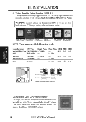
... Planes. Look on this motherboard is supported on the underside of the CPU for the serial number. INSTALLATION (Jumpers) Compatible Cyrix CPU Identification The only Cyrix CPU that is labeled Cyrix 6x86-PR166+ but must be Revision 2.7 or later. The number should read G8DC6620A or later. 14 ASUS VX97 User's Manual III. WARNING...
... Planes. Look on this motherboard is supported on the underside of the CPU for the serial number. INSTALLATION (Jumpers) Compatible Cyrix CPU Identification The only Cyrix CPU that is labeled Cyrix 6x86-PR166+ but must be Revision 2.7 or later. The number should read G8DC6620A or later. 14 ASUS VX97 User's Manual III. WARNING...

User Manual
Page 15
... 66MHz 60MHz [2-3] [1-2] [2-3] [2-3] [1-2] [2-3] [2-3] [2-3] [1-2] [2-3] [1-2] [2-3] [2-3] [2-3] [2-3] *Cyrix 166+ 133MHz 2.0x 66MHz [2-3] [1-2] [2-3] [1-2] [2-3] *NOTE: Only Cyrix Revision 2.7 or later is supported on this motherboard. ASUS VX97 User's Manual 15 The BUS Clock times the BUS Ratio equals the CPU's Internal frequency (the advertised CPU speed). 5. FS0 FS1 FS2 FS0 FS1 FS2... BUS Frequency Ratio (BF0, BF1) These jumpers set together with the Cyrix 166+ installed on this motherboard. These allow the selection of the CPU's External frequency (or BUS Clock).
... 66MHz 60MHz [2-3] [1-2] [2-3] [2-3] [1-2] [2-3] [2-3] [2-3] [1-2] [2-3] [1-2] [2-3] [2-3] [2-3] [2-3] *Cyrix 166+ 133MHz 2.0x 66MHz [2-3] [1-2] [2-3] [1-2] [2-3] *NOTE: Only Cyrix Revision 2.7 or later is supported on this motherboard. ASUS VX97 User's Manual 15 The BUS Clock times the BUS Ratio equals the CPU's Internal frequency (the advertised CPU speed). 5. FS0 FS1 FS2 FS0 FS1 FS2... BUS Frequency Ratio (BF0, BF1) These jumpers set together with the Cyrix 166+ installed on this motherboard. These allow the selection of the CPU's External frequency (or BUS Clock).

User Manual
Page 16
System Memory This motherboard supports four 72-pin SIMMs (Single Inline Memory Modules) of the memory subsystem and will be 128MB or less. Install memory in any or all of the same size memory modules. III. SIMMs must be unstable. INSTALLATION (System Memory) 16 ASUS VX97 User's Manual Modules with more than 24 chips...
System Memory This motherboard supports four 72-pin SIMMs (Single Inline Memory Modules) of the memory subsystem and will be 128MB or less. Install memory in any or all of the same size memory modules. III. SIMMs must be unstable. INSTALLATION (System Memory) 16 ASUS VX97 User's Manual Modules with more than 24 chips...

User Manual
Page 18
... set jumpers for reference only; Insert the CPU with Pentium Processor Lever Lock Blank Installed CPU Example White Dot 18 ASUS VX97 User's Manual Use the notched corner of the CPU with the motherboard should point towards the end the of pin holes and a "1" printed on the fan and close the socket's ...lever. Once completely inserted, hold down on the motherboard next to that came with the white dot as shown. III. The CPU that corner. The picture is a blank area where one orientation as your...
... set jumpers for reference only; Insert the CPU with Pentium Processor Lever Lock Blank Installed CPU Example White Dot 18 ASUS VX97 User's Manual Use the notched corner of the CPU with the motherboard should point towards the end the of pin holes and a "1" printed on the fan and close the socket's ...lever. Once completely inserted, hold down on the motherboard next to that came with the white dot as shown. III. The CPU that corner. The picture is a blank area where one orientation as your...

User Manual
Page 19
...: 1. Secure the card on the slot you removed in step 4. 7. Generally an IRQ must be required to setup your specific card. ASUS VX97 User's Manual 19 First read your expansion card documentation on your computer system's cover. 4. NOTE: PCI Slot 4 has a MediaBus extension ... unplug your expansion card. Remove your expansion card. 3. sible future use . Replace the computer system's cover. 8. Assigning IRQs for your motherboard and expansion cards. III. INSTALLATION (Expansion Cards) III. INSTALLATION 4. Expansion Cards WARNING: Make sure that may cause severe damage to use...
...: 1. Secure the card on the slot you removed in step 4. 7. Generally an IRQ must be required to setup your specific card. ASUS VX97 User's Manual 19 First read your expansion card documentation on your computer system's cover. 4. NOTE: PCI Slot 4 has a MediaBus extension ... unplug your expansion card. Remove your expansion card. 3. sible future use . Replace the computer system's cover. 8. Assigning IRQs for your motherboard and expansion cards. III. INSTALLATION (Expansion Cards) III. INSTALLATION 4. Expansion Cards WARNING: Make sure that may cause severe damage to use...

User Manual
Page 20
... in "My Computer," contains a "System" icon which shows the Interrupt number and address. If the system has both Legacy and PNP may occur. 20 ASUS VX97 User's Manual The PCI and PNP configuration of the BIOS setup utility can be sure that does not work with the Plug and Play (PNP... vendor for ISA Cards Some ISA cards, both Legacy and PNP ISA cards installed, IRQs are then used by Legacy cards. DMA assignments for this motherboard has complied with the BIOS, you wish to see a map of the BIOS Setup utility. III. INSTALLATION (DMA Channels) III. Currently, there are ...
... in "My Computer," contains a "System" icon which shows the Interrupt number and address. If the system has both Legacy and PNP may occur. 20 ASUS VX97 User's Manual The PCI and PNP configuration of the BIOS setup utility can be sure that does not work with the Plug and Play (PNP... vendor for ISA Cards Some ISA cards, both Legacy and PNP ISA cards installed, IRQs are then used by Legacy cards. DMA assignments for this motherboard has complied with the BIOS, you wish to see a map of the BIOS Setup utility. III. INSTALLATION (DMA Channels) III. Currently, there are ...

User Manual
Page 21
...always be known as shown here. 2. Keyboard Connector (5-pin female) This connection is detected. PS/2 Mouse Module Connector ASUS VX97 User's Manual 21 The four corners of the BIOS SOFTWARE section. 1 234 1: GND (Motherboard) 2: DATA 58 3: NC 1 234 (Cable Set) 58 4: VCC 5: CLK 8: NC This optional PS/2 mouse... be connected with the second drive connector no more than 18in. (46cm), with the red stripe on the Pin 1 side of the ASUS Motherboard" on a free expansion slot cover. The system will cause damage to the PS/2 mouse if one is for a standard IBM-compatible...
...always be known as shown here. 2. Keyboard Connector (5-pin female) This connection is detected. PS/2 Mouse Module Connector ASUS VX97 User's Manual 21 The four corners of the BIOS SOFTWARE section. 1 234 1: GND (Motherboard) 2: DATA 58 3: NC 1 234 (Cable Set) 58 4: VCC 5: CLK 8: NC This optional PS/2 mouse... be connected with the second drive connector no more than 18in. (46cm), with the red stripe on the Pin 1 side of the ASUS Motherboard" on a free expansion slot cover. The system will cause damage to the PS/2 mouse if one is for a standard IBM-compatible...

User Manual
Page 23
... when using ribbon cables with pin 5 plugged). Orient the connectors so that the power supply is removed to their receptacles on the connector. ASUS VX97 User's Manual 23 Floppy drive connector (34-pin block ) This connector supports the provided floppy drive ribbon cable. To connect the leads from...GND +5V P8 P9 Power Connector +5V -12V -5V AT Power Connector on the other end to the board, connect the two plugs on Motherboard Power Plugs from the power supply, ensure first that the black wires are black. After connecting the single end to the floppy drives. (Pin...
... when using ribbon cables with pin 5 plugged). Orient the connectors so that the power supply is removed to their receptacles on the connector. ASUS VX97 User's Manual 23 Floppy drive connector (34-pin block ) This connector supports the provided floppy drive ribbon cable. To connect the leads from...GND +5V P8 P9 Power Connector +5V -12V -5V AT Power Connector on the other end to the board, connect the two plugs on Motherboard Power Plugs from the power supply, ensure first that the black wires are black. After connecting the single end to the floppy drives. (Pin...

User Manual
Page 25
INSTALLATION (Connectors) III. Turbo LED Lead (PANEL) The motherboard's turbo function is activated when it detects a short to open moment and therefore leaving it does not have a switch for the connector, you want to ... GND SMI Lead GND Reset SW GND +5V NC Power LED & GND LOCK Keyboard Lock GND +5V GND Speaker GND Connector SPKR System Panel Connectors ASUS VX97 User's Manual 25 See the figure below ) connects to this connector, "Suspend Switch" in order to the case-mounted speaker. Keyboard Lock Switch Lead & System...
INSTALLATION (Connectors) III. Turbo LED Lead (PANEL) The motherboard's turbo function is activated when it detects a short to open moment and therefore leaving it does not have a switch for the connector, you want to ... GND SMI Lead GND Reset SW GND +5V NC Power LED & GND LOCK Keyboard Lock GND +5V GND Speaker GND Connector SPKR System Panel Connectors ASUS VX97 User's Manual 25 See the figure below ) connects to this connector, "Suspend Switch" in order to the case-mounted speaker. Keyboard Lock Switch Lead & System...

User Manual
Page 26
Use the five pins as shown on the Back View and connect a ribbon cable from the module to the motherboard according to a small opening on system cases that support this feature. Infrared Module Connector III. III. NC GND +5V IRRX IRTX Front View...the infrared feature to be available, IRRX you must also configure the setting through "UART2 Use Infrared" in Chipset Features Setup to the motherboard. INSTALLATION (Connectors) 26 ASUS VX97 User's Manual INSTALLATION 14. You must connect an optional Infrared module to select whether UART2 is directed for use with COM2 or IrDA...
Use the five pins as shown on the Back View and connect a ribbon cable from the module to the motherboard according to a small opening on system cases that support this feature. Infrared Module Connector III. III. NC GND +5V IRRX IRTX Front View...the infrared feature to be available, IRRX you must also configure the setting through "UART2 Use Infrared" in Chipset Features Setup to the motherboard. INSTALLATION (Connectors) 26 ASUS VX97 User's Manual INSTALLATION 14. You must connect an optional Infrared module to select whether UART2 is directed for use with COM2 or IrDA...

User Manual
Page 28
... a new BIOS file to the programmable flash ROM chip on the upper left-hand corner of the code displayed on the motherboard. BIOS (Flash Memory Writer) 28 ASUS VX97 User's Manual See "Flash Memory Writer Utility" in case you to File." SST 29EE010 Current BIOS Revision: #401A0-xxxx ...Choose one of the Flash memory chip onto a diskette. Save Current BIOS To File 2. This gives you a backup copy of the original motherboard BIOS in this...
... a new BIOS file to the programmable flash ROM chip on the upper left-hand corner of the code displayed on the motherboard. BIOS (Flash Memory Writer) 28 ASUS VX97 User's Manual See "Flash Memory Writer Utility" in case you to File." SST 29EE010 Current BIOS Revision: #401A0-xxxx ...Choose one of the Flash memory chip onto a diskette. Save Current BIOS To File 2. This gives you a backup copy of the original motherboard BIOS in this...


