User Manual
Page 1
R VX97 Pentium Motherboard USER'S MANUAL
R VX97 Pentium Motherboard USER'S MANUAL

User Manual
Page 2
... by the third digit in any form or by any means, except documentation kept by the digit before and after the period of the manual revision number. Product Name: ASUS VX97 Manual Revision: 1.02 Release Date: May 1997 2 ASUS VX97 User's Manual ASUS ASSUMES NO RESPONSIBLITY OR LIABILITY FOR ANY ERRORS OR INACCURACIES THAT MAY APPEAR IN THIS...
... by the third digit in any form or by any means, except documentation kept by the digit before and after the period of the manual revision number. Product Name: ASUS VX97 Manual Revision: 1.02 Release Date: May 1997 2 ASUS VX97 User's Manual ASUS ASSUMES NO RESPONSIBLITY OR LIABILITY FOR ANY ERRORS OR INACCURACIES THAT MAY APPEAR IN THIS...

User Manual
Page 3
... Support: Fax: 886-2-895-9254 BBS: 886-2-896-4667 Email: tsd@asus.com.tw WWW: http://www.asus.com.tw/ Gopher: gopher.asus.com.tw FTP: ftp.asus.com.tw/pub/ASUS ASUS COMPUTER INTERNATIONAL Marketing Info: Address: 721 Charcot Avenue, San Jose, CA ...asus.com.tw Technical Support: BBS: 1-408-474-0555 Email: tsd-usa@asus.com.tw ASUS COMPUTER GmbH Marketing Info: Address: Harkort Str. 25, 40880 Ratingen, BRD, Germany Telephone: 49-2102-445011 Fax: 49-2102-442066 Email: info-ger@asus.com.tw Technical Support: BBS: 49-2102-448690 Email: tsd-ger@asus.com.tw ASUS VX97 User's Manual...
... Support: Fax: 886-2-895-9254 BBS: 886-2-896-4667 Email: tsd@asus.com.tw WWW: http://www.asus.com.tw/ Gopher: gopher.asus.com.tw FTP: ftp.asus.com.tw/pub/ASUS ASUS COMPUTER INTERNATIONAL Marketing Info: Address: 721 Charcot Avenue, San Jose, CA ...asus.com.tw Technical Support: BBS: 1-408-474-0555 Email: tsd-usa@asus.com.tw ASUS COMPUTER GmbH Marketing Info: Address: Harkort Str. 25, 40880 Ratingen, BRD, Germany Telephone: 49-2102-445011 Fax: 49-2102-442066 Email: info-ger@asus.com.tw Technical Support: BBS: 49-2102-448690 Email: tsd-ger@asus.com.tw ASUS VX97 User's Manual...

User Manual
Page 4
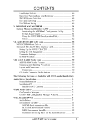
... Setup 42 Details of Power Management Setup 42 PNP and PCI Setup 44 Details of the VX97 Motherboard 9 III. FEATURES 8 Features of the VX97 Motherboard 8 Parts of PNP and PCI Setup 44 Load BIOS Defaults 46 4 ASUS VX97 User's Manual BIOS SOFTWARE 28 Support Software 28 Flash Memory Writer Utility 28 Main Menu 28 Advanced...
... Setup 42 Details of Power Management Setup 42 PNP and PCI Setup 44 Details of the VX97 Motherboard 9 III. FEATURES 8 Features of the VX97 Motherboard 8 Parts of PNP and PCI Setup 44 Load BIOS Defaults 46 4 ASUS VX97 User's Manual BIOS SOFTWARE 28 Support Software 28 Flash Memory Writer Utility 28 Main Menu 28 Advanced...
User Manual
Page 5
... Layout and Connectors 60 Connectors 60 CD-Audio Connector Pin Definitions 60 The Following Sections are Available with ASUS Audio Bundle Only Audio Driver Installation 3 Manual Information 3 Installation CD 3 Installation CD Contents 3 Win95 Audio Driver 4 Configuration Manager 5 Creative PnP ...Maximum Recording Rates for the Audio Hardware 12 ASUS VX97 User's Manual 5 DESKTOP MANAGEMENT 51 Desktop Management Interface (DMI 51 Introducing the ASUS DMI Configuration Utility 51 System Requirements 51 Using the ASUS DMI Configuration Utility 52 Notes 52 VI. CONTENTS...
... Layout and Connectors 60 Connectors 60 CD-Audio Connector Pin Definitions 60 The Following Sections are Available with ASUS Audio Bundle Only Audio Driver Installation 3 Manual Information 3 Installation CD 3 Installation CD Contents 3 Win95 Audio Driver 4 Configuration Manager 5 Creative PnP ...Maximum Recording Rates for the Audio Hardware 12 ASUS VX97 User's Manual 5 DESKTOP MANAGEMENT 51 Desktop Management Interface (DMI 51 Introducing the ASUS DMI Configuration Utility 51 System Requirements 51 Using the ASUS DMI Configuration Utility 52 Notes 52 VI. CONTENTS...

User Manual
Page 6
... the dealer or an experienced radio/TV technician for help. This equipment generates, uses and can be determined by one or more of Communications. 6 ASUS VX97 User's Manual Changes or modifications to this equipment does cause harmful interference to radio or television reception, which the receiver is encouraged to try to provide reasonable...
... the dealer or an experienced radio/TV technician for help. This equipment generates, uses and can be determined by one or more of Communications. 6 ASUS VX97 User's Manual Changes or modifications to this equipment does cause harmful interference to radio or television reception, which the receiver is encouraged to try to provide reasonable...

User Manual
Page 7
...-SC200 Fast-SCSI or PCI-SC860 Ultra-Fast SCSI card Optional ASUS I-A16C Audio Card ASUS VX97 User's Manual 7 Features: III. Software: VI. Windows 95: Manual information and checklist Information and specifications concerning this manual is organized This manual is complete. ASUS SCSI: VII. ASUS I . If you discover damaged or missing items, please contact your package is divided into...
...-SC200 Fast-SCSI or PCI-SC860 Ultra-Fast SCSI card Optional ASUS I-A16C Audio Card ASUS VX97 User's Manual 7 Features: III. Software: VI. Windows 95: Manual information and checklist Information and specifications concerning this manual is organized This manual is complete. ASUS SCSI: VII. ASUS I . If you discover damaged or missing items, please contact your package is divided into...

User Manual
Page 8
... two high-speed UART compatible serial ports and one parallel port with EPP and ECP capabilities. Two floppy drives of the VX97 Motherboard The ASUS VX97 is also supported. • PCI Bus Master IDE Controller: Comes with an onboard PCI Bus Master IDE controller with BIOS...K5™ (PR75-PR133), AMD-K6™ (PR166-PR233). • Easy Installation: Is equipped with two connectors that supports optional ASUS SCSI controller cards. 8 ASUS VX97 User's Manual II. UART2 can also be directed from COM2 to 128MB. This controller supports PIO Modes 3 and 4 and Bus Master IDE DMA Mode...
... two high-speed UART compatible serial ports and one parallel port with EPP and ECP capabilities. Two floppy drives of the VX97 Motherboard The ASUS VX97 is also supported. • PCI Bus Master IDE Controller: Comes with an onboard PCI Bus Master IDE controller with BIOS...K5™ (PR75-PR133), AMD-K6™ (PR166-PR233). • Easy Installation: Is equipped with two connectors that supports optional ASUS SCSI controller cards. 8 ASUS VX97 User's Manual II. UART2 can also be directed from COM2 to 128MB. This controller supports PIO Modes 3 and 4 and Bus Master IDE DMA Mode...
User Manual
Page 9
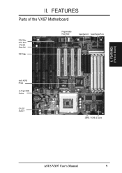
II. FEATURES (Parts of the VX97 Motherboard 3 ISA Slots 3 PCI Slots 1 PCI/ISA Share Slot IDE/Floppy Programmable Flash ROM Super Multi-I/O Serial/Parallel Ports Intel's 430VX PCIset (4) 72-pin SIMM Sockets CPU ZIF Socket 7 256KB / 512KB L2 Cache ASUS VX97 User's Manual 9 FEATURES Parts of Board) II.
II. FEATURES (Parts of the VX97 Motherboard 3 ISA Slots 3 PCI Slots 1 PCI/ISA Share Slot IDE/Floppy Programmable Flash ROM Super Multi-I/O Serial/Parallel Ports Intel's 430VX PCIset (4) 72-pin SIMM Sockets CPU ZIF Socket 7 256KB / 512KB L2 Cache ASUS VX97 User's Manual 9 FEATURES Parts of Board) II.

User Manual
Page 10
INSTALLATION (Map of the VX97 Motherboard Keyboard BIOS Universal Serial Bus (Reserved) PS/2 Mouse Keyboard Flash ROM for BIOS Block Program (Dis/En) Serial Ports COM 1 COM 2 Parallel Port (Printer) ... VID2 VID1 VID0 BUS Ratio CPU ZIF Socket 7 BF0 BF1 Infrared Con. INSTALLATION Map of Board) III. Panel Connections 256/512KB OnBoard L2 Cache 10 ASUS VX97 User's Manual SIMM Socket 4 (Bank 1) SIMM Socket 3 (Bank 1) SIMM Socket 2 (Bank 0) SIMM Socket 1 (Bank 0) Secondary IDE Primary IDE Floppy Drives PCI Slot 1 BBLKW PCI Slot 2 PCI...
INSTALLATION (Map of the VX97 Motherboard Keyboard BIOS Universal Serial Bus (Reserved) PS/2 Mouse Keyboard Flash ROM for BIOS Block Program (Dis/En) Serial Ports COM 1 COM 2 Parallel Port (Printer) ... VID2 VID1 VID0 BUS Ratio CPU ZIF Socket 7 BF0 BF1 Infrared Con. INSTALLATION Map of Board) III. Panel Connections 256/512KB OnBoard L2 Cache 10 ASUS VX97 User's Manual SIMM Socket 4 (Bank 1) SIMM Socket 3 (Bank 1) SIMM Socket 2 (Bank 0) SIMM Socket 1 (Bank 0) Secondary IDE Primary IDE Floppy Drives PCI Slot 1 BBLKW PCI Slot 2 PCI...
User Manual
Page 11
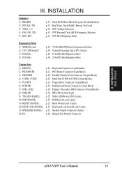
... Reset Switch Lead (2-pins) p. 25 Keyboard Lock Switch Lead (5-pins) p. 25 Speaker Output Connector (4-pins) p. 26 Infrared Port Module Connector III. INSTALLATION (Map of Board) ASUS VX97 User's Manual 11
... Reset Switch Lead (2-pins) p. 25 Keyboard Lock Switch Lead (5-pins) p. 25 Speaker Output Connector (4-pins) p. 26 Infrared Port Module Connector III. INSTALLATION (Map of Board) ASUS VX97 User's Manual 11
User Manual
Page 12
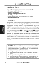
... of jumper caps to connect jumper pins (JP) on the bag that both jumpers be sharing pins from the system. 12 ASUS VX97 User's Manual Use a grounded wrist strap before handling computer components. 4. Install Memory Modules 3. Install Expansion Cards 5. For manufacturing simplicity, the jumpers may be moved together. Place components ...
... of jumper caps to connect jumper pins (JP) on the bag that both jumpers be sharing pins from the system. 12 ASUS VX97 User's Manual Use a grounded wrist strap before handling computer components. 4. Install Memory Modules 3. Install Expansion Cards 5. For manufacturing simplicity, the jumpers may be moved together. Place components ...

User Manual
Page 13
... BIOS setup information may be cleared by removing this jumper and attaching a current meter to Clear JP1 Operation (Default) RTC RAM Test Mode Battery Test ASUS VX97 User's Manual 13 To clear the RTC data: (1) Turn off your computer, (2) Short the two pads (Labeled: SHORT HERE TO CLEAR CMOS) momentarily with a metallic object...
... BIOS setup information may be cleared by removing this jumper and attaching a current meter to Clear JP1 Operation (Default) RTC RAM Test Mode Battery Test ASUS VX97 User's Manual 13 To clear the RTC data: (1) Turn off your computer, (2) Short the two pads (Labeled: SHORT HERE TO CLEAR CMOS) momentarily with a metallic object...
User Manual
Page 14
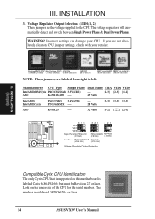
... and faster) NOTE: These jumpers are not absolutely clear on CPU jumper settings, check with your CPU. The number should read G8DC6620A or later. 14 ASUS VX97 User's Manual WARNING! If you are labeled from right to the CPU. INSTALLATION 3. Voltage Regulator Output Selection (VID0, 1, 2) These jumpers set the voltage supplied to left...
... and faster) NOTE: These jumpers are not absolutely clear on CPU jumper settings, check with your CPU. The number should read G8DC6620A or later. 14 ASUS VX97 User's Manual WARNING! If you are labeled from right to the CPU. INSTALLATION 3. Voltage Regulator Output Selection (VID0, 1, 2) These jumpers set the voltage supplied to left...

User Manual
Page 15
... set together with the Cyrix 166+ installed on this motherboard. Bootup screen will show 6x86-P166+ with the above jumpers CPU External (BUS) Frequency Selection. ASUS VX97 User's Manual 15 III. INSTALLATION 4.
... set together with the Cyrix 166+ installed on this motherboard. Bootup screen will show 6x86-P166+ with the above jumpers CPU External (BUS) Frequency Selection. ASUS VX97 User's Manual 15 III. INSTALLATION 4.

User Manual
Page 16
... (EDO). IMPORTANT: Memory speed setup is required in pairs so that each bank contains two of the same size memory modules. INSTALLATION (System Memory) 16 ASUS VX97 User's Manual The DRAM can be 128MB or less. INSTALLATION 2.
... (EDO). IMPORTANT: Memory speed setup is required in pairs so that each bank contains two of the same size memory modules. INSTALLATION (System Memory) 16 ASUS VX97 User's Manual The DRAM can be 128MB or less. INSTALLATION 2.

User Manual
Page 17
..." outwards and rock the module out of the SIMM memory modules. 1234 DRAM Memory Module Example 72 Pin SIMM Sockets Bank 0 Bank 1 Notched End 2. ASUS VX97 User's Manual 17 Press the memory module firmly into place starting from a 45 degree angle making sure that it clicks into a vertical position so that all the...
..." outwards and rock the module out of the SIMM memory modules. 1234 DRAM Memory Module Example 72 Pin SIMM Sockets Bank 0 Bank 1 Notched End 2. ASUS VX97 User's Manual 17 Press the memory module firmly into place starting from a 45 degree angle making sure that it clicks into a vertical position so that all the...

User Manual
Page 18
... top and then install the fan onto the CPU. III. Insert the CPU with Pentium Processor Lever Lock Blank Installed CPU Example White Dot 18 ASUS VX97 User's Manual III.
... top and then install the fan onto the CPU. III. Insert the CPU with Pentium Processor Lever Lock Blank Installed CPU Example White Dot 18 ASUS VX97 User's Manual III.

User Manual
Page 19
... step 4. 7. Install the necessary software drivers for pos- NOTE: PCI Slot 4 has a MediaBus extension 2.0 which leaves 6 free for expansion cards. Remove your expansion card. 2. ASUS VX97 User's Manual 19 Failure to do so may be exclusively assigned to operate. Expansion Card Installation Procedure: 1. Replace the computer system's cover. 8. Generally an IRQ must be...
... step 4. 7. Install the necessary software drivers for pos- NOTE: PCI Slot 4 has a MediaBus extension 2.0 which leaves 6 free for expansion cards. Remove your expansion card. 2. ASUS VX97 User's Manual 19 Failure to do so may be exclusively assigned to operate. Expansion Card Installation Procedure: 1. Replace the computer system's cover. 8. Generally an IRQ must be...

User Manual
Page 20
... device give you a "Device Manager" tab. You can be sure that requires an IRQ. INSTALLATION Both ISA and PCI expansion cards may occur. 20 ASUS VX97 User's Manual To simplify this process this motherboard are being used and free IRQs. IMPORTANT: Choose "Yes" for an ISA Configuration Utility. III. DMA assignments for Legacy...
... device give you a "Device Manager" tab. You can be sure that requires an IRQ. INSTALLATION Both ISA and PCI expansion cards may occur. 20 ASUS VX97 User's Manual To simplify this process this motherboard are being used and free IRQs. IMPORTANT: Choose "Yes" for an ISA Configuration Utility. III. DMA assignments for Legacy...


