User Manual
Page 3
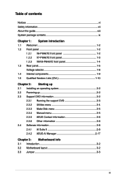
.../V8-P8H67E front panel 1-4 1.3 Rear panel 1-5 Voltage selector 1-8 1.4 Internal components 1-9 1.5 Qualified Vendors Lists (QVL 1-10 Chapter 2: Starting up 2.1 Installing an operating system 2-2 2.2 Powering up 2-2 2.3 Support DVD information 2-2 2.3.1 Running the support DVD 2-3 2.3.2 Utilities menu 2-4 2.3.3 Make Disk menu 2-5 2.3.4 Manual menu 2-5 2.3.5 ASUS Contact information 2-6 2.3.6 Other information 2-6 2.4 Software information 2-8 2.4.1 AI Suite II 2-8 2.4.2 ASUS AI Manager 2-17 Chapter 3: Motherboard info...
.../V8-P8H67E front panel 1-4 1.3 Rear panel 1-5 Voltage selector 1-8 1.4 Internal components 1-9 1.5 Qualified Vendors Lists (QVL 1-10 Chapter 2: Starting up 2.1 Installing an operating system 2-2 2.2 Powering up 2-2 2.3 Support DVD information 2-2 2.3.1 Running the support DVD 2-3 2.3.2 Utilities menu 2-4 2.3.3 Make Disk menu 2-5 2.3.4 Manual menu 2-5 2.3.5 ASUS Contact information 2-6 2.3.6 Other information 2-6 2.4 Software information 2-8 2.4.1 AI Suite II 2-8 2.4.2 ASUS AI Manager 2-17 Chapter 3: Motherboard info...
User Manual
Page 7
Operation safety • Before installing the motherboard and adding devices on it may become wet. • Place the product on a stable surface. • If you are unplugged before using , contact your dealer ... electric shock hazard, disconnect the power cable from the electric outlet before relocating the system. • When adding or removing devices to or from the motherboard, ensure that all power cables are unplugged. • Seek professional assistance before the signal cables are connected. VORSICHT: Explosionsgetahr bei unsachgemäßen Austausch...
Operation safety • Before installing the motherboard and adding devices on it may become wet. • Place the product on a stable surface. • If you are unplugged before using , contact your dealer ... electric shock hazard, disconnect the power cable from the electric outlet before relocating the system. • When adding or removing devices to or from the motherboard, ensure that all power cables are unplugged. • Seek professional assistance before the signal cables are connected. VORSICHT: Explosionsgetahr bei unsachgemäßen Austausch...

User Manual
Page 8
... a general description of the standard package. These documents are not part of the ASUS V-Series P8H67E. Chapter 3: Motherboard info This chapter gives information about the ASUS Vintage V-Series P8H67E barebone system. Where to find more information Refer to complete a task. Conventions used...settings through the BIOS Setup menus and describes the BIOS parameters. This chapter includes the motherboard layout, jumper settings, and connector locations. 4. ASUS Websites The ASUS websites worldwide provide updated information on the front and rear panel, and internal components....
... a general description of the standard package. These documents are not part of the ASUS V-Series P8H67E. Chapter 3: Motherboard info This chapter gives information about the ASUS Vintage V-Series P8H67E barebone system. Where to find more information Refer to complete a task. Conventions used...settings through the BIOS Setup menus and describes the BIOS parameters. This chapter includes the motherboard layout, jumper settings, and connector locations. 4. ASUS Websites The ASUS websites worldwide provide updated information on the front and rear panel, and internal components....

User Manual
Page 12
... computing. 1.2 Front panel The front panel includes the optical drive bays, power button, and several I/O ports. 1.2.1 V6-P8H67E front panel 1 2 3 4 5 6 R 1-2 Chapter 1: System introduction 1.1 Welcome! The system comes in a stylish casing and powered by the ASUS motherboard that supports the Second Generation Intel® Core™ i7 / Core™ i5 / Core™ i3 processors...
... computing. 1.2 Front panel The front panel includes the optical drive bays, power button, and several I/O ports. 1.2.1 V6-P8H67E front panel 1 2 3 4 5 6 R 1-2 Chapter 1: System introduction 1.1 Welcome! The system comes in a stylish casing and powered by the ASUS motherboard that supports the Second Generation Intel® Core™ i7 / Core™ i5 / Core™ i3 processors...
User Manual
Page 19
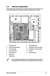
PCI slots 12. DIMM sockets 8. ASUS motherboard 9. PCI Express x16 slot (x16 mode) 10. ASUS V-Series P8H67E 1-9 1.4 Internal components The illustration below is the internal view of the system when you disassemble or assemble the system. Hard disk drive bay 5. Metal bracket ...
PCI slots 12. DIMM sockets 8. ASUS motherboard 9. PCI Express x16 slot (x16 mode) 10. ASUS V-Series P8H67E 1-9 1.4 Internal components The illustration below is the internal view of the system when you disassemble or assemble the system. Hard disk drive bay 5. Metal bracket ...
User Manual
Page 24
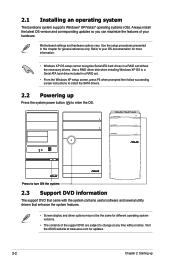
...the features of your OS documentation for different operating system versions. • The contents of the support DVD are subject to change at www.asus.com for general reference only. R Press to your hardware. Refer to turn ON the system 2.3 Support DVD information The support DVD that ... a RAID set . • From the Windows XP setup screen, press F6 when prompted then follow succeeding screen instructions to enter the OS. Motherboard settings and hardware options vary. Use a RAID driver disk when installing Windows XP OS to a Serial ATA hard drive included in this chapter for...
...the features of your OS documentation for different operating system versions. • The contents of the support DVD are subject to change at www.asus.com for general reference only. R Press to your hardware. Refer to turn ON the system 2.3 Support DVD information The support DVD that ... a RAID set . • From the Windows XP setup screen, press F6 when prompted then follow succeeding screen instructions to enter the OS. Motherboard settings and hardware options vary. Use a RAID driver disk when installing Windows XP OS to a Serial ATA hard drive included in this chapter for...
User Manual
Page 25
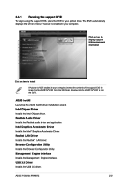
Realtek LAN Driver Installs the Realtek® LAN driver. ASUS V-Series P8H67E 2-3 Intel Graphics Accelerator Driver Installs the Intel® Graphics Accelerator Driver. The DVD.... 2.3.1 Running the support DVD To begin using the support DVD, place the DVD in your computer. ASUS InstAll Launches the ASUS InstAll driver installation wizard. Reaktek Audio Driver Installs the Realtek audio driver and application. Double-click the ASSETUP.... USB 3.0 Driver Installs the USB 3.0 driver. Click an icon to display support DVD/motherboard information Click an item to run the DVD.
Realtek LAN Driver Installs the Realtek® LAN driver. ASUS V-Series P8H67E 2-3 Intel Graphics Accelerator Driver Installs the Intel® Graphics Accelerator Driver. The DVD.... 2.3.1 Running the support DVD To begin using the support DVD, place the DVD in your computer. ASUS InstAll Launches the ASUS InstAll driver installation wizard. Reaktek Audio Driver Installs the Realtek audio driver and application. Double-click the ASSETUP.... USB 3.0 Driver Installs the USB 3.0 driver. Click an icon to display support DVD/motherboard information Click an item to run the DVD.
User Manual
Page 26
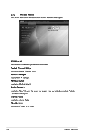
Adobe Reader 9 Installs the Adobe® Reader that the motherboard supports. ASUS InstAll Installs all the utilities through the Installation Wizard. Realtek Ethernet Utility Installs the Realtek Ethernet Utility. ASUS AI Manager Installs ASUS AI Manager. PC-cillin 2010 Installs the PC-cillin 2010 utility. 2-4 Chapter 2: Starting up ASUS AI Suite II Installs the ASUS AI Suite II. 2.3.2 Utilities menu The Utilities menu shows the applications that allows you to open, view, and print documents in Portable Document Format (PDF). Internet Radio Installs the Internet Radio.
Adobe Reader 9 Installs the Adobe® Reader that the motherboard supports. ASUS InstAll Installs all the utilities through the Installation Wizard. Realtek Ethernet Utility Installs the Realtek Ethernet Utility. ASUS AI Manager Installs ASUS AI Manager. PC-cillin 2010 Installs the PC-cillin 2010 utility. 2-4 Chapter 2: Starting up ASUS AI Suite II Installs the ASUS AI Suite II. 2.3.2 Utilities menu The Utilities menu shows the applications that allows you to open, view, and print documents in Portable Document Format (PDF). Internet Radio Installs the Internet Radio.
User Manual
Page 28
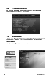
Motherboard Info Displays the general specifications of the support DVD. Click an icon to display the ASUS contact information. You can also find this information on the inside front cover of this user guide. 2.3.6 Other information The icons on the top right corner of the screen give additional information on the motherboard and the contents of the motherboard. 2-6 Chapter 2: Starting up 2.3.5 ASUS Contact information Click the Contact tab to display the specified information.
Motherboard Info Displays the general specifications of the support DVD. Click an icon to display the ASUS contact information. You can also find this information on the inside front cover of this user guide. 2.3.6 Other information The icons on the top right corner of the screen give additional information on the motherboard and the contents of the motherboard. 2-6 Chapter 2: Starting up 2.3.5 ASUS Contact information Click the Contact tab to display the specified information.
User Manual
Page 30
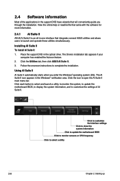
...select a utility 2-8 Chapter 2: Starting up Click to customize the interface settings Click to show the system information Click to update the motherboard BIOS Click to monitor sensors or CPU frequency Click to customize the settings of the applications in the support DVD have wizards that integrates ...an all-in-one interface that will conveniently guide you enter the Windows® operating system (OS). Click the Utilities tab, then click ASUS AI Suite II. 3. Click the icon to launch and operate these utilities simultaneously. Place the support DVD in the Windows® notification...
...select a utility 2-8 Chapter 2: Starting up Click to customize the interface settings Click to show the system information Click to update the motherboard BIOS Click to monitor sensors or CPU frequency Click to customize the settings of the applications in the support DVD have wizards that integrates ...an all-in-one interface that will conveniently guide you enter the Windows® operating system (OS). Click the Utilities tab, then click ASUS AI Suite II. 3. Click the icon to launch and operate these utilities simultaneously. Place the support DVD in the Windows® notification...
User Manual
Page 35
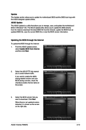
... view the BIOS version information. ASUS V-Series P8H67E 2-13 Select the ASUS FTP site nearest you to download. Click Next. If you want to avoid network traffic. The ASUS Update utility allows you to update the motherboard BIOS and the BIOS boot logo with the ASUS designed update utilities. ASUS Update The ASUS Update is shown as the...
... view the BIOS version information. ASUS V-Series P8H67E 2-13 Select the ASUS FTP site nearest you to download. Click Next. If you want to avoid network traffic. The ASUS Update utility allows you to update the motherboard BIOS and the BIOS boot logo with the ASUS designed update utilities. ASUS Update The ASUS Update is shown as the...

User Manual
Page 37
System Information The System Information section displays the information about the motherboard, CPU, and memory slots. • Click the MB tab to see the details on the motherboard manufacturer, product name, version, and BIOS. • Click the CPU tab to see the details on the processor and the Cache. • Click the SPD tab and then select the memory slot to see the details on the memory module installed on the corresponding slot. ASUS V-Series P8H67E 2-15
System Information The System Information section displays the information about the motherboard, CPU, and memory slots. • Click the MB tab to see the details on the motherboard manufacturer, product name, version, and BIOS. • Click the CPU tab to see the details on the processor and the Cache. • Click the SPD tab and then select the memory slot to see the details on the memory module installed on the corresponding slot. ASUS V-Series P8H67E 2-15

User Manual
Page 43
Information Click the tab on the Support window to go to see the detailed information about your system, motherboard, CPU, BIOS, installed devices, and memory. Support Click any links on the Information window to the ASUS website, technical support website, download support website, or contact information. ASUS V-Series P8H67E 2-21
Information Click the tab on the Support window to go to see the detailed information about your system, motherboard, CPU, BIOS, installed devices, and memory. Support Click any links on the Information window to the ASUS website, technical support website, download support website, or contact information. ASUS V-Series P8H67E 2-21
User Manual
Page 45
This chapter includes the motherboard layout, jumper settings, and connector locations. R Motherboard info Chapter 3 This chapter gives information about the motherboard that comes with the system.
This chapter includes the motherboard layout, jumper settings, and connector locations. R Motherboard info Chapter 3 This chapter gives information about the motherboard that comes with the system.
User Manual
Page 46
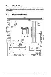
3.1 Introduction The Vintage V-series P8H67E barebone system comes with an ASUS motherboard. DRAM_LED EATXPWR Intel® H67 VIA VT6415 SATA3G_3 BIOS SATA3G_1 SATA3G_2 SB_PWR PANEL SATA6G_1 SATA6G_2 CLRTC PWR_FAN 24.4cm(9.6in) 3-2 Chapter 3: Motherboard info This chapter provides technical information about the motherboard for future upgrades or system reconfiguration. 3.2 Motherboard layout KB_USB34 EPU SPDIFO _HDMI ATX12V ASM...
3.1 Introduction The Vintage V-series P8H67E barebone system comes with an ASUS motherboard. DRAM_LED EATXPWR Intel® H67 VIA VT6415 SATA3G_3 BIOS SATA3G_1 SATA3G_2 SB_PWR PANEL SATA6G_1 SATA6G_2 CLRTC PWR_FAN 24.4cm(9.6in) 3-2 Chapter 3: Motherboard info This chapter provides technical information about the motherboard for future upgrades or system reconfiguration. 3.2 Motherboard layout KB_USB34 EPU SPDIFO _HDMI ATX12V ASM...
User Manual
Page 48
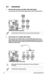
...comply with USB 2.0 specification that supports up to the USB connectors. The USB module is purchased separately. 3-4 Chapter 3: Motherboard info ICH7 Serial ATA connectors (7-pin SATA1, SATA2, SATA3, SATA4) These connectors are for Serial ATA hard disk drives. ... PRO USB2.0 connectors Never connect a 1394 cable to 480 Mbps connection speed. 3.4 Connectors 1. Doing so will damage the motherboard! SATA3G_3 GND RSATA_TXP3 RSATA_TXN3 GND RSATA_RXP3 RSATA_RXN3 GND SATA3G_1 SATA3G_2 GND RSATA_TXP1 RSATA_TXN1 GND RSATA_RXP1 RSATA_RXN1 GND GND RSATA_TXP2 RSATA_TXN2 GND RSATA_RXP2...
...comply with USB 2.0 specification that supports up to the USB connectors. The USB module is purchased separately. 3-4 Chapter 3: Motherboard info ICH7 Serial ATA connectors (7-pin SATA1, SATA2, SATA3, SATA4) These connectors are for Serial ATA hard disk drives. ... PRO USB2.0 connectors Never connect a 1394 cable to 480 Mbps connection speed. 3.4 Connectors 1. Doing so will damage the motherboard! SATA3G_3 GND RSATA_TXP3 RSATA_TXN3 GND RSATA_RXP3 RSATA_RXN3 GND SATA3G_1 SATA3G_2 GND RSATA_TXP1 RSATA_TXN1 GND RSATA_RXP1 RSATA_RXN1 GND GND RSATA_TXP2 RSATA_TXN2 GND RSATA_RXP2...
User Manual
Page 49
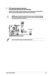
... CPU FAN IN CPU FAN PWM PWR_FAN P8H67-M PRO fan connectors Only the 4-pin CPU fan supports the ASUS Q-Fan2 feature. ASUS V-Series P8H67E 3-5 DO NOT place jumper caps on the motherboard, ensuring that the black wire of each cable matches the ground pin of the connector. Insufficient air flow... inside the system may damage the motherboard components. DO NOT forget to connect the fan cables to the fan ...
... CPU FAN IN CPU FAN PWM PWR_FAN P8H67-M PRO fan connectors Only the 4-pin CPU fan supports the ASUS Q-Fan2 feature. ASUS V-Series P8H67E 3-5 DO NOT place jumper caps on the motherboard, ensuring that the black wire of each cable matches the ground pin of the connector. Insufficient air flow... inside the system may damage the motherboard components. DO NOT forget to connect the fan cables to the fan ...
User Manual
Page 50
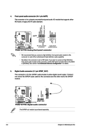
... front panel audio I/O module that you want to connect a High Definition front panel audio module to this connector is purchased separately. 3-6 Chapter 3: Motherboard info Connect one end of the motherboard's high-definition audio capability. • By default, this connector, set to [Enabled]. If you connect a high-definition front panel audio module to...
... front panel audio I/O module that you want to connect a High Definition front panel audio module to this connector is purchased separately. 3-6 Chapter 3: Motherboard info Connect one end of the motherboard's high-definition audio capability. • By default, this connector, set to [Enabled]. If you connect a high-definition front panel audio module to...
User Manual
Page 52
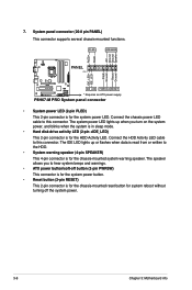
... or flashes when data is read from or written to hear system beeps and warnings. • ATX power button/soft-off the system power. 3-8 Chapter 3: Motherboard info The IDE LED lights up when you to the HDD. • System warning speaker (4-pin SPEAKER) This 4-pin connector is for the chassis-mounted...
... or flashes when data is read from or written to hear system beeps and warnings. • ATX power button/soft-off the system power. 3-8 Chapter 3: Motherboard info The IDE LED lights up when you to the HDD. • System warning speaker (4-pin SPEAKER) This 4-pin connector is for the chassis-mounted...

User Manual
Page 53
... 30 seconds for the system to boot after the whole tuning process, the DRAM_LED lights continuously. Replace the DIMMs with the motherboard may cause system boot failure, and the DRAM_LED near the MemOK! switch does not function under Windows® OS environment. ... system continues memory tuning after using the MemOK! switch to begin automatic memory compatibility tuning for the exact location of failsafe settings. ASUS V-Series P8H67E 3-9 switch until the DRAM_LED starts blinking to boot and load BIOS default settings. function. • The MemOK! function. If...
... 30 seconds for the system to boot after the whole tuning process, the DRAM_LED lights continuously. Replace the DIMMs with the motherboard may cause system boot failure, and the DRAM_LED near the MemOK! switch does not function under Windows® OS environment. ... system continues memory tuning after using the MemOK! switch to begin automatic memory compatibility tuning for the exact location of failsafe settings. ASUS V-Series P8H67E 3-9 switch until the DRAM_LED starts blinking to boot and load BIOS default settings. function. • The MemOK! function. If...


