
786 MANUAL TERMINATOR TUALATIN English V1.0
Page 4
... of the monitor to the graphics card is encouraged to try to correct the interference by the party responsible for a Class B digital device, pursuant to assure compliance with manufacturer's instructions, may not cause harmful interference, and • This device must accept any interference received including interference that interference will not occur in a residential installation. Operation is connected. • Consult...
... of the monitor to the graphics card is encouraged to try to correct the interference by the party responsible for a Class B digital device, pursuant to assure compliance with manufacturer's instructions, may not cause harmful interference, and • This device must accept any interference received including interference that interference will not occur in a residential installation. Operation is connected. • Consult...

786 MANUAL TERMINATOR TUALATIN English V1.0
Page 5
... 1.2 Rear Panel Features 13 Chapter 2: Basic Installation 15 2.1 Remove the Cover 16 2.2 Detach the Drive Frame 17 2.3 Install a CPU 19 2.4 Install System Memory 21 2.5 Install a Hard Disk Drive 22 2.6 Install a CD-ROM Drive 24 2.7 Install a Modem Riser Card 26 2.8 Install a PCI Expansion Card 27 2.9 Re-connect Cables 28 2.10 Replace the Cover 30 2.11 Connect External Devices 32 2.12 Power Supply Specifications 32 Chapter 3: M/B Information 35 3.1 Specifications 36 3.2 Components 38 3.3 Layout 40 3.4 Hardware Setup Procedures 41 3.5 Motherboard Settings 42 3.6 System Memory...
... 1.2 Rear Panel Features 13 Chapter 2: Basic Installation 15 2.1 Remove the Cover 16 2.2 Detach the Drive Frame 17 2.3 Install a CPU 19 2.4 Install System Memory 21 2.5 Install a Hard Disk Drive 22 2.6 Install a CD-ROM Drive 24 2.7 Install a Modem Riser Card 26 2.8 Install a PCI Expansion Card 27 2.9 Re-connect Cables 28 2.10 Replace the Cover 30 2.11 Connect External Devices 32 2.12 Power Supply Specifications 32 Chapter 3: M/B Information 35 3.1 Specifications 36 3.2 Components 38 3.3 Layout 40 3.4 Hardware Setup Procedures 41 3.5 Motherboard Settings 42 3.6 System Memory...
786 MANUAL TERMINATOR TUALATIN English V1.0
Page 10
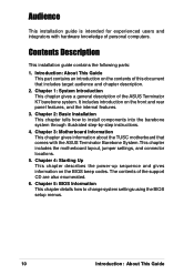
... settings using the BIOS setup menus. 10 Introduction: About This Guide Contents Description This installation guide contains the following parts: 1. Introduction: About This Guide This part contains an introduction on the contents of this document that comes with hardware knowledge of personal computers. Checklist Audience This installation guide is intended for experienced users and integrators with the ASUS Terminator Barebone System.This chapter includes the motherboard layout, jumper settings, and connector locations...
... settings using the BIOS setup menus. 10 Introduction: About This Guide Contents Description This installation guide contains the following parts: 1. Introduction: About This Guide This part contains an introduction on the contents of this document that comes with hardware knowledge of personal computers. Checklist Audience This installation guide is intended for experienced users and integrators with the ASUS Terminator Barebone System.This chapter includes the motherboard layout, jumper settings, and connector locations...

786 MANUAL TERMINATOR TUALATIN English V1.0
Page 13
... shows the rear panel features. Use this switch to select the appropriate voltage according to 115V. 1.2 Rear Panel Features The rear panel of the ASUS Terminator barebone system includes the standard PC99 I/O connectors for external devices, power supply socket, and optional modem connectors. Game/MIDI Connector Serial Port (COM1) PS/2 Mouse Connector PS/2 Keyboard Connector VGA Port Parallel Connector Line Out Connector Line In Connector Microphone Connector LAN Connector (RJ-45) USB Connectors (Ports 0&1) Modem (optional) Power Supply Voltage Selector The switching power supply is...
... shows the rear panel features. Use this switch to select the appropriate voltage according to 115V. 1.2 Rear Panel Features The rear panel of the ASUS Terminator barebone system includes the standard PC99 I/O connectors for external devices, power supply socket, and optional modem connectors. Game/MIDI Connector Serial Port (COM1) PS/2 Mouse Connector PS/2 Keyboard Connector VGA Port Parallel Connector Line Out Connector Line In Connector Microphone Connector LAN Connector (RJ-45) USB Connectors (Ports 0&1) Modem (optional) Power Supply Voltage Selector The switching power supply is...

786 MANUAL TERMINATOR TUALATIN English V1.0
Page 23
2.5 Install a Hard Disk Drive 5. Primary IDE Connector (IDE1) ASUS Terminator Barebone System 23 Red Stripe to the primary IDE connector (blue connector labeled IDE1) on the motherboard. Connect the other end of the HDD. Connect a power cable from the power supply to the power connector at the back of the HDD, matching the red stripe on the IDE Ribbon Cable IDE interface. Connect one end of the IDE hard disk ribbon cable to the IDE interface...
2.5 Install a Hard Disk Drive 5. Primary IDE Connector (IDE1) ASUS Terminator Barebone System 23 Red Stripe to the primary IDE connector (blue connector labeled IDE1) on the motherboard. Connect the other end of the HDD. Connect a power cable from the power supply to the power connector at the back of the HDD, matching the red stripe on the IDE Ribbon Cable IDE interface. Connect one end of the IDE hard disk ribbon cable to the IDE interface...
786 MANUAL TERMINATOR TUALATIN English V1.0
Page 24
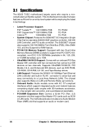
Place the chassis upright. 2. Carefully push the CD-ROM drive into the upper 5.25-inch bay. 3. Insert the CD-ROM drive into the bay until its screw holes align with two screws on the bay as shown. 4. Follow these steps to the instructions in this section if you acquired a model without a CD-ROM. 2.6 Install a CD-ROM Drive A CD-ROM drive is an optional item in this barebone system. Secure the CD-ROM with the holes on each side of the bay. 5.25-inch Drive Bay CD-ROM Screws 24 Chapter 2: Basic Installation Refer to install a CD-ROM drive. 1.
Place the chassis upright. 2. Carefully push the CD-ROM drive into the upper 5.25-inch bay. 3. Insert the CD-ROM drive into the bay until its screw holes align with two screws on the bay as shown. 4. Follow these steps to the instructions in this section if you acquired a model without a CD-ROM. 2.6 Install a CD-ROM Drive A CD-ROM drive is an optional item in this barebone system. Secure the CD-ROM with the holes on each side of the bay. 5.25-inch Drive Bay CD-ROM Screws 24 Chapter 2: Basic Installation Refer to install a CD-ROM drive. 1.
786 MANUAL TERMINATOR TUALATIN English V1.0
Page 36
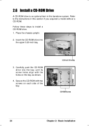
... Memory Support: Equipped with two connectors that support Bus Master PCI cards such as DVD-ROM, CD-ROM, CD-R/RW, LS-120, and Tape Backup drives. • LAN Support: Features the SIS900 10/100Mbps Fast-Ethernet LAN controller and built-in RJ-45 connector to allow fast and easy connectivity to support Intel PC133/PC100- 3.1 Specifications The ASUS TUSC motherboard targets users who require a noncomplicated yet flexible system. The motherboards also includes one Audio...
... Memory Support: Equipped with two connectors that support Bus Master PCI cards such as DVD-ROM, CD-ROM, CD-R/RW, LS-120, and Tape Backup drives. • LAN Support: Features the SIS900 10/100Mbps Fast-Ethernet LAN controller and built-in RJ-45 connector to allow fast and easy connectivity to support Intel PC133/PC100- 3.1 Specifications The ASUS TUSC motherboard targets users who require a noncomplicated yet flexible system. The motherboards also includes one Audio...
786 MANUAL TERMINATOR TUALATIN English V1.0
Page 37
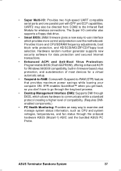
... Multi-I /O controller also supports a floppy disk drive. • Smart BIOS: 2Mbit firmware gives a new easy-to-use interface which allows hardware to communicate within a standard protocol creating a higher level of most devices for wireless connections. The Super I /O: Provides two high-speed UART compatible serial ports and one parallel port with Suspend-to-RAM (STR) feature that provides maximum power savings while leaving your computer ON. STR enables QuickStart™...
... Multi-I /O controller also supports a floppy disk drive. • Smart BIOS: 2Mbit firmware gives a new easy-to-use interface which allows hardware to communicate within a standard protocol creating a higher level of most devices for wireless connections. The Super I /O: Provides two high-speed UART compatible serial ports and one parallel port with Suspend-to-RAM (STR) feature that provides maximum power savings while leaving your computer ON. STR enables QuickStart™...

786 MANUAL TERMINATOR TUALATIN English V1.0
Page 38
.../Celeron Processor ....... 5 Chipsets SiS630ET 3C Integration Single Chip 7 Super I/O Controller 4 2Mbit Programmable Flash EEPROM 3 Main Memory Maximum 1GB support 2 DIMM Sockets 8 PC133 SDRAM support Expansion Slot 2 Riser PCI Slots 14 1 AMR Slot 12 System I/O IOC_MB Connector 1 1 Floppy Disk Drive Connector 6 2 IDE Connectors (UltraDMA66 Support 9 1 Parallel Port Top) 21 1 Serial Port (refer to CGAEX layout on p. 40) 1 VGA Connector Bottom) 22 2 USB Connectors (Port 0 & Port 1) ... (Bottom) 20 1 USB Header (Port 2 & Port 3 17 1 PS/2 Mouse Connector Top) 23 1 PS/2 Keyboard...
.../Celeron Processor ....... 5 Chipsets SiS630ET 3C Integration Single Chip 7 Super I/O Controller 4 2Mbit Programmable Flash EEPROM 3 Main Memory Maximum 1GB support 2 DIMM Sockets 8 PC133 SDRAM support Expansion Slot 2 Riser PCI Slots 14 1 AMR Slot 12 System I/O IOC_MB Connector 1 1 Floppy Disk Drive Connector 6 2 IDE Connectors (UltraDMA66 Support 9 1 Parallel Port Top) 21 1 Serial Port (refer to CGAEX layout on p. 40) 1 VGA Connector Bottom) 22 2 USB Connectors (Port 0 & Port 1) ... (Bottom) 20 1 USB Header (Port 2 & Port 3 17 1 PS/2 Mouse Connector Top) 23 1 PS/2 Keyboard...
786 MANUAL TERMINATOR TUALATIN English V1.0
Page 41
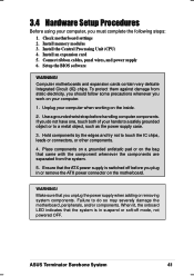
... when working on the inside. 2. Failure to touch the IC chips, leads or connectors, or other components. 4. ASUS Terminator Barebone System 41 Check motherboard settings 2. Install the Central Processing Unit (CPU) 4. Connect ribbon cables, panel wires, and power supply 6. WARNING! Place components on a grounded antistatic pad or on the motherboard. If you unplug the power supply when adding or removing system components. When lit, the onboard LED indicates that the ATX power supply is...
... when working on the inside. 2. Failure to touch the IC chips, leads or connectors, or other components. 4. ASUS Terminator Barebone System 41 Check motherboard settings 2. Install the Central Processing Unit (CPU) 4. Connect ribbon cables, panel wires, and power supply 6. WARNING! Place components on a grounded antistatic pad or on the motherboard. If you unplug the power supply when adding or removing system components. When lit, the onboard LED indicates that the ATX power supply is...

786 MANUAL TERMINATOR TUALATIN English V1.0
Page 49
... connection is detected. Some pins are clearly distinguished from the first connector. 1. See PS/2 Mouse Function Control in the Motherboard Layout. IMPORTANT Ribbon cables should always be less than 15 cm (6 in .), with the red stripe to the power connector on standard AT keyboards. 3.9 Connectors 3.9.1 External Connectors WARNING! PS/2 Keyboard (6-pin female) ASUS Terminator Barebone System 49 Placing jumper caps over these connector pins will cause damage to mini DIN adapter on hard drives and...
... connection is detected. Some pins are clearly distinguished from the first connector. 1. See PS/2 Mouse Function Control in the Motherboard Layout. IMPORTANT Ribbon cables should always be less than 15 cm (6 in .), with the red stripe to the power connector on standard AT keyboards. 3.9 Connectors 3.9.1 External Connectors WARNING! PS/2 Keyboard (6-pin female) ASUS Terminator Barebone System 49 Placing jumper caps over these connector pins will cause damage to mini DIN adapter on hard drives and...
786 MANUAL TERMINATOR TUALATIN English V1.0
Page 53
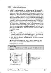
... device. IMPORTANT Use only 40-pin 80-conductor IDE cables for the primary IDE connector and another UltraDMA/ 100/66/33 cable. BIOS supports specific device bootup (see 5.6 Boot Menu). This prevents incorrect orientation when you connect the cables. 2. NOTES: 1. TUSC IDE Connectors PIN 1 ASUS Terminator Barebone System 53 Connect the cable's blue connector to the primary (recommended) or secondary IDE connector, then connect the gray connector to the UltraDMA/100/66/33 slave device (hard disk drive...
... device. IMPORTANT Use only 40-pin 80-conductor IDE cables for the primary IDE connector and another UltraDMA/ 100/66/33 cable. BIOS supports specific device bootup (see 5.6 Boot Menu). This prevents incorrect orientation when you connect the cables. 2. NOTES: 1. TUSC IDE Connectors PIN 1 ASUS Terminator Barebone System 53 Connect the cable's blue connector to the primary (recommended) or secondary IDE connector, then connect the gray connector to the UltraDMA/100/66/33 slave device (hard disk drive...
786 MANUAL TERMINATOR TUALATIN English V1.0
Page 55
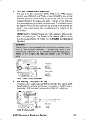
... the case-mounted LED does not light, try reversing the 2-pin plug. IDELED TUSC IDE Activity LED ASUS Terminator Barebone System 55 The red wire should be positive while the black should be monitored using ASUS PC Probe (see 4.2 Install the Operating System). The Rotations Per Minute (RPM) can be ground. IDE Activity LED (2-pin IDELED) This connector supplies power to light up. 4. NOTE: Use the "Rotation" signal only with a specially designed fan...
... the case-mounted LED does not light, try reversing the 2-pin plug. IDELED TUSC IDE Activity LED ASUS Terminator Barebone System 55 The red wire should be positive while the black should be monitored using ASUS PC Probe (see 4.2 Install the Operating System). The Rotations Per Minute (RPM) can be ground. IDE Activity LED (2-pin IDELED) This connector supplies power to light up. 4. NOTE: Use the "Rotation" signal only with a specially designed fan...

786 MANUAL TERMINATOR TUALATIN English V1.0
Page 62
...: a. Award BIOS Beep Codes Beep Meaning One short beep when No error during POST displaying logo Long beeps in some systems, marked with the last device on the front panel of the chassis.) 6. Connect the power cord to switch on the power supply as well as press the ATX power switch on the front of the system case lights up. External SCSI devices (starting with ). 3. For ATX power supplies, the system LED lights up or switch between...
...: a. Award BIOS Beep Codes Beep Meaning One short beep when No error during POST displaying logo Long beeps in some systems, marked with the last device on the front panel of the chassis.) 6. Connect the power cord to switch on the power supply as well as press the ATX power switch on the front of the system case lights up. External SCSI devices (starting with ). 3. For ATX power supplies, the system LED lights up or switch between...
786 MANUAL TERMINATOR TUALATIN English V1.0
Page 65
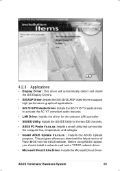
... using ASUS Update, you download the latest version of Flash BIOS from the ASUS website. ASUS Terminator Barebone System 65 This program allows you should install a network card and a TCP/IP network driver. • Microsoft DirectX 8.0a Driver: Installs the Microsoft Direct Driver. 4.2.3 Applications • Display Driver: This driver will automatically detect and install the SiS Display Drivers. • SiS AGP Driver: Installs the SiS 2D/3D AGP video driver to support high-performance graphical applications. • SiS 7018 PCI Audio Driver: Installs...
... using ASUS Update, you download the latest version of Flash BIOS from the ASUS website. ASUS Terminator Barebone System 65 This program allows you should install a network card and a TCP/IP network driver. • Microsoft DirectX 8.0a Driver: Installs the Microsoft Direct Driver. 4.2.3 Applications • Display Driver: This driver will automatically detect and install the SiS Display Drivers. • SiS AGP Driver: Installs the SiS 2D/3D AGP video driver to support high-performance graphical applications. • SiS 7018 PCI Audio Driver: Installs...

786 MANUAL TERMINATOR TUALATIN English V1.0
Page 84
Head This field configures the number of the S.M.A.R.T. (Self-Monitoring, Analysis and Reporting Technology) system which utilizes internal hard disk drive monitoring technology. This feature is automatically configured, the set to [User Type HDD]. Configuration options: [0] [1] [2] [3] [4] [Disabled] 84 Chapter 5: BIOS Information Refer to your drive documentation to determine the correct value to enter into this field, the Type field must be set to [User Type HDD] and the Translation Method field must be set to [Manual]. Configuration options: [Disabled] [2 Sectors] [4 ...
Head This field configures the number of the S.M.A.R.T. (Self-Monitoring, Analysis and Reporting Technology) system which utilizes internal hard disk drive monitoring technology. This feature is automatically configured, the set to [User Type HDD]. Configuration options: [0] [1] [2] [3] [4] [Disabled] 84 Chapter 5: BIOS Information Refer to your drive documentation to determine the correct value to enter into this field, the Type field must be set to [User Type HDD] and the Translation Method field must be set to [Manual]. Configuration options: [Disabled] [2 Sectors] [4 ...
786 MANUAL TERMINATOR TUALATIN English V1.0
Page 87
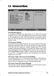
... processor Frequency Multiple is detected locked, you will not be set to [Manual], this must be able to the external frequency of your CPU. Configuration options vary according to access this field. 5.4 Advanced Menu CPU Internal Frequency In JumperFree™Mode, this field allows you to match the internal frequency of your CPU. Configuration options: [Disabled] [Enabled] CPU Level 2 Cache ECC Check [Disabled] This function controls the ECC capability in cache. Configuration options: [Disabled] [Enabled] ASUS Terminator...
... processor Frequency Multiple is detected locked, you will not be set to [Manual], this must be able to the external frequency of your CPU. Configuration options vary according to access this field. 5.4 Advanced Menu CPU Internal Frequency In JumperFree™Mode, this field allows you to match the internal frequency of your CPU. Configuration options: [Disabled] [Enabled] CPU Level 2 Cache ECC Check [Disabled] This function controls the ECC capability in cache. Configuration options: [Disabled] [Enabled] ASUS Terminator...

786 MANUAL TERMINATOR TUALATIN English V1.0
Page 93
... addresses. Configuration options: [1] [3] ASUS Terminator Barebone System 93 Onboard FDC Swap A & B [No Swap] This field allows you to reverse the hardware drive letter assignments of the onboard parallel port connector. Configuration options: [No Swap] [Swap AB] Onboard FDC Smart FIFO [Disabled] Configuration options: [Enabled] [Disabled] Onboard Serial Port 1 [3F8H/IRQ4] Onboard Serial Port 2 [2F8H/IRQ3] These fields allow you to set the operation mode of the parallel port. [Normal] allows normal-speed operation but in...
... addresses. Configuration options: [1] [3] ASUS Terminator Barebone System 93 Onboard FDC Swap A & B [No Swap] This field allows you to reverse the hardware drive letter assignments of the onboard parallel port connector. Configuration options: [No Swap] [Swap AB] Onboard FDC Smart FIFO [Disabled] Configuration options: [Enabled] [Disabled] Onboard Serial Port 1 [3F8H/IRQ4] Onboard Serial Port 2 [2F8H/IRQ3] These fields allow you to set the operation mode of the parallel port. [Normal] allows normal-speed operation but in...

786 MANUAL TERMINATOR TUALATIN English V1.0
Page 98
... set up in the "Control Panel." Configuration options: [Always On] [Suspend > Off] Video Off Method [DPMS OFF] This field defines the video off feature for monitors without power management or "green" features. If the expansion card you need to add the statement, DEVICE=C:\DOS\POWER.EXE, to support the STR function. Configuration options: [Enabled] [Disabled] 98 Chapter 5: BIOS Information IMPORTANT Advanced Power Management (APM) should be installed to activate the video off features. For Windows 3.x and Windows...
... set up in the "Control Panel." Configuration options: [Always On] [Suspend > Off] Video Off Method [DPMS OFF] This field defines the video off feature for monitors without power management or "green" features. If the expansion card you need to add the statement, DEVICE=C:\DOS\POWER.EXE, to support the STR function. Configuration options: [Enabled] [Disabled] 98 Chapter 5: BIOS Information IMPORTANT Advanced Power Management (APM) should be installed to activate the video off features. For Windows 3.x and Windows...

786 MANUAL TERMINATOR TUALATIN English V1.0
Page 103
.... Configuration options: [Disabled] [Enabled] Quick Power On Self Test [Enabled] This field speeds up the Power-On-Self Test (POST) routine by the OS. It can either allow the operation to continue or use a Plug-and-Play (PnP) operating system to clear these data during the Power-On Self Test (POST). When [Yes] is installed or you want to configure the PCI bus slots instead of using the BIOS. Other Boot Device Select [INT18 Device (Network)] Configuration options: [Disabled] [SCSI...
.... Configuration options: [Disabled] [Enabled] Quick Power On Self Test [Enabled] This field speeds up the Power-On-Self Test (POST) routine by the OS. It can either allow the operation to continue or use a Plug-and-Play (PnP) operating system to clear these data during the Power-On Self Test (POST). When [Yes] is installed or you want to configure the PCI bus slots instead of using the BIOS. Other Boot Device Select [INT18 Device (Network)] Configuration options: [Disabled] [SCSI...


