

E732 MANUAL TERMINATOR K7 English V1.0
Page 5
Table of Contents Disclaimer/Copyrights 2 ASUS Contact Information 3 FCC/CDC Statements 4 System Package Contents 7 Introduction: About This Guide 9 Audience 10 Contents Description 10 Chapter 1: System Introduction 11 1.1 Front Panel Features 12 1.2 ... Cover 30 2.11 Connect External Devices 32 2.12 Power Supply Specifications 33 Chapter 3: M/B Information 35 3.1 Specifications 36 3.2 Components 38 3.3 Layout 40 3.4 Hardware Setup Procedures 41 3.5 Motherboard Settings 42 3.6 System Memory 45 3.7 Central Processing Unit (CPU 47 5
Table of Contents Disclaimer/Copyrights 2 ASUS Contact Information 3 FCC/CDC Statements 4 System Package Contents 7 Introduction: About This Guide 9 Audience 10 Contents Description 10 Chapter 1: System Introduction 11 1.1 Front Panel Features 12 1.2 ... Cover 30 2.11 Connect External Devices 32 2.12 Power Supply Specifications 33 Chapter 3: M/B Information 35 3.1 Specifications 36 3.2 Components 38 3.3 Layout 40 3.4 Hardware Setup Procedures 41 3.5 Motherboard Settings 42 3.6 System Memory 45 3.7 Central Processing Unit (CPU 47 5

E732 MANUAL TERMINATOR K7 English V1.0
Page 7
It saves you a lot of time not having to hunt down components when you are assembling the system by yourself, make sure to prepare all the components before starting. System Package Contents The following checklist enumerates the components included in the standard system package. 1) System Chassis 2) Motherboard 3) Switching Power Supply 4) 1.44MB Floppy Disk Drive 5) CD-ROM Drive (optional) 6) 56K PCI Modem Card (optional) 7) Support CD with Drivers and Utilities 8) Installation Guide NOTE If you need them. 7
It saves you a lot of time not having to hunt down components when you are assembling the system by yourself, make sure to prepare all the components before starting. System Package Contents The following checklist enumerates the components included in the standard system package. 1) System Chassis 2) Motherboard 3) Switching Power Supply 4) 1.44MB Floppy Disk Drive 5) CD-ROM Drive (optional) 6) 56K PCI Modem Card (optional) 7) Support CD with Drivers and Utilities 8) Installation Guide NOTE If you need them. 7

E732 MANUAL TERMINATOR K7 English V1.0
Page 10
... This Guide This part contains an introduction on the contents of this document that comes with hardware knowledge of the ASUS Terminator K7 barebone system. Chapter 3: Motherboard Information This chapter gives information about the A7VC motherboard that includes target audience and chapter description. 2. Checklist Audience This installation guide is intended for experienced users and integrators...
... This Guide This part contains an introduction on the contents of this document that comes with hardware knowledge of the ASUS Terminator K7 barebone system. Chapter 3: Motherboard Information This chapter gives information about the A7VC motherboard that includes target audience and chapter description. 2. Checklist Audience This installation guide is intended for experienced users and integrators...

E732 MANUAL TERMINATOR K7 English V1.0
Page 12
... not come installed in the above figure. 12 Chapter 1: System Introduction Push the dotted area of the ASUS A7VC motherboard, a power supply, and a floppy disk drive in the ASUS TriOptix form factor chassis. 1.1 Front Panel Features The ASUS Terminator K7 barebone system is a door that covers accessible I/O features that include two USB connectors (Ports 2&3), a headphone connector...
... not come installed in the above figure. 12 Chapter 1: System Introduction Push the dotted area of the ASUS A7VC motherboard, a power supply, and a floppy disk drive in the ASUS TriOptix form factor chassis. 1.1 Front Panel Features The ASUS Terminator K7 barebone system is a door that covers accessible I/O features that include two USB connectors (Ports 2&3), a headphone connector...

E732 MANUAL TERMINATOR K7 English V1.0
Page 14
Two 5.25" 3.5" HDD 3.5" Floppy Drive Bays Drive Bay Drive Motherboard USB/audio Board Power Supply 14 Chapter 1: System Introduction 1.3 Internal Features The figure below shows the internal view of the system when you can install the other required components to get the system running. You will see here the standard components that come already installed in the system and the places where you remove the cover and flip out the drive frame.
Two 5.25" 3.5" HDD 3.5" Floppy Drive Bays Drive Bay Drive Motherboard USB/audio Board Power Supply 14 Chapter 1: System Introduction 1.3 Internal Features The figure below shows the internal view of the system when you can install the other required components to get the system running. You will see here the standard components that come already installed in the system and the places where you remove the cover and flip out the drive frame.
E732 MANUAL TERMINATOR K7 English V1.0
Page 19
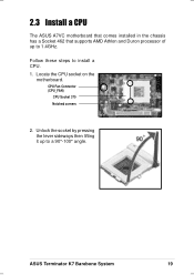
Locate the CPU socket on the motherboard. 2.3 Install a CPU The ASUS A7VC motherboard that comes installed in the chassis has a Socket 462 that supports AMD Athlon and Duron processor of up to a 90°-100° angle. Follow these steps to 1.4GHz. Unlock the socket by pressing the lever sideways then lifting it up to install a CPU. 1. ASUS Terminator K7 Barebone System 19 CPU Fan Connector (CPU_FAN) CPU Socket 370 Notched corners 2.
Locate the CPU socket on the motherboard. 2.3 Install a CPU The ASUS A7VC motherboard that comes installed in the chassis has a Socket 462 that supports AMD Athlon and Duron processor of up to a 90°-100° angle. Follow these steps to 1.4GHz. Unlock the socket by pressing the lever sideways then lifting it up to install a CPU. 1. ASUS Terminator K7 Barebone System 19 CPU Fan Connector (CPU_FAN) CPU Socket 370 Notched corners 2.

E732 MANUAL TERMINATOR K7 English V1.0
Page 20
... If the CPU does not fit completely, check its notched or marked corners match those of the notched corners of the notched corners on the motherboard. Carefully insert the CPU into the socket to the 3-pin CPU_FAN connector on the CPU picture below. 4. Connect the CPU fan cable to prevent bending...
... If the CPU does not fit completely, check its notched or marked corners match those of the notched corners of the notched corners on the motherboard. Carefully insert the CPU into the socket to the 3-pin CPU_FAN connector on the CPU picture below. 4. Connect the CPU fan cable to prevent bending...

E732 MANUAL TERMINATOR K7 English V1.0
Page 21
... until the retaining clips snap back in only one direction. DO NOT force a DIMM into a socket to install a DIMM. 1. Installed DIMM ASUS Terminator K7 Barebone System 21 2.4 Install System Memory The motherboard includes two 168-pin Dual Inline Memory Module (DIMM) sockets. Locate the DIMM sockets on the socket. DIMMs are keyed with notches...
... until the retaining clips snap back in only one direction. DO NOT force a DIMM into a socket to install a DIMM. 1. Installed DIMM ASUS Terminator K7 Barebone System 21 2.4 Install System Memory The motherboard includes two 168-pin Dual Inline Memory Module (DIMM) sockets. Locate the DIMM sockets on the socket. DIMMs are keyed with notches...

E732 MANUAL TERMINATOR K7 English V1.0
Page 23
... at the back of the HDD. Primary IDE Connector (IDE1) ASUS Terminator K7 Barebone System 23 Connect the other end of the HDD, matching the red stripe on the cable with the white connector labeled HDD. 6. Use the cable with Pin 1 on the motherboard. Connect a power cable from the power supply to Pin 1 Power...
... at the back of the HDD. Primary IDE Connector (IDE1) ASUS Terminator K7 Barebone System 23 Connect the other end of the HDD, matching the red stripe on the cable with the white connector labeled HDD. 6. Use the cable with Pin 1 on the motherboard. Connect a power cable from the power supply to Pin 1 Power...

E732 MANUAL TERMINATOR K7 English V1.0
Page 25
... with Pin 1 CD-ROM Audio Cable on the motherboard. Connect the other end of the IDE ribbon cable to the power connector at the back of the CD-ROM. CD-ROM Connector (CD) Secondary IDE Connector (IDE2) ASUS Terminator K7 Barebone System 25 Connect a power cable from the power... supply to the secondary IDE connector (black connector labeled IDE2) on the motherboard. 9. IDE Ribbon Cable 7. Red Stripe to the IDE interface at the back...
... with Pin 1 CD-ROM Audio Cable on the motherboard. Connect the other end of the IDE ribbon cable to the power connector at the back of the CD-ROM. CD-ROM Connector (CD) Secondary IDE Connector (IDE2) ASUS Terminator K7 Barebone System 25 Connect a power cable from the power... supply to the secondary IDE connector (black connector labeled IDE2) on the motherboard. 9. IDE Ribbon Cable 7. Red Stripe to the IDE interface at the back...

E732 MANUAL TERMINATOR K7 English V1.0
Page 26
2.7 Install a Modem Riser Card The motherboard includes an AMR slot that you acquired a model without a modem riser card. Follow these steps to the chassis with a bracket screw. Align the modem card ... bracket cover opposite the AMR expansion slot. 3. Secure the card to install a modem riser card. 1. Connect to a Telephone Line Connect to the instructions in the Terminator barebone system. The figure on the right shows a modem riser card that supports a modem riser card. Refer to a Telephone Set Modem Riser Card Installed on...
2.7 Install a Modem Riser Card The motherboard includes an AMR slot that you acquired a model without a modem riser card. Follow these steps to the chassis with a bracket screw. Align the modem card ... bracket cover opposite the AMR expansion slot. 3. Secure the card to install a modem riser card. 1. Connect to a Telephone Line Connect to the instructions in the Terminator barebone system. The figure on the right shows a modem riser card that supports a modem riser card. Refer to a Telephone Set Modem Riser Card Installed on...

E732 MANUAL TERMINATOR K7 English V1.0
Page 27
... the PCI slot marked PCI1. Press the card firmly until the it is not available. 3. Slot Opening for PCI1 PCI Slot 1 (PCI1) PCI Slot 2 (PCI2) ASUS Terminator K7 Barebone System 27 Secure the card to the chassis with AMR slot). Align the PCI card golden fingers to the slot opening on the PCI... have installed a modem riser card, PCI2 is properly seated on its metal bracket to the PCI slot and its side. 2. 2.8 Install a PCI Expansion Card The motherboard has two 32-bit PCI slots (one shared with a bracket screw.
... the PCI slot marked PCI1. Press the card firmly until the it is not available. 3. Slot Opening for PCI1 PCI Slot 1 (PCI1) PCI Slot 2 (PCI2) ASUS Terminator K7 Barebone System 27 Secure the card to the chassis with AMR slot). Align the PCI card golden fingers to the slot opening on the PCI... have installed a modem riser card, PCI2 is properly seated on its metal bracket to the PCI slot and its side. 2. 2.8 Install a PCI Expansion Card The motherboard has two 32-bit PCI slots (one shared with a bracket screw.

E732 MANUAL TERMINATOR K7 English V1.0
Page 28
.... Connect the power switch and power LED cables to the 2-pin lead marked IDELED. 3. Connect the USB2P cable to the FLOUT/MIC2 connector on the motherboard, matching the red pin stripe with Pin 1. 28 Chapter 2: Basic Installation 2.9 Re-connect Cables You may have disconnected some cables when you replace the ...panel cables with corresponding instructions on where to connect them. Connect the HDD LED cable to their respective leads in the PANEL connector on the motherboard, matching the red pin stripe with Pin 1. 4. Connect the Line Out/Mic cable to the USB1 connector on the...
.... Connect the power switch and power LED cables to the 2-pin lead marked IDELED. 3. Connect the USB2P cable to the FLOUT/MIC2 connector on the motherboard, matching the red pin stripe with Pin 1. 28 Chapter 2: Basic Installation 2.9 Re-connect Cables You may have disconnected some cables when you replace the ...panel cables with corresponding instructions on where to connect them. Connect the HDD LED cable to their respective leads in the PANEL connector on the motherboard, matching the red pin stripe with Pin 1. 4. Connect the Line Out/Mic cable to the USB1 connector on the...

E732 MANUAL TERMINATOR K7 English V1.0
Page 29
...connectors on the Motherboard ASUS Terminator K7 Barebone System 29 You must be connected. FLOUT Lead (for Line Out Cable) MIC2 Lead (for Microphone Cable) Front Panel Connectors USB T: Port0 B: Port1 USB2P UAEX ® LOUT LO2 MIC MIC2 Connect to USB1 Connector on the Motherboard Connect to FLOUT... Lead on the Motherboard Connect to MIC2 Lead on the motherboard and the UAEX Extension Module where the front panel cables must re-connect these cables before replacing ...
...connectors on the Motherboard ASUS Terminator K7 Barebone System 29 You must be connected. FLOUT Lead (for Line Out Cable) MIC2 Lead (for Microphone Cable) Front Panel Connectors USB T: Port0 B: Port1 USB2P UAEX ® LOUT LO2 MIC MIC2 Connect to USB1 Connector on the Motherboard Connect to FLOUT... Lead on the Motherboard Connect to MIC2 Lead on the motherboard and the UAEX Extension Module where the front panel cables must re-connect these cables before replacing ...
E732 MANUAL TERMINATOR K7 English V1.0
Page 35
M/B Information ASUS Terminator K7 Barebone System 35 the heart of the A7VC motherboard - Chapter 3 This chapter gives detailed technical information about the different features of the Terminator K7 Barebone System .
M/B Information ASUS Terminator K7 Barebone System 35 the heart of the A7VC motherboard - Chapter 3 This chapter gives detailed technical information about the different features of the Terminator K7 Barebone System .

E732 MANUAL TERMINATOR K7 English V1.0
Page 36
...3 & 4, and Enhanced IDE devices, such as SCSI or LAN cards. The chipset also supports Wake-on two channels. 3.1 Specifications The ASUS A7VC motherboard targets users who require a noncomplicated yet flexible system. This package also supports PCI LAN, 133/100/66MHz Front Side Bus (FSB), Ultra-... A-based CPUs of up to a Local Area Network (LAN). The motherboards also includes one Audio Modem Riser (AMR) slot that supports an audio or modem card. 36 Chapter 3: Motherboard Information This motherboard includes the basic features sufficient for an entry-level system while employing the...
...3 & 4, and Enhanced IDE devices, such as SCSI or LAN cards. The chipset also supports Wake-on two channels. 3.1 Specifications The ASUS A7VC motherboard targets users who require a noncomplicated yet flexible system. This package also supports PCI LAN, 133/100/66MHz Front Side Bus (FSB), Ultra-... A-based CPUs of up to a Local Area Network (LAN). The motherboards also includes one Audio Modem Riser (AMR) slot that supports an audio or modem card. 36 Chapter 3: Motherboard Information This motherboard includes the basic features sufficient for an entry-level system while employing the...
E732 MANUAL TERMINATOR K7 English V1.0
Page 37
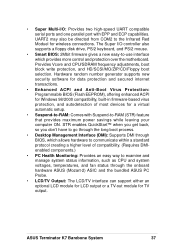
... long boot process. • Desktop Management Interface (DMI): Supports DMI through BIOS, which provides more control and protection over the motherboard. UART2 may also be directed from COM2 to examine and manage system status information, such as CPU and system voltages, temperatures, ...: The LCD/TV interface can support either an optional LCD module for LCD output or a TV-out module for wireless connections. ASUS Terminator K7 Barebone System 37 Hardware random number generator supports new security software for data protection and secured internet transactions. • Enhanced ACPI and...
... long boot process. • Desktop Management Interface (DMI): Supports DMI through BIOS, which provides more control and protection over the motherboard. UART2 may also be directed from COM2 to examine and manage system status information, such as CPU and system voltages, temperatures, ...: The LCD/TV interface can support either an optional LCD module for LCD output or a TV-out module for wireless connections. ASUS Terminator K7 Barebone System 37 Hardware random number generator supports new security software for data protection and secured internet transactions. • Enhanced ACPI and...

E732 MANUAL TERMINATOR K7 English V1.0
Page 38
... (MIC) Connector LO2 Header MIC 2 Header 2 USB Connectors (Port 0 & Port 1) USB2P Header Power ATX Power Supply Connector 5 ATX 12V Connector 2 Form Factor FlexATX 38 Chapter 3: Motherboard Information Location Processor Support Socket 462 for locations.
... (MIC) Connector LO2 Header MIC 2 Header 2 USB Connectors (Port 0 & Port 1) USB2P Header Power ATX Power Supply Connector 5 ATX 12V Connector 2 Form Factor FlexATX 38 Chapter 3: Motherboard Information Location Processor Support Socket 462 for locations.

E732 MANUAL TERMINATOR K7 English V1.0
Page 40
... Modem Riser (AMR) JP1B ADN COM2 USB1 VIA VT8364A Chipset CR2032 3V Lithium Cell CMOS Power LCDTV ® ASUS Mozart VIA 82C686B Chipset WOR CLRTC IDELED IR FLOPPY PANEL 40 Chapter 3: Motherboard Information The motherboard has a side connector for a detachable extension module (CGAEX) that includes a serial port (COM1) and Game/MIDI port. 3.3 Layout...
... Modem Riser (AMR) JP1B ADN COM2 USB1 VIA VT8364A Chipset CR2032 3V Lithium Cell CMOS Power LCDTV ® ASUS Mozart VIA 82C686B Chipset WOR CLRTC IDELED IR FLOPPY PANEL 40 Chapter 3: Motherboard Information The motherboard has a side connector for a detachable extension module (CGAEX) that includes a serial port (COM1) and Game/MIDI port. 3.3 Layout...

E732 MANUAL TERMINATOR K7 English V1.0
Page 41
... a metal object, such as the power supply case. 3. Computer motherboards and expansion cards contain very delicate Integrated Circuit (IC) chips. When lit, the onboard LED indicates that the ATX power supply is in or remove the ATX power connector on the inside. 2. ASUS Terminator K7 Barebone System 41 Failure to do not have one...
... a metal object, such as the power supply case. 3. Computer motherboards and expansion cards contain very delicate Integrated Circuit (IC) chips. When lit, the onboard LED indicates that the ATX power supply is in or remove the ATX power connector on the inside. 2. ASUS Terminator K7 Barebone System 41 Failure to do not have one...


