

Terminator A7VT User Manual
Page 4
...Power supply specifications 40 2.14.1 Input Characteristics 40 2.14.3 Over-Voltage Protection (OVP 40 2.14.2 Output Characteristics 40 Chapter 3: Starting up 3.1 Installing an operating system 42 3.2 Support CD information 42 3.2.1 Running the support CD 42 3.2.2 Utilities menu 43 3.2.3 ASUS Contact information 44 3.2.4 Other information 45 3.3 Software information 47 3.3.1 ASUS PC Probe 47 3.3.2 ASUS... the AwardBIOS Flash Utility 67 5.1.3 Recovering the BIOS with CrashFree BIOS ......... 69 5.1.4 ASUS Update 70 5.2 BIOS Setup program 71 5.2.1 BIOS menu bar 72 5.2.2 Legend bar ...
...Power supply specifications 40 2.14.1 Input Characteristics 40 2.14.3 Over-Voltage Protection (OVP 40 2.14.2 Output Characteristics 40 Chapter 3: Starting up 3.1 Installing an operating system 42 3.2 Support CD information 42 3.2.1 Running the support CD 42 3.2.2 Utilities menu 43 3.2.3 ASUS Contact information 44 3.2.4 Other information 45 3.3 Software information 47 3.3.1 ASUS PC Probe 47 3.3.2 ASUS... the AwardBIOS Flash Utility 67 5.1.3 Recovering the BIOS with CrashFree BIOS ......... 69 5.1.4 ASUS Update 70 5.2 BIOS Setup program 71 5.2.1 BIOS menu bar 72 5.2.2 Legend bar ...

Terminator A7VT User Manual
Page 7
...Operation safety • Before installing devices into the system, carefully read all cables are correctly connected and the power cables are connected. • If the power supply is incorrectly replaced. If you encounter technical problems with the package. • Before using the product, make ...sure all the documentation that the power cables for the devices are unplugged before relocating the system. • When ...
...Operation safety • Before installing devices into the system, carefully read all cables are correctly connected and the power cables are connected. • If the power supply is incorrectly replaced. If you encounter technical problems with the package. • Before using the product, make ...sure all the documentation that the power cables for the devices are unplugged before relocating the system. • When ...

Terminator A7VT User Manual
Page 12
... home entertainment feature. Floppy drive door. This is composed of the ASUS A7VT motherboard, a power supply, and a floppy disk drive in a stylish mini-tower casing, and is powered by the ASUS A7VT motherboard that supports AMD Athlon™ and AMD Duron™ processors. 1.2 Front panel The ASUS Terminator 1 barebone system is an optional IDE optical drive. 2. The system comes...
... home entertainment feature. Floppy drive door. This is composed of the ASUS A7VT motherboard, a power supply, and a floppy disk drive in a stylish mini-tower casing, and is powered by the ASUS A7VT motherboard that supports AMD Athlon™ and AMD Duron™ processors. 1.2 Front panel The ASUS Terminator 1 barebone system is an optional IDE optical drive. 2. The system comes...
Terminator A7VT User Manual
Page 15
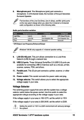
...seriously damage the system! ASUS Terminator 1 A7VT barebone system 15 This Microphone (pink) port connects a microphone. This switch allows you select the 4-channel or 6-channel audio configuration as a mouse, printer, scanner, camera, PDA, and others. 11. Power socket. If the voltage supply in your area is... 200-240V, set the switch to 115V. Voltage selector. Voltage Selector The switching power supply that came with the system has a voltage selector switch below the...
...seriously damage the system! ASUS Terminator 1 A7VT barebone system 15 This Microphone (pink) port connects a microphone. This switch allows you select the 4-channel or 6-channel audio configuration as a mouse, printer, scanner, camera, PDA, and others. 11. Power socket. If the voltage supply in your area is... 200-240V, set the switch to 115V. Voltage selector. Voltage Selector The switching power supply that came with the system has a voltage selector switch below the...

Terminator A7VT User Manual
Page 16
Game/MIDI/COM1 extension module 2. PFC/Non-PFC power supply 7. Motherboard 3. The standard components already installed in the system and the locations of the system when you remove the cover and flip out the drive frame. The system may come with either a PFC (Power Factor Correction) or non-PFC power supply. 3 1 4 5 2 6 7 1. Two 5.25" drive bays (Optional CD-ROM) 4. 3.5" HDD drive bay 5. 3.5" floppy drive 6. USB/audio board 16 Chapter 1: System introduction 1.4 Internal components The figure below shows the internal view of the available drive bays are pointed out.
Game/MIDI/COM1 extension module 2. PFC/Non-PFC power supply 7. Motherboard 3. The standard components already installed in the system and the locations of the system when you remove the cover and flip out the drive frame. The system may come with either a PFC (Power Factor Correction) or non-PFC power supply. 3 1 4 5 2 6 7 1. Two 5.25" drive bays (Optional CD-ROM) 4. 3.5" HDD drive bay 5. 3.5" floppy drive 6. USB/audio board 16 Chapter 1: System introduction 1.4 Internal components The figure below shows the internal view of the available drive bays are pointed out.
Terminator A7VT User Manual
Page 18
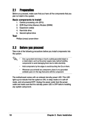
...you install components into the system. • Use a grounded wrist strap or touch a safely grounded object or a metal object, such as the power supply case, before installing any component, place it on them. • Whenever you plan to avoid touching the ICs on a grounded antistatic pad or ...in the bag that came with an onboard standby power LED. Expansion card(s) 4. This LED lights up to install 1. DDR Dual Inline Memory Module (DIMM) 3. Hard disk drive 5. Basic components to...
...you install components into the system. • Use a grounded wrist strap or touch a safely grounded object or a metal object, such as the power supply case, before installing any component, place it on them. • Whenever you plan to avoid touching the ICs on a grounded antistatic pad or ...in the bag that came with an onboard standby power LED. Expansion card(s) 4. This LED lights up to install 1. DDR Dual Inline Memory Module (DIMM) 3. Hard disk drive 5. Basic components to...

Terminator A7VT User Manual
Page 32
... ribbon cable to the secondary IDE connector (black connector labeled SEC_IDE) on the motherboard. 9. CD-ROM audio cable IDE ribbon cable Red stripe to the power connector at the back of the CD-ROM. Connect one end of the CD-ROM audio cable to the 4-pin connector at the back of... on the IDE interface. 7. 5. Use the cable with Pin 1 on the motherboard. Secondary IDE connector (SEC_IDE) CD-ROM connector (CD) 32 Chapter 2: Basic Installation Connect a power cable from the power supply to Pin 1 Power cable (P1) 8.
... ribbon cable to the secondary IDE connector (black connector labeled SEC_IDE) on the motherboard. 9. CD-ROM audio cable IDE ribbon cable Red stripe to the power connector at the back of the CD-ROM. Connect one end of the CD-ROM audio cable to the 4-pin connector at the back of... on the IDE interface. 7. 5. Use the cable with Pin 1 on the motherboard. Secondary IDE connector (SEC_IDE) CD-ROM connector (CD) 32 Chapter 2: Basic Installation Connect a power cable from the power supply to Pin 1 Power cable (P1) 8.

Terminator A7VT User Manual
Page 34
Connect a power cable from the power supply to the power connector at the back of the HDD, matching the red stripe on the cable with the white connector labeled P3. 6. Primary IDE connector (PRI_IDE) 34 Chapter 2: Basic Installation 5. Connect one end of the IDE hard disk ribbon cable to the IDE interface at the back of the IDE ribbon cable to Pin 1 IDE ribbon cable Power cable (P3) 7. Connect the other end of the HDD. Use the cable with Pin 1 on the motherboard. Red stripe to the primary IDE connector (blue connector labeled PRI_IDE1) on the IDE interface.
Connect a power cable from the power supply to the power connector at the back of the HDD, matching the red stripe on the cable with the white connector labeled P3. 6. Primary IDE connector (PRI_IDE) 34 Chapter 2: Basic Installation 5. Connect one end of the IDE hard disk ribbon cable to the IDE interface at the back of the IDE ribbon cable to Pin 1 IDE ribbon cable Power cable (P3) 7. Connect the other end of the HDD. Use the cable with Pin 1 on the motherboard. Red stripe to the primary IDE connector (blue connector labeled PRI_IDE1) on the IDE interface.
Terminator A7VT User Manual
Page 35
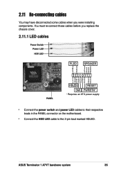
... RESET SMI PWRBTN* * Requires an ATX power supply. • Connect the power switch and power LED cables to their respective leads in the PANEL connector on the motherboard. • Connect the HDD LED cable to the 2-pin lead marked HDLED. You must re-connect these cables before you were installing components. ASUS Terminator 1 A7VT barebone system 35
... RESET SMI PWRBTN* * Requires an ATX power supply. • Connect the power switch and power LED cables to their respective leads in the PANEL connector on the motherboard. • Connect the HDD LED cable to the 2-pin lead marked HDLED. You must re-connect these cables before you were installing components. ASUS Terminator 1 A7VT barebone system 35

Terminator A7VT User Manual
Page 40
at 115Vac, full load cold start at 115Vac 2A max. 2.14 Power supply specifications 2.14.1 Input Characteristics Input Voltage Range Range 1 Range 2 Input Frequency Range Maximum Input ac Current Inrush Current Efficiency Min Nom Max...-5% +5% -5% +5% Ripple Max 50mVp-p 120mVp-p 120mVp-p 50mVp-p 50mVp-p 2.14.3 Over-Voltage Protection (OVP) Output Voltage +5V +12V +3.3V Maximum Voltage 6.5V 15.6V 4.3V The power supply will shut down or automatically recover when the fault condition is removed 40 Chapter 2: Basic Installation at 230Vac, maximum load 90A max. By shorting +5VSB...
at 115Vac, full load cold start at 115Vac 2A max. 2.14 Power supply specifications 2.14.1 Input Characteristics Input Voltage Range Range 1 Range 2 Input Frequency Range Maximum Input ac Current Inrush Current Efficiency Min Nom Max...-5% +5% -5% +5% Ripple Max 50mVp-p 120mVp-p 120mVp-p 50mVp-p 50mVp-p 2.14.3 Over-Voltage Protection (OVP) Output Voltage +5V +12V +3.3V Maximum Voltage 6.5V 15.6V 4.3V The power supply will shut down or automatically recover when the fault condition is removed 40 Chapter 2: Basic Installation at 230Vac, maximum load 90A max. By shorting +5VSB...

Terminator A7VT User Manual
Page 55
... if you can connect to CPU, DRAM in slow refresh, power supply in low power mode) using the connected USB devices. To use the USB device wake-up feature, the total +5VSB power for all devices requiring +5VSB power. The USBPWR34 and USBPWR56 jumpers are for the internal USB connectors...USBPWR56 +5V 3 2 +5VSB (Default) 23 +5VSB (Default) 23 +5VSB (Default) ASUS Terminator T1 A7VT barebone system 55 A7VT ® A7VT USB device wake-up from S1 sleep mode (CPU stopped, DRAM refreshed, system running in reduced power mode). Set to +5VSB to wake up the system from S3, S4, and S5 sleep...
... if you can connect to CPU, DRAM in slow refresh, power supply in low power mode) using the connected USB devices. To use the USB device wake-up feature, the total +5VSB power for all devices requiring +5VSB power. The USBPWR34 and USBPWR56 jumpers are for the internal USB connectors...USBPWR56 +5V 3 2 +5VSB (Default) 23 +5VSB (Default) 23 +5VSB (Default) ASUS Terminator T1 A7VT barebone system 55 A7VT ® A7VT USB device wake-up from S1 sleep mode (CPU stopped, DRAM refreshed, system running in reduced power mode). Set to +5VSB to wake up the system from S3, S4, and S5 sleep...

Terminator A7VT User Manual
Page 60
... fit. ATXPWR +12.0Volts +5V Standby Power Good Ground +5.0 Volts Ground +5.0 Volts Ground +3.3 Volts +3.3 Volts +5.0 Volts +5.0 Volts -5.0 Volts Ground Ground Ground Power Supply On Ground -12.0Volts +3.3Volts A7VT ® ATX12V COM +12V DC A7VT ATX power connectors COM +12V DC Make sure to ...one orientation. MIC_LOUT Head set Left channel Head set Right channel GND A7VT 1 1 ® MIC PWR MIC Signal A7VT Front panel audio connector 60 Chapter 4: Motherboard information The plugs from the power supply are for a chassis-mounted front panel audio I/O module that supports ...
... fit. ATXPWR +12.0Volts +5V Standby Power Good Ground +5.0 Volts Ground +5.0 Volts Ground +3.3 Volts +3.3 Volts +5.0 Volts +5.0 Volts -5.0 Volts Ground Ground Ground Power Supply On Ground -12.0Volts +3.3Volts A7VT ® ATX12V COM +12V DC A7VT ATX power connectors COM +12V DC Make sure to ...one orientation. MIC_LOUT Head set Left channel Head set Right channel GND A7VT 1 1 ® MIC PWR MIC Signal A7VT Front panel audio connector 60 Chapter 4: Motherboard information The plugs from the power supply are for a chassis-mounted front panel audio I/O module that supports ...

Terminator A7VT User Manual
Page 62
...- USBP5+ GND 9. USBP6+ GND NC USB Power USBP4- USB Power USBP6- USBP4+ GND NC A7VT ® A7VT USB connectors USB Power USBP3- PLED SPEAKER +5VSB PLED +5V Ground Ground Speaker +5 V HDLED NC ExtSMI# Ground PWR Ground Reset Ground A7VT ® A7VT System panel connector HDLED RESET SMI PWRBTN* * Requires an ATX power supply. 62 Chapter 4: Motherboard information System panel...
...- USBP5+ GND 9. USBP6+ GND NC USB Power USBP4- USB Power USBP6- USBP4+ GND NC A7VT ® A7VT USB connectors USB Power USBP3- PLED SPEAKER +5VSB PLED +5V Ground Ground Speaker +5 V HDLED NC ExtSMI# Ground PWR Ground Reset Ground A7VT ® A7VT System panel connector HDLED RESET SMI PWRBTN* * Requires an ATX power supply. 62 Chapter 4: Motherboard information System panel...

Terminator A7VT User Manual
Page 86
... set to [Enabled], this parameter allows you to turn on the system. This feature requires an ATX power supply that provides at least 1A on the +5VSB lead. This feature requires an ATX power supply that provides at least 1A on the +5VSB lead. Configuration options: [Hot key] [Password] PS2KB ...Wakeup from S3/S4 Power Up On PCI Devices Modem Ring Resume Power On By RTC Alarm x Date of Month x Resume Time(...
... set to [Enabled], this parameter allows you to turn on the system. This feature requires an ATX power supply that provides at least 1A on the +5VSB lead. This feature requires an ATX power supply that provides at least 1A on the +5VSB lead. Configuration options: [Hot key] [Password] PS2KB ...Wakeup from S3/S4 Power Up On PCI Devices Modem Ring Resume Power On By RTC Alarm x Date of Month x Resume Time(...

Terminator A7VT User Manual
Page 89
... automatically detects and displays the power supply and CPU temperatures in rotations per minute (RPM). Configuration options: [Disabled] [Enabled] Shutdown Temperature [Disabled] When set to [Enabled], the system shuts down when CPU temperature is too high. ASUS Terminator 1 A7VT barebone system 89 5.5.2 Hardware ...monitor This menu shows the hardware monitor configuration settings. Select an item then press to enable or disable the ASUS Q-Fan feature that smartly adjusts the CPU fan...
... automatically detects and displays the power supply and CPU temperatures in rotations per minute (RPM). Configuration options: [Disabled] [Enabled] Shutdown Temperature [Disabled] When set to [Enabled], the system shuts down when CPU temperature is too high. ASUS Terminator 1 A7VT barebone system 89 5.5.2 Hardware ...monitor This menu shows the hardware monitor configuration settings. Select an item then press to enable or disable the ASUS Q-Fan feature that smartly adjusts the CPU fan...


