
TXP4 User Manual
Page 1
R TXP4 Pentium® Motherboard USER'S MANUAL
R TXP4 Pentium® Motherboard USER'S MANUAL

TXP4 User Manual
Page 4
...of BIOS Features Setup 41 Chipset Features Setup 43 Details of the ASUS TXP4 Motherboard 11 III. INSTALLATION 12 ASUS TXP4 Motherboard Layout 12 Installation Steps 14 1. CONTENTS I. FEATURES 8 Features of the ASUS TXP4 Motherboard 8 Introduction to ASUS Smart Series of motherboards 9 Parts of Chipset Features Setup 43 4 ASUS TXP4 User's Manual Central Processing Unit (CPU 22 4. External Connectors 25... 7 II. BIOS SOFTWARE 34 Support Software 34 Flash Memory Writer Utility 34 Main Menu 34 Advanced Features Menu 35 Managing & Updating your Motherboard's BIOS 36 6.
...of BIOS Features Setup 41 Chipset Features Setup 43 Details of the ASUS TXP4 Motherboard 11 III. INSTALLATION 12 ASUS TXP4 Motherboard Layout 12 Installation Steps 14 1. CONTENTS I. FEATURES 8 Features of the ASUS TXP4 Motherboard 8 Introduction to ASUS Smart Series of motherboards 9 Parts of Chipset Features Setup 43 4 ASUS TXP4 User's Manual Central Processing Unit (CPU 22 4. External Connectors 25... 7 II. BIOS SOFTWARE 34 Support Software 34 Flash Memory Writer Utility 34 Main Menu 34 Advanced Features Menu 35 Managing & Updating your Motherboard's BIOS 36 6.

TXP4 User Manual
Page 5
... 64 Software Driver Support 64 Question and Answer 64 ASUS TXP4 User's Manual 5 ASUS PCI SCSI Cards 59 Symbios SCSI BIOS and Drivers 59 ASUS PCI-SC200 & PCI-SC860 SCSI Cards 59 Setting Up the ASUS PCI-SC200 & PCI-SC860 60 Setting the INT Assignment for the ASUS PCI-SC200 60 Terminator Requirements for SCSI Devices... Defaults 50 Load Setup Defaults 50 Supervisor Password and User Password 51 IDE HDD Auto Detection 52 Save & Exit Setup 53 Exit Without Saving 53 ASUS Smart Motherboard Support CD 3.10 55 Desktop Management Interface (DMI 56 Introducing the...
... 64 Software Driver Support 64 Question and Answer 64 ASUS TXP4 User's Manual 5 ASUS PCI SCSI Cards 59 Symbios SCSI BIOS and Drivers 59 ASUS PCI-SC200 & PCI-SC860 SCSI Cards 59 Setting Up the ASUS PCI-SC200 & PCI-SC860 60 Setting the INT Assignment for the ASUS PCI-SC200 60 Terminator Requirements for SCSI Devices... Defaults 50 Load Setup Defaults 50 Supervisor Password and User Password 51 IDE HDD Auto Detection 52 Save & Exit Setup 53 Exit Without Saving 53 ASUS Smart Motherboard Support CD 3.10 55 Desktop Management Interface (DMI 56 Introducing the...

TXP4 User Manual
Page 7
... on -LAN 10/100 Ethernet Card (optional) ASUS TXP4 User's Manual 7 BIOS Software: Instructions on setting up the BIOS software V. Introduction: Manual information and checklist II. Installation: Instructions on setting up the motherboard IV. ASUS SCSI Cards: Installation of the files • ...organized This manual is complete. I . INTRODUCTION How this product III. ASUS L101 Card: Installation of the ASUS LAN card (optional) Item Checklist Please check that your retailer. (1) ASUS Motherboard (1) 9pin male serial + 25pin male serial external connector set (1) 25pin...
... on -LAN 10/100 Ethernet Card (optional) ASUS TXP4 User's Manual 7 BIOS Software: Instructions on setting up the BIOS software V. Introduction: Manual information and checklist II. Installation: Instructions on setting up the motherboard IV. ASUS SCSI Cards: Installation of the files • ...organized This manual is complete. I . INTRODUCTION How this product III. ASUS L101 Card: Installation of the ASUS LAN card (optional) Item Checklist Please check that your retailer. (1) ASUS Motherboard (1) 9pin male serial + 25pin male serial external connector set (1) 25pin...
TXP4 User Manual
Page 8
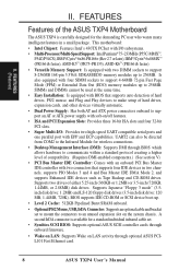
... the ASUS TXP4 Motherboard The ASUS TXP4 is available for the demanding PC user who wants many intelligent features in two channels, supports PIO Modes 3 and 4 and Bus Master IDE DMA Mode 2, and supports Enhanced IDE devices such as Tape Backup and CD-ROM drives. This motherboard: &#...from COM2 to the Infrared Module for wireless connections. • Desktop Management Interface (DMI): Supports DMI through optional ASUS PCIL101 Fast Ethernet card. 8 ASUS TXP4 User's Manual A second IrDA connector is carefully designed for a standard individual infrared cable set to mount the ...
... the ASUS TXP4 Motherboard The ASUS TXP4 is available for the demanding PC user who wants many intelligent features in two channels, supports PIO Modes 3 and 4 and Bus Master IDE DMA Mode 2, and supports Enhanced IDE devices such as Tape Backup and CD-ROM drives. This motherboard: &#...from COM2 to the Infrared Module for wireless connections. • Desktop Management Interface (DMI): Supports DMI through optional ASUS PCIL101 Fast Ethernet card. 8 ASUS TXP4 User's Manual A second IrDA connector is carefully designed for a standard individual infrared cable set to mount the ...

TXP4 User Manual
Page 9
...goals: Support for Plug and Play compatibility and power management for both Windows 95 and Windows NT. ASUS TXP4 User's Manual 9 II. The best of all ASUS 430TX series of motherboards Performance • SDRAM Optimized Performance - ACPI (Advanced Configuration and Power Interface) is no need to... rate using Bus Master UltraDMA/33 IDE which increases the data transfer rate from PCI master busses to memory to 33MB/s. ASUS TX97 series of motherboards meet PC '97 compliancy. Synchronous Dynamic Random Access Memory (SDRAM) which can be used. • PC '97 Compliant...
...goals: Support for Plug and Play compatibility and power management for both Windows 95 and Windows NT. ASUS TXP4 User's Manual 9 II. The best of all ASUS 430TX series of motherboards Performance • SDRAM Optimized Performance - ACPI (Advanced Configuration and Power Interface) is no need to... rate using Bus Master UltraDMA/33 IDE which increases the data transfer rate from PCI master busses to memory to 33MB/s. ASUS TX97 series of motherboards meet PC '97 compliancy. Synchronous Dynamic Random Access Memory (SDRAM) which can be used. • PC '97 Compliant...
TXP4 User Manual
Page 11
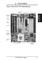
II. FEATURES (Motherboard Parts) II. FEATURES Parts of the ASUS TXP4 Motherboard Super Multi-I/O 3 ISA Slots 4 PCI Slots IDE Connectors AT Power Connector ATX Power Programmable Flash ROM PS/2 Mouse, USB, IrDA Serial, Parallel, Floppy 4 SIMM Sockets 2 DIMM Sockets Intel's 430TX PCIset CPU ZIF Socket 7 "Cool" Switching Voltage Regulators 512KB Pipelined Burst L2 Cache ASUS TXP4 User's Manual 11
II. FEATURES (Motherboard Parts) II. FEATURES Parts of the ASUS TXP4 Motherboard Super Multi-I/O 3 ISA Slots 4 PCI Slots IDE Connectors AT Power Connector ATX Power Programmable Flash ROM PS/2 Mouse, USB, IrDA Serial, Parallel, Floppy 4 SIMM Sockets 2 DIMM Sockets Intel's 430TX PCIset CPU ZIF Socket 7 "Cool" Switching Voltage Regulators 512KB Pipelined Burst L2 Cache ASUS TXP4 User's Manual 11
TXP4 User Manual
Page 12
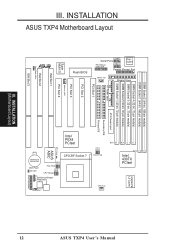
... BIOS Power IDE LED CR2032 3V Lithium Cell Infrared Panel Connectors Chassis Fan 12 III. INSTALLATION ASUS TXP4 Motherboard Layout Floppy Drives Parallel (Printer) Port DIMM Socket 2 (64-bit, 168-pin module) DIMM Socket 1 (64-bit, 168-pin module) SIMM Socket 4 (32-bit, 72-... 512KB PB L2 Cache FS2 FS1 FS0 CPU Fan Clock Freq CPU ZIF Socket 7 Switching Voltage Regulators Freq. Row 0 1 0 1 2 3 2 3 Row 1 0 3 2 Intel 430TX PCIset Keyboard COM 2 ASUS TXP4 User's Manual COM 1 Serial Ports III.
... BIOS Power IDE LED CR2032 3V Lithium Cell Infrared Panel Connectors Chassis Fan 12 III. INSTALLATION ASUS TXP4 Motherboard Layout Floppy Drives Parallel (Printer) Port DIMM Socket 2 (64-bit, 168-pin module) DIMM Socket 1 (64-bit, 168-pin module) SIMM Socket 4 (32-bit, 72-... 512KB PB L2 Cache FS2 FS1 FS0 CPU Fan Clock Freq CPU ZIF Socket 7 Switching Voltage Regulators Freq. Row 0 1 0 1 2 3 2 3 Row 1 0 3 2 Intel 430TX PCIset Keyboard COM 2 ASUS TXP4 User's Manual COM 1 Serial Ports III.
TXP4 User Manual
Page 13
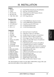
III. INSTALLATION (Map of Board) III. ASUS TXP4 User's Manual 13 INSTALLATION Jumpers 1) BBLKW 2) CLRTC 3) FS0, FS1, FS2 4) BF0, BF1, BF2 5) VID0, VID1, VID2 p. 15 Flash ROM Boot Block Program (Disable/Enable) p. 15 ... Supply, Chassis, CPU Fan Power Leads p. 28 Primary / Secondary IDE Connector (40-1pin Blocks) p. 28 IDE LED Activity Light p. 29 ATX Motherboard Power Connector (20-pin Block) p. 29 AT Motherboard Power Connector (12-pin Block) p. 31 PS/2 Mouse/USB/IR Combo-Connector (18-1pin Block) p. 31 Second Infrared Port Module Connector (5-pin...
III. INSTALLATION (Map of Board) III. ASUS TXP4 User's Manual 13 INSTALLATION Jumpers 1) BBLKW 2) CLRTC 3) FS0, FS1, FS2 4) BF0, BF1, BF2 5) VID0, VID1, VID2 p. 15 Flash ROM Boot Block Program (Disable/Enable) p. 15 ... Supply, Chassis, CPU Fan Power Leads p. 28 Primary / Secondary IDE Connector (40-1pin Blocks) p. 28 IDE LED Activity Light p. 29 ATX Motherboard Power Connector (20-pin Block) p. 29 AT Motherboard Power Connector (12-pin Block) p. 31 PS/2 Mouse/USB/IR Combo-Connector (18-1pin Block) p. 31 Second Infrared Port Module Connector (5-pin...

TXP4 User Manual
Page 14
...motherboards, baseboards and components, such as diagramed. Place components on a grounded antistatic pad or on the bag that both of following steps: 1. Install System Memory Modules 3. Install Expansion Cards 5. For manufacturing simplicity, the jump- To protect them against damage from the system. 14 ASUS TXP4...are separated from static electricity, you should follow some precautions whenever you must complete the following the pin layout on the motherboard. To connect the pins, simply place a plastic jumper cap over the two pins as SCSI cards, contain very ...
...motherboards, baseboards and components, such as diagramed. Place components on a grounded antistatic pad or on the bag that both of following steps: 1. Install System Memory Modules 3. Install Expansion Cards 5. For manufacturing simplicity, the jump- To protect them against damage from the system. 14 ASUS TXP4...are separated from static electricity, you should follow some precautions whenever you must complete the following the pin layout on the motherboard. To connect the pins, simply place a plastic jumper cap over the two pins as SCSI cards, contain very ...

TXP4 User Manual
Page 17
... [2-3] [1-2] [2-3] [1-2] [1-2] [----] 200MHz E-3.0x 66MHz [2-3] [1-2] [2-3] [1-2] [2-3] [----] 166MHz E-2.5x 66MHz [2-3] [1-2] [2-3] [2-3] [2-3] [----] *NOTE: The only IBM or Cyrix 6x86(L) (or M1) that is supported on this motherboard is revision 2.7 or later. (see next page). III. INSTALLATION (Jumpers) ASUS TXP4 User's Manual 17 INSTALLATION Set the jumpers by the Internal speed of the Intel, AMD, IBM, or Cyrix CPU as...
... [2-3] [1-2] [2-3] [1-2] [1-2] [----] 200MHz E-3.0x 66MHz [2-3] [1-2] [2-3] [1-2] [2-3] [----] 166MHz E-2.5x 66MHz [2-3] [1-2] [2-3] [2-3] [2-3] [----] *NOTE: The only IBM or Cyrix 6x86(L) (or M1) that is supported on this motherboard is revision 2.7 or later. (see next page). III. INSTALLATION (Jumpers) ASUS TXP4 User's Manual 17 INSTALLATION Set the jumpers by the Internal speed of the Intel, AMD, IBM, or Cyrix CPU as...

TXP4 User Manual
Page 18
Look on this motherboard must be true for your CPU. Switching regulators ... 2 2 2 2 3 3 3 3 3 2.0Volts 2.1Volts 2.2Volts 2.3Volts 2.4Volts 1 1 1 1 1 2 2 2 2 2 3 3 3 3 3 2.5Volts 2.6Volts 2.7Volts 2.8Volts 2.9Volts 1 1 1 1 2 2 2 2 3 3 3 3 3.0Volts 3.1Volts 3.2Volts 3.3Volts TXP4 CPU Vcore Voltage Selection Dual Plane CPU 1 2 3 3.4V (STD) 1 2 3 3.5V (VRE) Single Plane 18 ASUS TXP4 User's Manual Voltage Regulator Output Selection (VID0, 1, 2) These jumpers set the appropriate VID jumpers according to the CPU. INSTALLATION (Jumpers) Pentium MMX...
Look on this motherboard must be true for your CPU. Switching regulators ... 2 2 2 2 3 3 3 3 3 2.0Volts 2.1Volts 2.2Volts 2.3Volts 2.4Volts 1 1 1 1 1 2 2 2 2 2 3 3 3 3 3 2.5Volts 2.6Volts 2.7Volts 2.8Volts 2.9Volts 1 1 1 1 2 2 2 2 3 3 3 3 3.0Volts 3.1Volts 3.2Volts 3.3Volts TXP4 CPU Vcore Voltage Selection Dual Plane CPU 1 2 3 3.4V (STD) 1 2 3 3.5V (VRE) Single Plane 18 ASUS TXP4 User's Manual Voltage Regulator Output Selection (VID0, 1, 2) These jumpers set the appropriate VID jumpers according to the CPU. INSTALLATION (Jumpers) Pentium MMX...
TXP4 User Manual
Page 19
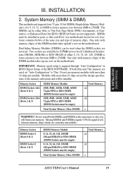
... (EDO) (BEDO & Parity are used . INSTALLATION 2. INSTALLATION (System Memory) III. One side (with memory chips) of the SIMM module takes up one row on the motherboard. Memory Socket SIMM Sockets 1&2 (Rows 0 & 1) SIMM Sockets 3&4 (Rows 2 & 3) SIMM Memory Module 4MB, 8MB, 16MB, 32MB, 64MB 72-pin FPM or EDO...) 4MB, 8MB, 16MB, 32MB, 64MB 72-pin FPM or EDO SIMM (DIMM Sockets must be empty) Total System Memory (Max 256MB) Total Memory x1 x1 = ASUS TXP4 User's Manual 19 Memory Socket DIMM Socket 1 (Rows 0 & 1) DIMM Socket 2 (Rows 2 & 3) DIMM Memory Module 8, 16, 32, 64, 128, 256MB 168-...
... (EDO) (BEDO & Parity are used . INSTALLATION 2. INSTALLATION (System Memory) III. One side (with memory chips) of the SIMM module takes up one row on the motherboard. Memory Socket SIMM Sockets 1&2 (Rows 0 & 1) SIMM Sockets 3&4 (Rows 2 & 3) SIMM Memory Module 4MB, 8MB, 16MB, 32MB, 64MB 72-pin FPM or EDO...) 4MB, 8MB, 16MB, 32MB, 64MB 72-pin FPM or EDO SIMM (DIMM Sockets must be empty) Total System Memory (Max 256MB) Total Memory x1 x1 = ASUS TXP4 User's Manual 19 Memory Socket DIMM Socket 1 (Rows 0 & 1) DIMM Socket 2 (Rows 2 & 3) DIMM Memory Module 8, 16, 32, 64, 128, 256MB 168-...
TXP4 User Manual
Page 21
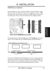
... Pin DIMM Memory Sockets The Dual Inline Memory Module (DIMM) must ask your retailer for this motherboard. You can identify the type of DIMM to be 3.3V Unbuffered for the specifications before purchasing memory modules. ASUS TXP4 User's Manual 21 DIMM Socket 2 DIMM Socket 1 III. INSTALLATION DIMM Memory Installation Insert the module(s) as...
... Pin DIMM Memory Sockets The Dual Inline Memory Module (DIMM) must ask your retailer for this motherboard. You can identify the type of DIMM to be 3.3V Unbuffered for the specifications before purchasing memory modules. ASUS TXP4 User's Manual 21 DIMM Socket 2 DIMM Socket 1 III. INSTALLATION DIMM Memory Installation Insert the module(s) as...
TXP4 User Manual
Page 22
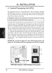
INSTALLATION 3. WARNING! Insert the CPU with Pentium Processor 22 ASUS TXP4 User's Manual The white dot should point towards the end the of the CPU. you should have a CPU fan that you turn off your system. R Lever Lock Blank Notch TXP4 ZIF Socket 7 with the correct orientation as shown. INSTALLATION ... 5 processors. Because the CPU has a corner pin for reference only; With the added weight of pin holes and a "1" printed on the motherboard next to a 90-degree right angle. Without a fan circulating air on the CPU that will only fit in the one hole is missing from...
INSTALLATION 3. WARNING! Insert the CPU with Pentium Processor 22 ASUS TXP4 User's Manual The white dot should point towards the end the of the CPU. you should have a CPU fan that you turn off your system. R Lever Lock Blank Notch TXP4 ZIF Socket 7 with the correct orientation as shown. INSTALLATION ... 5 processors. Because the CPU has a corner pin for reference only; With the added weight of pin holes and a "1" printed on the motherboard next to a 90-degree right angle. Without a fan circulating air on the CPU that will only fit in the one hole is missing from...

TXP4 User Manual
Page 23
...expansion cards may cause severe damage to setup your expansion card documentation on any hardware and software settings that you unplug your motherboard and expansion cards. First read your specific card. Install the necessary software drivers for expansion cards. System IRQs are two ... cover. 4. In an standard design there are 16 IRQs available but most of them are then used by parts of ISA cards. ASUS TXP4 User's Manual 23 Expansion Card Installation Procedure: 1. Keep the bracket for Expansion Cards Some expansion cards need to operate. INSTALLATION 4. Remove...
...expansion cards may cause severe damage to setup your expansion card documentation on any hardware and software settings that you unplug your motherboard and expansion cards. First read your specific card. Install the necessary software drivers for expansion cards. System IRQs are two ... cover. 4. In an standard design there are 16 IRQs available but most of them are then used by parts of ISA cards. ASUS TXP4 User's Manual 23 Expansion Card Installation Procedure: 1. Keep the bracket for Expansion Cards Some expansion cards need to operate. INSTALLATION 4. Remove...

TXP4 User Manual
Page 24
...Cards and Hardware Monitor The onboard hardware monitor uses the address 290H-297H so legacy ISA cards must not use this motherboard are being used by Legacy cards. INSTALLATION The original ISA expansion card design, now referred to reserve). For PNP...clicking on the ISA bus. Make sure that the jumpers on this motherboard has complied with the BIOS, you a "Device Manager" tab. To simplify this process this motherboard use the same IRQs or your PCI cards are in the PCI and... to the system. Since all the PCI slots on your computer will occur. 24 ASUS TXP4 User's Manual
...Cards and Hardware Monitor The onboard hardware monitor uses the address 290H-297H so legacy ISA cards must not use this motherboard are being used by Legacy cards. INSTALLATION The original ISA expansion card design, now referred to reserve). For PNP...clicking on the ISA bus. Make sure that the jumpers on this motherboard has complied with the BIOS, you a "Device Manager" tab. To simplify this process this motherboard use the same IRQs or your PCI cards are in the PCI and... to the system. Since all the PCI slots on your computer will occur. 24 ASUS TXP4 User's Manual

TXP4 User Manual
Page 25
... must be connected with the red stripe on the other end to the floppy drives. (Pin 5 is removed to prevent inserting in "Map of the ASUS Motherboard." After connecting the single end to Pin 1 NOTE: Most 3.5inch floppy drive's Pin 1 is the side closest to the floppy drive. R Pin 1 Connect the Red.../102-key, or 104key keyboard (Windows 95-compatible). III. Some pins are used for connectors or power sources. Pin 1 is away from the first connector. 1. TXP4 Keyboard Connector 2. If your motherboard. TXP4 Floppy Drive Connector ASUS TXP4 User's Manual 25
... must be connected with the red stripe on the other end to the floppy drives. (Pin 5 is removed to prevent inserting in "Map of the ASUS Motherboard." After connecting the single end to Pin 1 NOTE: Most 3.5inch floppy drive's Pin 1 is the side closest to the floppy drive. R Pin 1 Connect the Red.../102-key, or 104key keyboard (Windows 95-compatible). III. Some pins are used for connectors or power sources. Pin 1 is away from the first connector. 1. TXP4 Keyboard Connector 2. If your motherboard. TXP4 Floppy Drive Connector ASUS TXP4 User's Manual 25

TXP4 User Manual
Page 27
INSTALLATION 5. WARNING! INSTALLATION (Connectors) ASUS TXP4 User's Manual 27 III. Depending on the fan manufacturer, the wiring and plug may occur to the motherboard and/or the CPU fan if these pins are not jumpers, do not place jumper caps over these pins. These are incorrectly used. The red ... Cooling Fan Connectors (FAN, 3 pins) This connector supports a 3-pin CPU cooling fan of 500mAMP (6WATT) or less with a minimum of 3,500RPM. The CPU and/or motherboard will overheat if there is no airflow across the CPU. Power Supply Fan R Chassis Fan Power CPU Fan Power...
INSTALLATION 5. WARNING! INSTALLATION (Connectors) ASUS TXP4 User's Manual 27 III. Depending on the fan manufacturer, the wiring and plug may occur to the motherboard and/or the CPU fan if these pins are not jumpers, do not place jumper caps over these pins. These are incorrectly used. The red ... Cooling Fan Connectors (FAN, 3 pins) This connector supports a 3-pin CPU cooling fan of 500mAMP (6WATT) or less with a minimum of 3,500RPM. The CPU and/or motherboard will overheat if there is no airflow across the CPU. Power Supply Fan R Chassis Fan Power CPU Fan Power...

TXP4 User Manual
Page 29
... supplies provide two plugs (P8 and P9), each containing six wires, two of the different hole sizes. R TXP4 AT Power Connector +5V -5V GND +12V PG -12V +5V Power Connector on Motherboard RED RED RED P9 WHT BLK BLK BLK BLK BLU YLW P8 RED ORG Power Plugs from Power Supply... Using a slight angle, align the plastic guide pins on the lead to their receptacles on your system if your ATX power supply must supply at least 720mAmp. ASUS TXP4 User's Manual...
... supplies provide two plugs (P8 and P9), each containing six wires, two of the different hole sizes. R TXP4 AT Power Connector +5V -5V GND +12V PG -12V +5V Power Connector on Motherboard RED RED RED P9 WHT BLK BLK BLK BLK BLU YLW P8 RED ORG Power Plugs from Power Supply... Using a slight angle, align the plastic guide pins on the lead to their receptacles on your system if your ATX power supply must supply at least 720mAmp. ASUS TXP4 User's Manual...


