User Manual
Page 2
...Acrobat are released for identification or explanation and to the owners' benefit, without the express written permission of ASUSTeK COMPUTER INC. ("ASUS"). All Rights Reserved. USER'S NOTICE No part of this manual may or may be registered trademarks or copyrights of their respective ... stored in a retrieval system, or translated into any language in the manual revision number. Product Name: ASUS TXP4-X Manual Revision: 1.01 Release Date: July 1997 2 ASUS TXP4-X User's Manual ASUS PROVIDES THIS MANUAL "AS IS" WITHOUT WARRANTY OF ANY KIND, EITHER EXPRESS OR IMPLIED, INCLUDING BUT NOT...
...Acrobat are released for identification or explanation and to the owners' benefit, without the express written permission of ASUSTeK COMPUTER INC. ("ASUS"). All Rights Reserved. USER'S NOTICE No part of this manual may or may be registered trademarks or copyrights of their respective ... stored in a retrieval system, or translated into any language in the manual revision number. Product Name: ASUS TXP4-X Manual Revision: 1.01 Release Date: July 1997 2 ASUS TXP4-X User's Manual ASUS PROVIDES THIS MANUAL "AS IS" WITHOUT WARRANTY OF ANY KIND, EITHER EXPRESS OR IMPLIED, INCLUDING BUT NOT...
User Manual
Page 3
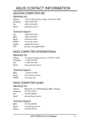
....tw Technical Support Fax: +886-2-895-9254 BBS: +886-2-896-4667 Email: tsd@asus.com.tw WWW: www.asus.com.tw Gopher: gopher.asus.com.tw FTP: ftp.asus.com.tw/pub/ASUS ASUS COMPUTER INTERNATIONAL Marketing Info Address: Telephone: Fax: Email: 721 Charcot Avenue, San Jose, CA ...asus.com.tw WWW: www.asus.com ASUS COMPUTER GmbH Marketing Info Address: Harkort Str. 25, 40880 Ratingen, BRD, Germany Telephone: 49-2102-445011 Fax: 49-2102-442066 Email: info-ger@asus.com.tw Technical Support BBS: 49-2102-448690 Email: tsd-ger@asus.com.tw Hotline: 49-2102-499712 ASUS TXP4...
....tw Technical Support Fax: +886-2-895-9254 BBS: +886-2-896-4667 Email: tsd@asus.com.tw WWW: www.asus.com.tw Gopher: gopher.asus.com.tw FTP: ftp.asus.com.tw/pub/ASUS ASUS COMPUTER INTERNATIONAL Marketing Info Address: Telephone: Fax: Email: 721 Charcot Avenue, San Jose, CA ...asus.com.tw WWW: www.asus.com ASUS COMPUTER GmbH Marketing Info Address: Harkort Str. 25, 40880 Ratingen, BRD, Germany Telephone: 49-2102-445011 Fax: 49-2102-442066 Email: info-ger@asus.com.tw Technical Support BBS: 49-2102-448690 Email: tsd-ger@asus.com.tw Hotline: 49-2102-499712 ASUS TXP4...
User Manual
Page 4
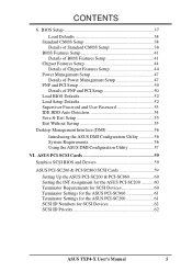
CONTENTS I. FEATURES 8 Features of the ASUS TXP4-X Motherboard 8 Introduction to ASUS TX97 Series of Motherboards 9 The ASUS TXP4-X Motherboard 11 III. Jumpers 14 Jumper Settings 15 Compatible Cyrix CPU Identification 16 2. Central Processing Unit (CPU 22...Flash Memory Writer Utility 34 Main Menu 35 Advanced Features Menu 35 Managing and Updating Your Motherboard's BIOS 36 4 ASUS TXP4-X User's Manual INSTALLATION 12 ASUS TXP4-X Motherboard Layout 12 Installation Steps 14 1. External Connectors 25 Power Connection Procedures 33 IV. Expansion Cards 23 Expansion Card...
CONTENTS I. FEATURES 8 Features of the ASUS TXP4-X Motherboard 8 Introduction to ASUS TX97 Series of Motherboards 9 The ASUS TXP4-X Motherboard 11 III. Jumpers 14 Jumper Settings 15 Compatible Cyrix CPU Identification 16 2. Central Processing Unit (CPU 22...Flash Memory Writer Utility 34 Main Menu 35 Advanced Features Menu 35 Managing and Updating Your Motherboard's BIOS 36 4 ASUS TXP4-X User's Manual INSTALLATION 12 ASUS TXP4-X Motherboard Layout 12 Installation Steps 14 1. External Connectors 25 Power Connection Procedures 33 IV. Expansion Cards 23 Expansion Card...
User Manual
Page 5
...-SC200 60 Terminator Requirements for SCSI Devices 60 Terminator Settings for the ASUS PCI-SC860 61 Terminator Settings for the ASUS PCI-SC200 61 SCSI ID Numbers for SCSI Devices 62 SCSI ID Priority 62 ASUS TXP4-X User's Manual 5 BIOS Setup 37 Load Defaults 38 Standard CMOS Setup 38 Details of Standard CMOS Setup... Password and User Password 53 IDE HDD Auto Detection 54 Save & Exit Setup 55 Exit Without Saving 55 Desktop Management Interface (DMI 56 Introducing the ASUS DMI Configuration Utility 56 System Requirements 56 Using the...
...-SC200 60 Terminator Requirements for SCSI Devices 60 Terminator Settings for the ASUS PCI-SC860 61 Terminator Settings for the ASUS PCI-SC200 61 SCSI ID Numbers for SCSI Devices 62 SCSI ID Priority 62 ASUS TXP4-X User's Manual 5 BIOS Setup 37 Load Defaults 38 Standard CMOS Setup 38 Details of Standard CMOS Setup... Password and User Password 53 IDE HDD Auto Detection 54 Save & Exit Setup 55 Exit Without Saving 55 Desktop Management Interface (DMI 56 Introducing the ASUS DMI Configuration Utility 56 System Requirements 56 Using the...
User Manual
Page 6
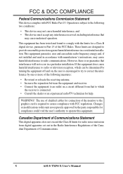
... television reception, which can radiate radio frequency energy and, if not installed and used in the Radio Interference Regulations of the Canadian Department of Communications. 6 ASUS TXP4-X User's Manual
... television reception, which can radiate radio frequency energy and, if not installed and used in the Radio Interference Regulations of the Canadian Department of Communications. 6 ASUS TXP4-X User's Manual
User Manual
Page 7
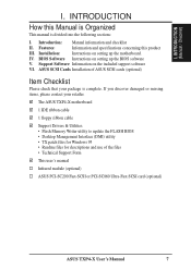
... Cards Installation of the files • Technical Support Form This user's manual Infrared module (optional) ASUS PCI-SC200 Fast-SCSI or PCI-SC860 Ultra-Fast SCSI card (optional) ASUS TXP4-X User's Manual 7 The ASUS TXP4-X motherboard 1 IDE ribbon cable 1 floppy ribbon cable Support Drivers & Utilities • Flash Memory Writer utility to update the FLASH BIOS...
... Cards Installation of the files • Technical Support Form This user's manual Infrared module (optional) ASUS PCI-SC200 Fast-SCSI or PCI-SC860 Ultra-Fast SCSI card (optional) ASUS TXP4-X User's Manual 7 The ASUS TXP4-X motherboard 1 IDE ribbon cable 1 floppy ribbon cable Support Drivers & Utilities • Flash Memory Writer utility to update the FLASH BIOS...
User Manual
Page 8
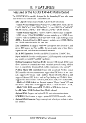
...168-pin 3.3Volt SDRAM/EDO memory modules up to communicate within a standard protocol creating a higher level of the ASUS TXP4-X Motherboard The ASUS TXP4-X is carefully designed for wireless interface. 8 ASUS TXP4-X User's Manual Supports Japanese "Floppy 3 mode" (3.5-inch disk drive: 1.2MB) and LS-120 floppy disk ...: Has firmware to 256MB. FEATURES (Features) II. BIOS supports IDE CD-ROM or SCSI device boot-up to support optional ASUS SCSI controller cards. • Optional IrDA Connector: Supports an optional infrared port module for the demanding PC user who wants many...
...168-pin 3.3Volt SDRAM/EDO memory modules up to communicate within a standard protocol creating a higher level of the ASUS TXP4-X Motherboard The ASUS TXP4-X is carefully designed for wireless interface. 8 ASUS TXP4-X User's Manual Supports Japanese "Floppy 3 mode" (3.5-inch disk drive: 1.2MB) and LS-120 floppy disk ...: Has firmware to 256MB. FEATURES (Features) II. BIOS supports IDE CD-ROM or SCSI device boot-up to support optional ASUS SCSI controller cards. • Optional IrDA Connector: Supports an optional infrared port module for the demanding PC user who wants many...
User Manual
Page 9
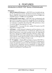
... are based on all system components, and 32-bit device drivers and installation procedures for both Windows 95 and Windows NT. ASUS TXP4-X User's Manual 9 ACPI (Advanced Configuration and Power Interface) is compatible with Intel 430TX PCIset improves IDE transfer rate using SDRAM... the future operating systems (OS) supporting OS Direct Power Management (OSPM) functionality. With these features implemented in the successor to ASUS TX97 Series of motherboards meet PC '97 compliancy. port the new generation memory, Synchronous Dynamic Random Access Memory (SDRAM), which can...
... are based on all system components, and 32-bit device drivers and installation procedures for both Windows 95 and Windows NT. ASUS TXP4-X User's Manual 9 ACPI (Advanced Configuration and Power Interface) is compatible with Intel 430TX PCIset improves IDE transfer rate using SDRAM... the future operating systems (OS) supporting OS Direct Power Management (OSPM) functionality. With these features implemented in the successor to ASUS TX97 Series of motherboards meet PC '97 compliancy. port the new generation memory, Synchronous Dynamic Random Access Memory (SDRAM), which can...
User Manual
Page 10
(This page is intentionally left blank.) 10 ASUS TXP4-X User's Manual
(This page is intentionally left blank.) 10 ASUS TXP4-X User's Manual
User Manual
Page 11
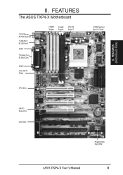
B: Serial Conn. II. COM 2 Intel's 430TX PCIset 4 SIMM Sockets 2 DIMM Sockets CPU ZIF Socket 7 3 PCI Slots 512KB Pipelined Burst L2 Cache ISA/PCI Shared Slot 3 ISA Slots Programmable Flash ROM ASUS TXP4-X User's Manual 11 FEATURES The ASUS TXP4-X Motherboard T: PS/2 Mouse B: PS/2 Keyboard T: USB Port 1 B: USB Port 2 COM 1 T: Parallel Conn. FEATURES (Motherboard Parts) II.
B: Serial Conn. II. COM 2 Intel's 430TX PCIset 4 SIMM Sockets 2 DIMM Sockets CPU ZIF Socket 7 3 PCI Slots 512KB Pipelined Burst L2 Cache ISA/PCI Shared Slot 3 ISA Slots Programmable Flash ROM ASUS TXP4-X User's Manual 11 FEATURES The ASUS TXP4-X Motherboard T: PS/2 Mouse B: PS/2 Keyboard T: USB Port 1 B: USB Port 2 COM 1 T: Parallel Conn. FEATURES (Motherboard Parts) II.
User Manual
Page 12
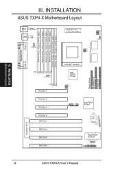
...R PCIset CR2032 3 Volt Lithium Cell BIOS Power FANPWR1 Flash ROM for ATX Power Supply CPU Voltage VID0 VID1 VID2 VID3 CPU Fan BUS Freq. INSTALLATION ASUS TXP4-X Motherboard Layout COM 1 PS/2 T: Mouse B: Keyboard USB T: USB 1 B: USB 2 FANPWR3 Board Power Input for BIOS Infrared Con. (IrDA) ...Panel Connections IDE LED RTC (Test/Clear) RTCLR Keyboard BIOS 12 ASUS TXP4-X User's Manual DIMM Socket 1 (64-bit, 168-pin module) DIMM Socket 2 (64-bit, 168-pin module) SIMM Socket 1 (32-bit, 72-pin...
...R PCIset CR2032 3 Volt Lithium Cell BIOS Power FANPWR1 Flash ROM for ATX Power Supply CPU Voltage VID0 VID1 VID2 VID3 CPU Fan BUS Freq. INSTALLATION ASUS TXP4-X Motherboard Layout COM 1 PS/2 T: Mouse B: Keyboard USB T: USB 1 B: USB 2 FANPWR3 Board Power Input for BIOS Infrared Con. (IrDA) ...Panel Connections IDE LED RTC (Test/Clear) RTCLR Keyboard BIOS 12 ASUS TXP4-X User's Manual DIMM Socket 1 (64-bit, 168-pin module) DIMM Socket 2 (64-bit, 168-pin module) SIMM Socket 1 (32-bit, 72-pin...
User Manual
Page 13
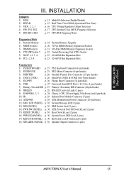
... LED Lead (3 pins) 17) KEYLOCK (PANEL) p. 30 Keyboard Lock Switch Lead (2 pins) 18) SPEAKER (PANEL) p. 30 Speaker Output Connector (4 pins) III. INSTALLATION (Map of Board) ASUS TXP4-X User's Manual 13
... LED Lead (3 pins) 17) KEYLOCK (PANEL) p. 30 Keyboard Lock Switch Lead (2 pins) 18) SPEAKER (PANEL) p. 30 Speaker Output Connector (4 pins) III. INSTALLATION (Map of Board) ASUS TXP4-X User's Manual 13
User Manual
Page 14
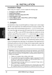
... as [----], [1-2], [2-3] for locations of jumpers. INSTALLATION Installation Steps Before using your computer when working on jumpers with the keyboard connector away from the system. 14 ASUS TXP4-X User's Manual Computer motherboards, baseboards and components, such as diagramed. Install Expansion Cards 5. tion, connect pins 1&2, and connect pins 2&3 respectively. To protect them against damage...
... as [----], [1-2], [2-3] for locations of jumpers. INSTALLATION Installation Steps Before using your computer when working on jumpers with the keyboard connector away from the system. 14 ASUS TXP4-X User's Manual Computer motherboards, baseboards and components, such as diagramed. Install Expansion Cards 5. tion, connect pins 1&2, and connect pins 2&3 respectively. To protect them against damage...
User Manual
Page 15
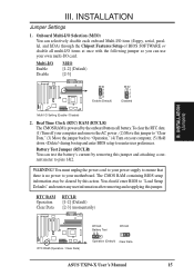
... jumper back to pins 1&2. RTC RAM RTCLR Operation [1-2] (Default) Clear Data [2-3] (momentarily) RTC RAM (Operation / Clear Data) RTCLR Battery Test RTCLR Operation (Default) Clear Data ASUS TXP4-X User's Manual 15 Onboard Multi-I/O Selection (M/IO) You can selectively disable each onboard Multi-I/O item (floppy, serial, parallel, and IrDA) through the Chipset Features Setup...
... jumper back to pins 1&2. RTC RAM RTCLR Operation [1-2] (Default) Clear Data [2-3] (momentarily) RTC RAM (Operation / Clear Data) RTCLR Battery Test RTCLR Operation (Default) Clear Data ASUS TXP4-X User's Manual 15 Onboard Multi-I/O Selection (M/IO) You can selectively disable each onboard Multi-I/O item (floppy, serial, parallel, and IrDA) through the Chipset Features Setup...
User Manual
Page 16
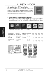
... on this motherboard is labeled Cyrix 6x86 PR166+ but must be Revision 2.7 or later. The voltage regulators will result in the same voltages, respectively. 16 ASUS TXP4-X User's Manual The number should read G8DC6620A or later. 3. INSTALLATION Compatible Cyrix CPU Identification The only Cyrix CPU that is supported on the underside of...
... on this motherboard is labeled Cyrix 6x86 PR166+ but must be Revision 2.7 or later. The voltage regulators will result in the same voltages, respectively. 16 ASUS TXP4-X User's Manual The number should read G8DC6620A or later. 3. INSTALLATION Compatible Cyrix CPU Identification The only Cyrix CPU that is supported on the underside of...
User Manual
Page 17
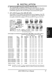
...). INSTALLATION (Jumpers) III. These allow the selection of the CPU and the External frequency (called the BUS Clock) within the CPU. CPU to the CPU. ASUS TXP4-X User's Manual 17 FS0 FS1 FS2 FS0 FS1 FS2 FS0 FS1 FS2 BF0 FS0 FS1 FS2 1 1 1 1 2 2 2 2 3 3 3 3 50MHz 55MHz 60MHz 66MHz CPU External Clock (BUS) Frequency...
...). INSTALLATION (Jumpers) III. These allow the selection of the CPU and the External frequency (called the BUS Clock) within the CPU. CPU to the CPU. ASUS TXP4-X User's Manual 17 FS0 FS1 FS2 FS0 FS1 FS2 FS0 FS1 FS2 BF0 FS0 FS1 FS2 1 1 1 1 2 2 2 2 3 3 3 3 50MHz 55MHz 60MHz 66MHz CPU External Clock (BUS) Frequency...
User Manual
Page 18
(This page was left intentionally blank.) 18 ASUS TXP4-X User's Manual
(This page was left intentionally blank.) 18 ASUS TXP4-X User's Manual
User Manual
Page 19
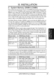
... memory. If both SIMMs and DIMMs at the same time or else you will be empty) Total System Memory (Max 256MB) Total Memory x1 x1 = ASUS TXP4-X User's Manual 19 System Memory (SIMM & DIMM) This motherboard supports four 72-pin, 32-bit SIMMs (Single Inline Memory Modules) of either 8, 16, 32, 64...
... memory. If both SIMMs and DIMMs at the same time or else you will be empty) Total System Memory (Max 256MB) Total Memory x1 x1 = ASUS TXP4-X User's Manual 19 System Memory (SIMM & DIMM) This motherboard supports four 72-pin, 32-bit SIMMs (Single Inline Memory Modules) of either 8, 16, 32, 64...
User Manual
Page 20
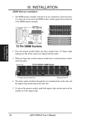
... the sides and the support clips should snap on one end of the SIMM sockets, which requires the notched end of the support clips. 20 ASUS TXP4-X User's Manual R III. INSTALLATION (System Memory) III.
... the sides and the support clips should snap on one end of the SIMM sockets, which requires the notched end of the support clips. 20 ASUS TXP4-X User's Manual R III. INSTALLATION (System Memory) III.
User Manual
Page 21
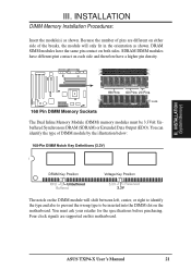
DRAM SIMM modules have a higher pin density. Four clock signals are different on this motherboard. ASUS TXP4-X User's Manual 21 Because the number of pins are supported on either side of DIMM module by the illustration below: 168-Pin DIMM Notch Key ...
DRAM SIMM modules have a higher pin density. Four clock signals are different on this motherboard. ASUS TXP4-X User's Manual 21 Because the number of pins are supported on either side of DIMM module by the illustration below: 168-Pin DIMM Notch Key ...


