
User Manual
Page 1
IMPORTANT: This preliminary copy is for review purposes only and is subject to errors and ongoing modifications. R TX97-XV Pentium® ATX Motherboard USER'S MANUAL
IMPORTANT: This preliminary copy is for review purposes only and is subject to errors and ongoing modifications. R TX97-XV Pentium® ATX Motherboard USER'S MANUAL
User Manual
Page 4
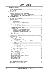
...Unit (CPU 23 4. INTRODUCTION 7 How this manual is organized 7 Item Checklist 7 II. FEATURES 8 Features of the ASUS TX97-XV Motherboard 8 Introduction to ASUS TX97 Series of motherboards 9 Parts of PNP and PCI Setup 50 Load BIOS Defaults 52 Load Setup Defaults 52 Supervisor Password and User Password 53... 48 Details of Power Management Setup 48 PNP and PCI Setup 50 Details of the ASUS TX97-XV Motherboard 11 III. SUPPORT SOFTWARE 56 ASUS TX97 Motherboard Series Support CD 56 LANDesk Client Manager (LDCM 56 4 ASUS TX97-XV User's Manual CONTENTS I. INSTALLATION 12 Map of the...
...Unit (CPU 23 4. INTRODUCTION 7 How this manual is organized 7 Item Checklist 7 II. FEATURES 8 Features of the ASUS TX97-XV Motherboard 8 Introduction to ASUS TX97 Series of motherboards 9 Parts of PNP and PCI Setup 50 Load BIOS Defaults 52 Load Setup Defaults 52 Supervisor Password and User Password 53... 48 Details of Power Management Setup 48 PNP and PCI Setup 50 Details of the ASUS TX97-XV Motherboard 11 III. SUPPORT SOFTWARE 56 ASUS TX97 Motherboard Series Support CD 56 LANDesk Client Manager (LDCM 56 4 ASUS TX97-XV User's Manual CONTENTS I. INSTALLATION 12 Map of the...

User Manual
Page 7
...descriptions and use of the files • Technical Support Form √ This user's manual Optional ASUS I -A16C bundle) Item Checklist Please check that your retailer. √ The ASUS TX97-XV motherboard √ 1 serial port ribbon cable attached to a mounting bracket √ 1 IDE ribbon ...cable √ 1 floppy ribbon cable √ ASUS TX97 Series Support CD: • LANDesk Client Manager (LDCM) Software...
...descriptions and use of the files • Technical Support Form √ This user's manual Optional ASUS I -A16C bundle) Item Checklist Please check that your retailer. √ The ASUS TX97-XV motherboard √ 1 serial port ribbon cable attached to a mounting bracket √ 1 IDE ribbon ...cable √ 1 floppy ribbon cable √ ASUS TX97 Series Support CD: • LANDesk Client Manager (LDCM) Software...
User Manual
Page 8
...'s Manual This controller supports PIO Modes 3 and 4 and Bus Master IDE DMA Mode 2. II. Two floppy drives of the ASUS TX97-XV Motherboard The ASUS TX97-XV is carefully designed for wireless connections. FEATURES (Features) II. SIMMs and DIMMs cannot be directed from COM2 to make setup of ... also be used at the same time. • Easy Installation: Is equipped with BIOS that supports four IDE devices in a small package. This motherboard: • Intel Chipset: Features Intel's 430TX PCIset with I /O: Provides two high-speed UART compatible serial ports and one parallel port with two ...
...'s Manual This controller supports PIO Modes 3 and 4 and Bus Master IDE DMA Mode 2. II. Two floppy drives of the ASUS TX97-XV Motherboard The ASUS TX97-XV is carefully designed for wireless connections. FEATURES (Features) II. SIMMs and DIMMs cannot be directed from COM2 to make setup of ... also be used at the same time. • Easy Installation: Is equipped with BIOS that supports four IDE devices in a small package. This motherboard: • Intel Chipset: Features Intel's 430TX PCIset with I /O: Provides two high-speed UART compatible serial ports and one parallel port with two ...
User Manual
Page 9
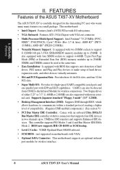
... and power management for its normal RPM range and alarm thresholds. • Temperature Monitoring and Alert - ASUS TX97-XV User's Manual 9 ACPI (Advanced Configuration and Power Interface) is compatible with Intel 430TX PCIset improves IDE ...ASUS 430TX series of motherboards Performance: • SDRAM Optimized Performance - ASUS TX97 series of motherboards with existing ATA-2 IDE specs so there is operating at a safe heat level to ASUS TX97 Series of motherboards. Both the BIOS and hardware levels of ASUS TX97 series of motherboards sup- ASUS TX97 series of motherboards...
... and power management for its normal RPM range and alarm thresholds. • Temperature Monitoring and Alert - ASUS TX97-XV User's Manual 9 ACPI (Advanced Configuration and Power Interface) is compatible with Intel 430TX PCIset improves IDE ...ASUS 430TX series of motherboards Performance: • SDRAM Optimized Performance - ASUS TX97 series of motherboards with existing ATA-2 IDE specs so there is operating at a safe heat level to ASUS TX97 Series of motherboards. Both the BIOS and hardware levels of ASUS TX97 series of motherboards sup- ASUS TX97 series of motherboards...
User Manual
Page 10
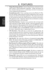
... operating systems such as Windows 95, Windows NT, and OS/2, require much more efficiently. • Virus Write Protection - ASUS TX97 series of motherboards were designed to cooperate with BIOS, chipset, and flash EPROM to disable write permission when the system's initialization stage is a.... FEATURES • Voltage Monitoring and Alert - Normally, viruses can determine the stage the computer is necessary to the user. 10 ASUS TX97-XV User's Manual Some new-generation viruses will warn the user before the system resources are monitored to ensure stable current to prevent possible...
... operating systems such as Windows 95, Windows NT, and OS/2, require much more efficiently. • Virus Write Protection - ASUS TX97 series of motherboards were designed to cooperate with BIOS, chipset, and flash EPROM to disable write permission when the system's initialization stage is a.... FEATURES • Voltage Monitoring and Alert - Normally, viruses can determine the stage the computer is necessary to the user. 10 ASUS TX97-XV User's Manual Some new-generation viruses will warn the user before the system resources are monitored to ensure stable current to prevent possible...
User Manual
Page 11
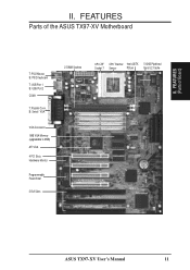
B: Serial / VGA VGA Connector 1MB VGA Memory (upgradable to 2MB) ATI VGA 4 PCI Slots Hardware Monitor Programmable Flash ROM 3 ISA Slots 2 DIMM Sockets CPU ZIF CPU Thermal Intel 430TX 512KB Pipelined Socket 7 Sensor PCIset Burst L2 Cache ASUS TX97-XV User's Manual 11 II. FEATURES Parts of Board) II. FEATURES (Parts of the ASUS TX97-XV Motherboard T: PS/2 Mouse B: PS/2 Keyboard T: USB Port 1 B: USB Port 2 COM 1 T: Parallel Conn.
B: Serial / VGA VGA Connector 1MB VGA Memory (upgradable to 2MB) ATI VGA 4 PCI Slots Hardware Monitor Programmable Flash ROM 3 ISA Slots 2 DIMM Sockets CPU ZIF CPU Thermal Intel 430TX 512KB Pipelined Socket 7 Sensor PCIset Burst L2 Cache ASUS TX97-XV User's Manual 11 II. FEATURES Parts of Board) II. FEATURES (Parts of the ASUS TX97-XV Motherboard T: PS/2 Mouse B: PS/2 Keyboard T: USB Port 1 B: USB Port 2 COM 1 T: Parallel Conn.
User Manual
Page 12
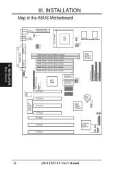
... VID1 VID0 CPU Voltage CPU ZIF Socket 7 Heat Sensor CPU_FAN 256KB/512KB Onboard L2 Cache FREQ. INSTALLATION Map of Board) III. INSTALLATION (Map of the ASUS Motherboard Parallel Port PS/2 T: Mouse B: Keyboard Board Power Input for BIOS PCI Slot 1 PCI Slot 2 PCI Slot 3 PCI Slot 4 ISA Slot 1 512KB DRAM 512KB DRAM CR2032... Intel PIIX4 PCIset RTCLR RTC (Clear/Test) IDE LED Panel Connections Infrared Con. ISA Slot 2 ISA Slot 3 Keyboard BIOS/ Multi-I/O Chassis open CHASSIS FAN 12 ASUS TX97-XV User's Manual III.
... VID1 VID0 CPU Voltage CPU ZIF Socket 7 Heat Sensor CPU_FAN 256KB/512KB Onboard L2 Cache FREQ. INSTALLATION Map of Board) III. INSTALLATION (Map of the ASUS Motherboard Parallel Port PS/2 T: Mouse B: Keyboard Board Power Input for BIOS PCI Slot 1 PCI Slot 2 PCI Slot 3 PCI Slot 4 ISA Slot 1 512KB DRAM 512KB DRAM CR2032... Intel PIIX4 PCIset RTCLR RTC (Clear/Test) IDE LED Panel Connections Infrared Con. ISA Slot 2 ISA Slot 3 Keyboard BIOS/ Multi-I/O Chassis open CHASSIS FAN 12 ASUS TX97-XV User's Manual III.
User Manual
Page 13
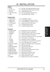
... Switch Lead (2-pins) p. 31 Reset Switch Lead (2-pins) p. 31 Keyboard Lock Switch Lead (5-pins) p. 31 Speaker Output Connector (4-pins) p. 32 Infrared Port Module Connector p. 32 Motherboard Power Connector (20-pin Block) ASUS TX97-XV User's Manual 13
... Switch Lead (2-pins) p. 31 Reset Switch Lead (2-pins) p. 31 Keyboard Lock Switch Lead (5-pins) p. 31 Speaker Output Connector (4-pins) p. 32 Infrared Port Module Connector p. 32 Motherboard Power Connector (20-pin Block) ASUS TX97-XV User's Manual 13
User Manual
Page 14
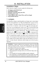
...ASUS TX97-XV User's Manual For manufacturing simplicity, the jumpers may be shown as [----], [1-2], [2-3] for no connection, connect pins 1&2, and connect pins 2&3 respec- To connect the pins, simply place a plastic jumper cap over the two pins as to connect pins 1&2 and to touch the IC chips, leads, or circuitry. 3. To protect the motherboard.... 4. Install DRAM Modules 3. Pin 1 Pin 1 tively. Use the diagrams in this manual instead of the Motherboard" on jumpers with the component whenever the components are made through the use of jumpers. Unplug your computer. 1....
...ASUS TX97-XV User's Manual For manufacturing simplicity, the jumpers may be shown as [----], [1-2], [2-3] for no connection, connect pins 1&2, and connect pins 2&3 respec- To connect the pins, simply place a plastic jumper cap over the two pins as to connect pins 1&2 and to touch the IC chips, leads, or circuitry. 3. To protect the motherboard.... 4. Install DRAM Modules 3. Pin 1 Pin 1 tively. Use the diagrams in this manual instead of the Motherboard" on jumpers with the component whenever the components are made through the use of jumpers. Unplug your computer. 1....

User Manual
Page 15
To clear the RTC data: (1) Turn off your computer, (2) Move this jumper and attaching a current meter to "Operation," (4) Turn on your motherboard. The CMOS RAM containing BIOS setup information may be cleared by removing this jumper to "Clear Data," (3) Move the jumper back to pins 2&3. Battery Test .... WARNING: You must unplug the power cord to your power supply to ensure that there is powered by the onboard button cell battery. INSTALLATION (Jumpers) ASUS TX97-XV User's Manual 15 INSTALLATION Jumper Settings 1.
To clear the RTC data: (1) Turn off your computer, (2) Move this jumper and attaching a current meter to "Operation," (4) Turn on your motherboard. The CMOS RAM containing BIOS setup information may be cleared by removing this jumper to "Clear Data," (3) Move the jumper back to pins 2&3. Battery Test .... WARNING: You must unplug the power cord to your power supply to ensure that there is powered by the onboard button cell battery. INSTALLATION (Jumpers) ASUS TX97-XV User's Manual 15 INSTALLATION Jumper Settings 1.
User Manual
Page 16
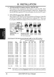
... tell the clock generator what frequency to send to BUS Frequency Ratio (BF0, BF1) These jumpers set together with the Cyrix 166+ installed on this motherboard. 16 ASUS TX97-XV User's Manual CPU to the CPU. INSTALLATION (Jumpers) Complete Names: Intel Pentium P54C, P55C AMD K5, K6 Cyrix M1, M2 P54C/K5 1.5x(3/2) 2.0x...
... tell the clock generator what frequency to send to BUS Frequency Ratio (BF0, BF1) These jumpers set together with the Cyrix 166+ installed on this motherboard. 16 ASUS TX97-XV User's Manual CPU to the CPU. INSTALLATION (Jumpers) Complete Names: Intel Pentium P54C, P55C AMD K5, K6 Cyrix M1, M2 P54C/K5 1.5x(3/2) 2.0x...
User Manual
Page 17
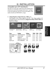
... VID1 VID0 VID2 VID1 VID0 VID2 VID1 VID0 VID2 VID1 VID0 Voltage Regulator Output Selection 1 2 3 3.5Volts (VRE) 1 2 3 2.8Volts 1 2 3 3.4Volts (STD) 1 2 3 2.7Volts 1 2 3 3.2Volts 1 2 3 2.5Volts 1 2 3 2.9Volts ASUS TX97-XV User's Manual 17 III. INSTALLATION (System Memory) III. The number should read G8DC6620A or larger. 4. The voltage regulators will automatically detect and switch between Single... only Cyrix CPU that is labeled Cyrix 6x86 P166+ but must be Revision 2.7 and later. Look on this motherboard is supported on the underside of the CPU for the serial number.
... VID1 VID0 VID2 VID1 VID0 VID2 VID1 VID0 VID2 VID1 VID0 Voltage Regulator Output Selection 1 2 3 3.5Volts (VRE) 1 2 3 2.8Volts 1 2 3 3.4Volts (STD) 1 2 3 2.7Volts 1 2 3 3.2Volts 1 2 3 2.5Volts 1 2 3 2.9Volts ASUS TX97-XV User's Manual 17 III. INSTALLATION (System Memory) III. The number should read G8DC6620A or larger. 4. The voltage regulators will automatically detect and switch between Single... only Cyrix CPU that is labeled Cyrix 6x86 P166+ but must be Revision 2.7 and later. Look on this motherboard is supported on the underside of the CPU for the serial number.
User Manual
Page 19
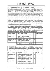
...a memory size between 8MB to 256MB. SIMMs must be installed in BIOS Chipset Setup of the DIMM module takes up half a Row on the motherboard. One side (with more than 24 chips exceed the design specifications of memory chips. Memory Socket DIMM Socket 1 (Rows 3 & 2) DIMM ... 16MB, 32MB, 64MB, 128MB 168-pin SDRAM or EDO DIMM (SIMM Sockets must be empty) Total System Memory (Max 256MB) Total Memory x1 x1 = ASUS TX97-XV User's Manual 19 III. Two sockets are currently unavailable. Memory Socket SIMM Sockets 1&2 (Rows 0 & 1) SIMM Sockets 3&4 (Rows 2 & 3) SIMM Memory...
...a memory size between 8MB to 256MB. SIMMs must be installed in BIOS Chipset Setup of the DIMM module takes up half a Row on the motherboard. One side (with more than 24 chips exceed the design specifications of memory chips. Memory Socket DIMM Socket 1 (Rows 3 & 2) DIMM ... 16MB, 32MB, 64MB, 128MB 168-pin SDRAM or EDO DIMM (SIMM Sockets must be empty) Total System Memory (Max 256MB) Total Memory x1 x1 = ASUS TX97-XV User's Manual 19 III. Two sockets are currently unavailable. Memory Socket SIMM Sockets 1&2 (Rows 0 & 1) SIMM Sockets 3&4 (Rows 2 & 3) SIMM Memory...
User Manual
Page 21
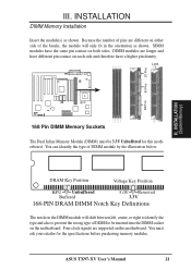
...) 88 Pins 168 Pin DIMM Memory Sockets The Dual Inline Memory Module (DIMM) must ask your retailer for this motherboard. ASUS TX97-XV User's Manual 21 Because the number of pins are supported on the motherboard. INSTALLATION DIMM Memory Installation Insert the module(s) as shown. Lock 60 Pins 20 Pins III. You can identify the... will only fit in the orientation as shown. SIMM modules have a higher pin density. III. You must be inserted into the DIMM socket on this motherboard.
...) 88 Pins 168 Pin DIMM Memory Sockets The Dual Inline Memory Module (DIMM) must ask your retailer for this motherboard. ASUS TX97-XV User's Manual 21 Because the number of pins are supported on the motherboard. INSTALLATION DIMM Memory Installation Insert the module(s) as shown. Lock 60 Pins 20 Pins III. You can identify the... will only fit in the orientation as shown. SIMM modules have a higher pin density. III. You must be inserted into the DIMM socket on this motherboard.

User Manual
Page 23
...no force is missing from the socket then upwards to a 90-degree right angle. With the added weight of the CPU with Pentium Processor ASUS TX97-XV User's Manual 23 INSTALLATION (CPU) Lever Lock White Dot 1 Blank 1 ZIF Socket 7 with the white dot as your guide. Insert the...CPU. The white dot should have a CPU fan that is backwards compatible with the correct orientation as shown. Central Processing Unit (CPU) The motherboard provides a 321-pin ZIF Socket 7 that will only fit in the one hole is required to prevent overheating. If this section.) To install...
...no force is missing from the socket then upwards to a 90-degree right angle. With the added weight of the CPU with Pentium Processor ASUS TX97-XV User's Manual 23 INSTALLATION (CPU) Lever Lock White Dot 1 Blank 1 ZIF Socket 7 with the white dot as your guide. Insert the...CPU. The white dot should have a CPU fan that is backwards compatible with the correct orientation as shown. Central Processing Unit (CPU) The motherboard provides a 321-pin ZIF Socket 7 that will only fit in the one hole is required to prevent overheating. If this section.) To install...

User Manual
Page 24
...Interrupt number and address. Make sure that may use Microsoft's Diagnostic (MSD.EXE) utility included in use at the same time. 24 ASUS TX97-XV User's Manual Replace the computer system's cover. 8. Generally an IRQ must be required to cards installed in use by PCI cards. ...Cards) Expansion Card Installation Procedure: 1. In an standard design there are 16 IRQs available but most of them are two types of your motherboard and expansion cards. Double clicking on the slot with the screw you unplug your computer system's cover. 4. Expansion Cards WARNING: Make sure ...
...Interrupt number and address. Make sure that may use Microsoft's Diagnostic (MSD.EXE) utility included in use at the same time. 24 ASUS TX97-XV User's Manual Replace the computer system's cover. 8. Generally an IRQ must be required to cards installed in use by PCI cards. ...Cards) Expansion Card Installation Procedure: 1. In an standard design there are 16 IRQs available but most of them are two types of your motherboard and expansion cards. Double clicking on the slot with the screw you unplug your computer system's cover. 4. Expansion Cards WARNING: Make sure ...

User Manual
Page 25
... are assigned automatically from those used by Legacy cards. Since all the PCI slots on this motherboard use a DMA (Direct Memory Access) channel. DMA assignments for this motherboard has complied with the BIOS, you wish to reserve for an ISA Configuration Utility. An IRQ.... To install a PCI card, you need to INT A. INSTALLATION To simplify this process this motherboard are set something called the INT (interrupt) assignment. III. INSTALLATION (D(CMoAnCnhecatnonrsel)s) ASUS TX97-XV User's Manual 25 The PCI and PNP configuration of the BIOS Setup utility. For PNP cards,...
... are assigned automatically from those used by Legacy cards. Since all the PCI slots on this motherboard use a DMA (Direct Memory Access) channel. DMA assignments for this motherboard has complied with the BIOS, you wish to reserve for an ISA Configuration Utility. An IRQ.... To install a PCI card, you need to INT A. INSTALLATION To simplify this process this motherboard are set something called the INT (interrupt) assignment. III. INSTALLATION (D(CMoAnCnhecatnonrsel)s) ASUS TX97-XV User's Manual 25 The PCI and PNP configuration of the BIOS Setup utility. For PNP cards,...

User Manual
Page 26
... Connectors WARNING: Some pins are used for a standard keyboard using an PS/2 plug (mini DIN). This connector will cause damage to your motherboard. If not detected, expansion cards can use a DIN to the power connector on the Pin 1 side of the BIOS SOFTWARE. INSTALLATION (...drives. PS/2 Mouse (6-pin Female) 26 ASUS TX97-XV User's Manual Placing jumper caps over these will not allow standard AT size (large DIN) keyboard plugs. PS/2 Keyboard (6-pin Female) 2. These are labeled on standard AT keyboards. The four corners of the Motherboard." See "PS/2 Mouse Control" in "...
... Connectors WARNING: Some pins are used for a standard keyboard using an PS/2 plug (mini DIN). This connector will cause damage to your motherboard. If not detected, expansion cards can use a DIN to the power connector on the Pin 1 side of the BIOS SOFTWARE. INSTALLATION (...drives. PS/2 Mouse (6-pin Female) 26 ASUS TX97-XV User's Manual Placing jumper caps over these will not allow standard AT size (large DIN) keyboard plugs. PS/2 Keyboard (6-pin Female) 2. These are labeled on standard AT keyboards. The four corners of the Motherboard." See "PS/2 Mouse Control" in "...

User Manual
Page 29
...or less. Orientate the fans so that the heat sink fins allow airflow to the system that air flow runs across motherboard's heatsinks. 9. WARNING: The CPU and/or motherboard will indicate to go across the CPU and onboard heatsinks. Chassis open chassis monitor. These are incorrectly used only by...) This lead is to the motherboard and/or the CPU fan if these pins are not jumpers, do not place jumper caps over these pins. INSTALLATION (Connectors) III. NOTE: The "Rotation" signal is for an open alarm lead +5V GND CHASSIS ASUS TX97-XV User's Manual 29 Chassis Fan ...
...or less. Orientate the fans so that the heat sink fins allow airflow to the system that air flow runs across motherboard's heatsinks. 9. WARNING: The CPU and/or motherboard will indicate to go across the CPU and onboard heatsinks. Chassis open chassis monitor. These are incorrectly used only by...) This lead is to the motherboard and/or the CPU fan if these pins are not jumpers, do not place jumper caps over these pins. INSTALLATION (Connectors) III. NOTE: The "Rotation" signal is for an open alarm lead +5V GND CHASSIS ASUS TX97-XV User's Manual 29 Chassis Fan ...


