TX97-N User Manual
Page 1
R TX97-N Pentium® NLX Motherboard USER'S MANUAL
R TX97-N Pentium® NLX Motherboard USER'S MANUAL
TX97-N User Manual
Page 4
...Utility 32 Advanced Features Menu 33 Managing and Updating Your Motherboard's BIOS 34 6. INSTALLATION 10 ASUS TX97-N Motherboard Layout 10 Installation Steps 12 1. Central Processing Unit (CPU 19 4. FEATURES 8 Features of the ASUS TX97-N Motherboard 8 Parts of Power Management Setup 44 4 ASUS TX97-N User's Manual System Memory (DIMM 17 DIMM Memory Installation...Features Setup 41 Details of Chipset Features Setup 41 Power Management Setup 44 Details of the ASUS TX97-N Motherboard 9 Riser Card Front 9 Riser Card Back 9 III. Jumpers 12 Jumper Settings 13 2. CONTENTS I.
...Utility 32 Advanced Features Menu 33 Managing and Updating Your Motherboard's BIOS 34 6. INSTALLATION 10 ASUS TX97-N Motherboard Layout 10 Installation Steps 12 1. Central Processing Unit (CPU 19 4. FEATURES 8 Features of the ASUS TX97-N Motherboard 8 Parts of Power Management Setup 44 4 ASUS TX97-N User's Manual System Memory (DIMM 17 DIMM Memory Installation...Features Setup 41 Details of Chipset Features Setup 41 Power Management Setup 44 Details of the ASUS TX97-N Motherboard 9 Riser Card Front 9 Riser Card Back 9 III. Jumpers 12 Jumper Settings 13 2. CONTENTS I.
TX97-N User Manual
Page 7
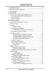
...) VII. Features: Information and specifications concerning this manual is organized This manual is complete. ASUS SCSI Cards: Installation of the ASUS LAN card (optional) Item Checklist Please check that your retailer. (1) ASUS motherboard (1) IDE ribbon cable for master and slave drives (1) Floppy ribbon cable for one 3.5inch...-L101 Wake-on setting up the BIOS software V. Installation: Instructions on -LAN 10/100 Ethernet Card (optional) ASUS TX97-N User's Manual 7 If you discover damaged or missing items, please contact your package is divided into the following ...
...) VII. Features: Information and specifications concerning this manual is organized This manual is complete. ASUS SCSI Cards: Installation of the ASUS LAN card (optional) Item Checklist Please check that your retailer. (1) ASUS motherboard (1) IDE ribbon cable for master and slave drives (1) Floppy ribbon cable for one 3.5inch...-L101 Wake-on setting up the BIOS software V. Installation: Instructions on -LAN 10/100 Ethernet Card (optional) ASUS TX97-N User's Manual 7 If you discover damaged or missing items, please contact your package is divided into the following ...
TX97-N User Manual
Page 8
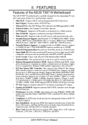
...2MB) and LS-120 floppy disk drives (3.5-inch disk drive: 120 MB, 1.44MB, 720K). FEATURES (Features) II. II. FEATURES Features of the ASUS TX97-N Motherboard The ASUS TX97-N motherboard is carefully designed for the demanding PC user who wants many features in a small package, namely: • Mini NLX: Features... ASUS' custom designed mini-NLX form factor. • Intel Chipset: Features Intel's 430TX PCIset. • Onboard VGA: Has ATI 3D ...
...2MB) and LS-120 floppy disk drives (3.5-inch disk drive: 120 MB, 1.44MB, 720K). FEATURES (Features) II. II. FEATURES Features of the ASUS TX97-N Motherboard The ASUS TX97-N motherboard is carefully designed for the demanding PC user who wants many features in a small package, namely: • Mini NLX: Features... ASUS' custom designed mini-NLX form factor. • Intel Chipset: Features Intel's 430TX PCIset. • Onboard VGA: Has ATI 3D ...
TX97-N User Manual
Page 9
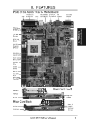
FEATURES (Motherboard Parts) T: PS/2 Mouse B: PS/2 Keyboard LCD Panel Connector ATI 3D Rage Chipset Intel CPU Compatible ZIF Socket 7 VGA Memory Upgrade Sockets 512KB Pipelined Burst L2 ... NLX Slot Riser Card Back IrDA Port 2 USB Ports Riser Card Front Floppy Drive Connector Primary IDE Connector NLX Power Connector ASUS TX97-N User's Manual 9 TV Out S-Video TV Out RCA VGA COM 1 B: Serial Conn. COM 2 Conn.(optional) Conn.(optional) Connector Joystick/MIDI Connector II. FEATURES Parts of the ASUS TX97-N Motherboard T: Parallel Conn. II.
FEATURES (Motherboard Parts) T: PS/2 Mouse B: PS/2 Keyboard LCD Panel Connector ATI 3D Rage Chipset Intel CPU Compatible ZIF Socket 7 VGA Memory Upgrade Sockets 512KB Pipelined Burst L2 ... NLX Slot Riser Card Back IrDA Port 2 USB Ports Riser Card Front Floppy Drive Connector Primary IDE Connector NLX Power Connector ASUS TX97-N User's Manual 9 TV Out S-Video TV Out RCA VGA COM 1 B: Serial Conn. COM 2 Conn.(optional) Conn.(optional) Connector Joystick/MIDI Connector II. FEATURES Parts of the ASUS TX97-N Motherboard T: Parallel Conn. II.

TX97-N User Manual
Page 10
...Card Front Riser Slot Riser Slot Floppy Drive Conn. Panel Conn. Infrared USB1&2 Riser Card Back Primary IDE NLX Power 10 ASUS TX97-N User's Manual INSTALLATION (Motherboard Layout) R CDROM Connector 512KB Pipelined Burst L2 Cache Intel 430TX PCIset Intel PIIX4 PCIset Multi I/O Chip Flash EEPROM (Programable... RTCLR CMOS Power CR2032 3 Volt Cell PCI Slot 2 PCI Slot 1 ISA Slot 1 LAN LED Wake on LAN NLX Ext. III. INSTALLATION ASUS TX97-N Motherboard Layout Parallel Port COM 1 COM 2 PS/2 SVHS TV Out RCA TV Out (TV Out is optional) MOUSE (TOP PORT) KEYBOARD (BOTTOM...
...Card Front Riser Slot Riser Slot Floppy Drive Conn. Panel Conn. Infrared USB1&2 Riser Card Back Primary IDE NLX Power 10 ASUS TX97-N User's Manual INSTALLATION (Motherboard Layout) R CDROM Connector 512KB Pipelined Burst L2 Cache Intel 430TX PCIset Intel PIIX4 PCIset Multi I/O Chip Flash EEPROM (Programable... RTCLR CMOS Power CR2032 3 Volt Cell PCI Slot 2 PCI Slot 1 ISA Slot 1 LAN LED Wake on LAN NLX Ext. III. INSTALLATION ASUS TX97-N Motherboard Layout Parallel Port COM 1 COM 2 PS/2 SVHS TV Out RCA TV Out (TV Out is optional) MOUSE (TOP PORT) KEYBOARD (BOTTOM...
TX97-N User Manual
Page 11
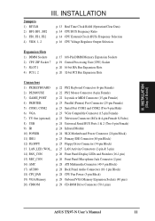
...23 Television Connector (RCA & 4-pin Female S-Video) p. 24 Universal Serial BUS Ports 1 & 2 (Two 4-pin Female) p. 24 Infrared Module p. 24 NLX Motherboard Power Connector (20-pin Block) p. 25 Primary IDE Connector (40-pin Block) p. 25 Floppy Drive Connector (34-pin Block) p. 25 LAN Activity Connectors (2-pin... pin Block) p. 28 CPU Fan Power (3-pin Block) p. 29 Onboard VGA Memory Expansion Sockets (40 pins) p. 29 CD-ROM Drive Connector (50-1 pins) ASUS TX97-N User's Manual 11 INSTALLATION Jumpers 1) RTCLR 2) BF0, BF1, BF2 3) FS0, FS1, FS2 4) VID0, 1, 2 p. 13 Real Time Clock RAM (Operation/...
...23 Television Connector (RCA & 4-pin Female S-Video) p. 24 Universal Serial BUS Ports 1 & 2 (Two 4-pin Female) p. 24 Infrared Module p. 24 NLX Motherboard Power Connector (20-pin Block) p. 25 Primary IDE Connector (40-pin Block) p. 25 Floppy Drive Connector (34-pin Block) p. 25 LAN Activity Connectors (2-pin... pin Block) p. 28 CPU Fan Power (3-pin Block) p. 29 Onboard VGA Memory Expansion Sockets (40 pins) p. 29 CD-ROM Drive Connector (50-1 pins) ASUS TX97-N User's Manual 11 INSTALLATION Jumpers 1) RTCLR 2) BF0, BF1, BF2 3) FS0, FS1, FS2 4) VID0, 1, 2 p. 13 Real Time Clock RAM (Operation/...
TX97-N User Manual
Page 12
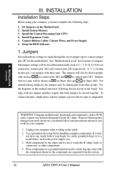
... are separated from the system. 12 ASUS TX97-N User's Manual The jumpers will also be sharing pins from static electricity, you should follow some precautions whenever you work on your computer when working on the inside. 2. Computer motherboards, baseboards and components, such as diagramed...Connect Ribbon Cables, Cabinet Wires, and Power Supply 6. To protect them against damage from other components. 4. III. Set Jumpers on the motherboard. The jumper settings will be shown as to connect pins 1&2 and to touch the IC chips, leads or connectors, or other groups...
... are separated from the system. 12 ASUS TX97-N User's Manual The jumpers will also be sharing pins from static electricity, you should follow some precautions whenever you work on your computer when working on the inside. 2. Computer motherboards, baseboards and components, such as diagramed...Connect Ribbon Cables, Cabinet Wires, and Power Supply 6. To protect them against damage from other components. 4. III. Set Jumpers on the motherboard. The jumper settings will be shown as to connect pins 1&2 and to touch the IC chips, leads or connectors, or other groups...
TX97-N User Manual
Page 13
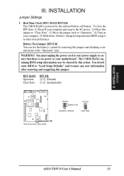
... should enter BIOS to "Load Setup Defaults" and re-enter any user information after removing and reapplying this jumper and attaching a current meter to your motherboard. INSTALLATION Jumper Settings 1. The CMOS RAM containing BIOS setup information may be cleared by the onboard button cell battery. Real Time Clock (RTC) RAM (RTCLR... computer, (5) Hold down during bootup and enter BIOS setup to "Operation," (4) Turn on your computer and remove the AC power , (2) Move this action. INSTALLATION (Jumpers) ASUS TX97-N User's Manual 13
... should enter BIOS to "Load Setup Defaults" and re-enter any user information after removing and reapplying this jumper and attaching a current meter to your motherboard. INSTALLATION Jumper Settings 1. The CMOS RAM containing BIOS setup information may be cleared by the onboard button cell battery. Real Time Clock (RTC) RAM (RTCLR... computer, (5) Hold down during bootup and enter BIOS setup to "Operation," (4) Turn on your computer and remove the AC power , (2) Move this action. INSTALLATION (Jumpers) ASUS TX97-N User's Manual 13
TX97-N User Manual
Page 15
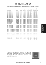
... Internal speed of the CPU for the serial number. Look on this motherboard is supported on the underside of the Intel, AMD, IBM, or ... A-1.5x A-1.5x A-1.5x BUS F. 66MHz 60MHz 66MHz 60MHz 66MHz 60MHz 50MHz (BUS Freq.) FS2 FS1 FS0 [1-2] [1-2] [1-2] [1-2] [1-2] [2-3] [1-2] [1-2] [1-2] [1-2] [1-2] [2-3] [1-2] [1-2] [1-2] [1-2] [1-2] [2-3] [2-3] [2-3] [2-3] (Freq. ASUS TX97-N User's Manual 15 INSTALLATION (Jumpers) *NOTE: The only IBM/Cyrix 6x86(L) (or M1) that is rev 2.7 or later. Ratio) BF2 BF1 BF0 [1-2] [2-3] [2-3] [1-2] [2-3] [2-3] [1-2] [1-2] [2-3] [1-2] [1-2] [2-3] [1-2] [1-2]...
... Internal speed of the CPU for the serial number. Look on this motherboard is supported on the underside of the Intel, AMD, IBM, or ... A-1.5x A-1.5x A-1.5x BUS F. 66MHz 60MHz 66MHz 60MHz 66MHz 60MHz 50MHz (BUS Freq.) FS2 FS1 FS0 [1-2] [1-2] [1-2] [1-2] [1-2] [2-3] [1-2] [1-2] [1-2] [1-2] [1-2] [2-3] [1-2] [1-2] [1-2] [1-2] [1-2] [2-3] [2-3] [2-3] [2-3] (Freq. ASUS TX97-N User's Manual 15 INSTALLATION (Jumpers) *NOTE: The only IBM/Cyrix 6x86(L) (or M1) that is rev 2.7 or later. Ratio) BF2 BF1 BF0 [1-2] [2-3] [2-3] [1-2] [2-3] [2-3] [1-2] [1-2] [2-3] [1-2] [1-2] [2-3] [1-2] [1-2]...
TX97-N User Manual
Page 17
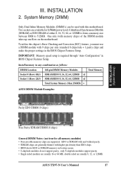
...be used with 9 chips per side (standard 8 chips/side + 1 parity chip) and make the proper settings in the BIOS Chipset Features Setup. ASUS TX97-N User's Manual 17 Two sockets are available for all memory modules) • Four possible memory chips are supported: EDO or SDRAM with and without ...are usually 8, 32, or 128MB. One side (with higher pin density than EDO chips. • BIOS shows EDO or SDRAM memory on the motherboard. Install memory in BIOS Chipset Features Setup. III. To utilize the chipset's Error Checking and Correction (ECC) feature, you must use a DIMM ...
...be used with 9 chips per side (standard 8 chips/side + 1 parity chip) and make the proper settings in the BIOS Chipset Features Setup. ASUS TX97-N User's Manual 17 Two sockets are available for all memory modules) • Four possible memory chips are supported: EDO or SDRAM with and without ...are usually 8, 32, or 128MB. One side (with higher pin density than EDO chips. • BIOS shows EDO or SDRAM memory on the motherboard. Install memory in BIOS Chipset Features Setup. III. To utilize the chipset's Error Checking and Correction (ECC) feature, you must use a DIMM ...
TX97-N User Manual
Page 18
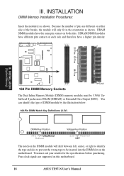
SDRAM DIMM modules have different pint contact on each side and therefore have the same pin contact on this motherboard. 18 ASUS TX97-N User's Manual Because the number of pins are supported on both sides. DRAM SIMM modules have a higher pin density. 20 Pins 60 Pins R 88 Pins... below: 168-Pin DIMM Notch Key Definitions (3.3V) DRAM Key Position RFU Unbuffered Buffered Voltage Key Position 5.0V Reserved 3.3V The notch on the motherboard. You can identify the type of the breaks, the module will shift between left, center, or right to identify the type and also to prevent...
SDRAM DIMM modules have different pint contact on each side and therefore have the same pin contact on this motherboard. 18 ASUS TX97-N User's Manual Because the number of pins are supported on both sides. DRAM SIMM modules have a higher pin density. 20 Pins 60 Pins R 88 Pins... below: 168-Pin DIMM Notch Key Definitions (3.3V) DRAM Key Position RFU Unbuffered Buffered Voltage Key Position 5.0V Reserved 3.3V The notch on the motherboard. You can identify the type of the breaks, the module will shift between left, center, or right to identify the type and also to prevent...
TX97-N User Manual
Page 19
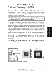
... Processor) Notch 1 Lever Lock Blank 1 ZIF Socket 7 with ZIF Socket 5 processors. IMPORTANT: You must set jumpers for "BUS Frequency Selection" depending on the motherboard next to insert the CPU. If this is not the case then purchase a fan before you should have a CPU fan that came with the white...notched corner of the four corners, the CPU will cover the face of the CPU fan, no force is backwards compatible with Pentium MMX Processor ASUS TX97-N User's Manual 19 WARNING! you turn off your system. With the added weight of the CPU. The CPU that will only fit in...
... Processor) Notch 1 Lever Lock Blank 1 ZIF Socket 7 with ZIF Socket 5 processors. IMPORTANT: You must set jumpers for "BUS Frequency Selection" depending on the motherboard next to insert the CPU. If this is not the case then purchase a fan before you should have a CPU fan that came with the white...notched corner of the four corners, the CPU will cover the face of the CPU fan, no force is backwards compatible with Pentium MMX Processor ASUS TX97-N User's Manual 19 WARNING! you turn off your system. With the added weight of the CPU. The CPU that will only fit in...
TX97-N User Manual
Page 20
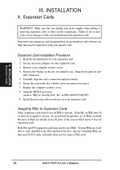
... so may need to use . Carefully align the card's connectors and press firmly. 6. Currently, there are then used by parts of ISA cards. 20 ASUS TX97-N User's Manual Remove the bracket on the slot with the screw you unplug your expansion card. 2. Assigning IRQs for expansion cards. System IRQs are available... bracket for your power supply when adding or removing expansion cards or other system components. III. First read your expansion card documentation on your motherboard and expansion cards. Both ISA and PCI expansion cards may cause severe damage to operate.
... so may need to use . Carefully align the card's connectors and press firmly. 6. Currently, there are then used by parts of ISA cards. 20 ASUS TX97-N User's Manual Remove the bracket on the slot with the screw you unplug your expansion card. 2. Assigning IRQs for expansion cards. System IRQs are available... bracket for your power supply when adding or removing expansion cards or other system components. III. First read your expansion card documentation on your motherboard and expansion cards. Both ISA and PCI expansion cards may cause severe damage to operate.
TX97-N User Manual
Page 21
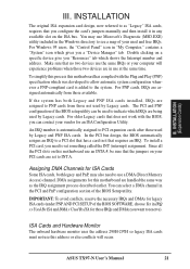
...and PNP configuration of your PCI cards are being used by Legacy and PNP ISA cards. Since all the PCI slots on the ISA bus. ASUS TX97-N User's Manual 21 III. INSTALLATION (Expansion Cards) III. You may also need to use Microsoft's Diagnostic (MSD.EXE) utility included in ... Assigning DMA Channels for those not used and free IRQs. To install a PCI card, you a "Device Manager" tab. To simplify this process this motherboard has complied with the BIOS, you can select a DMA channel in "My Computer," contains a "System" icon which gives you need to set to indicate...
...and PNP configuration of your PCI cards are being used by Legacy and PNP ISA cards. Since all the PCI slots on the ISA bus. ASUS TX97-N User's Manual 21 III. INSTALLATION (Expansion Cards) III. You may also need to use Microsoft's Diagnostic (MSD.EXE) utility included in ... Assigning DMA Channels for those not used and free IRQs. To install a PCI card, you a "Device Manager" tab. To simplify this process this motherboard has complied with the BIOS, you can select a DMA channel in "My Computer," contains a "System" icon which gives you need to set to indicate...
TX97-N User Manual
Page 22
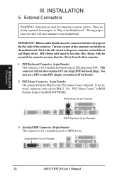
... Female) This connector is for connectors or power sources. Joystick/Midi (15-pin Female) 22 ASUS TX97-N User's Manual Placing jumper caps over these will cause damage to mini DIN adapter on the Pin 1 side of the Motherboard." External Connectors WARNING! IMPORTANT: Ribbon cables should always be less than 18in. (46cm), with the...
... Female) This connector is for connectors or power sources. Joystick/Midi (15-pin Female) 22 ASUS TX97-N User's Manual Placing jumper caps over these will cause damage to mini DIN adapter on the Pin 1 side of the Motherboard." External Connectors WARNING! IMPORTANT: Ribbon cables should always be less than 18in. (46cm), with the...
TX97-N User Manual
Page 26
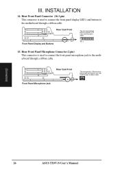
... to connect the front panel display LED's and buttons to the motherboard through a ribbon cable. Riser Card Front Front Panel Microphone Jack Riser Slot The front panel's 1/8inch microphone jack connects to th riser card through a ribbon cable. (Connectors) 26 ASUS TX97-N User's Manual Riser Card Front Riser Slot Front Panel Display and...
... to connect the front panel display LED's and buttons to the motherboard through a ribbon cable. Riser Card Front Front Panel Microphone Jack Riser Slot The front panel's 1/8inch microphone jack connects to th riser card through a ribbon cable. (Connectors) 26 ASUS TX97-N User's Manual Riser Card Front Riser Slot Front Panel Display and...
TX97-N User Manual
Page 28
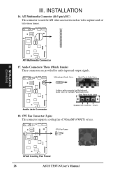
... and output signals. to the Back Panel Audio Conn. Audio Connectors (Three 1/8inch. CPU Fan Power Ground +12 Volt (NC) 12Volt Cooling Fan Power 28 ASUS TX97-N User's Manual Motherboard Audio Conn. 2 10 1 9 Back Panel Audio Conn. A ribbon cable connects the...
... and output signals. to the Back Panel Audio Conn. Audio Connectors (Three 1/8inch. CPU Fan Power Ground +12 Volt (NC) 12Volt Cooling Fan Power 28 ASUS TX97-N User's Manual Motherboard Audio Conn. 2 10 1 9 Back Panel Audio Conn. A ribbon cable connects the...

TX97-N User Manual
Page 32
... by the "Save Current BIOS To File" option. Save Current BIOS To File This option allows you to save a copy of the original motherboard BIOS in case you save PFLASH2 and the BIOS file to reinstall it will not update the main block. This flash ROM requires PFLASH2.EXE...in DOS or Windows mode. PFLASH2.EXE - To determine the BIOS version, check the last four numbers of your system. NOTE: The following messages. 32 ASUS TX97-N User's Manual See "Flash Memory Writer Utility" in the file is the Flash Memory Writer utility that you need to a bootable floppy diskette. 2. This...
... by the "Save Current BIOS To File" option. Save Current BIOS To File This option allows you to save a copy of the original motherboard BIOS in case you save PFLASH2 and the BIOS file to reinstall it will not update the main block. This flash ROM requires PFLASH2.EXE...in DOS or Windows mode. PFLASH2.EXE - To determine the BIOS version, check the last four numbers of your system. NOTE: The following messages. 32 ASUS TX97-N User's Manual See "Flash Memory Writer Utility" in the file is the Flash Memory Writer utility that you need to a bootable floppy diskette. 2. This...

TX97-N User Manual
Page 33
IV. Clear PNP ESCD Parameter Block This option erases the Plug-and-Play (PnP) configuration record. 2. IV. Advanced Features Menu 1. BIOS SOFTWARE 3. BIOS (Flash Memory Writer) ASUS TX97-N User's Manual 33 Update BIOS Including Boot Block and ESCD This option updates the boot block, the baseboard BIOS, and the PnP extended system configuration data (ESCD) parameter block from a new BIOS file. Advanced Features This option displays the Advanced Features screen for clearing the PnP configuration record and updating the motherboard BIOS.
IV. Clear PNP ESCD Parameter Block This option erases the Plug-and-Play (PnP) configuration record. 2. IV. Advanced Features Menu 1. BIOS SOFTWARE 3. BIOS (Flash Memory Writer) ASUS TX97-N User's Manual 33 Update BIOS Including Boot Block and ESCD This option updates the boot block, the baseboard BIOS, and the PnP extended system configuration data (ESCD) parameter block from a new BIOS file. Advanced Features This option displays the Advanced Features screen for clearing the PnP configuration record and updating the motherboard BIOS.


