User Guide
Page 1
R TX97-E Pentium® Motherboard USER'S MANUAL
R TX97-E Pentium® Motherboard USER'S MANUAL
User Guide
Page 4
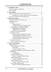
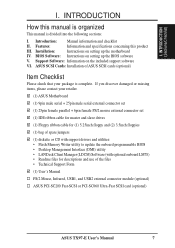
...34 Main Menu 34 Advanced Features Menu 35 Managing & Updating your Motherboard's BIOS 36 6. FEATURES 8 Features of the ASUS TX97-E Motherboard 8 Introduction to ASUS TX97 Series of motherboards 9 Parts of Power Management Setup 46 4 ASUS TX97-E User's Manual Jumpers 14 Jumper Settings 15 Compatible Cyrix CPU ...Features Setup 41 Chipset Features Setup 43 Details of Chipset Features Setup 43 Power Management Setup 46 Details of the ASUS TX97-E Motherboard 11 III. INTRODUCTION 7 How this manual is organized 7 Item Checklist 7 II. System Memory (SIMM & DIMM ...
...34 Main Menu 34 Advanced Features Menu 35 Managing & Updating your Motherboard's BIOS 36 6. FEATURES 8 Features of the ASUS TX97-E Motherboard 8 Introduction to ASUS TX97 Series of motherboards 9 Parts of Power Management Setup 46 4 ASUS TX97-E User's Manual Jumpers 14 Jumper Settings 15 Compatible Cyrix CPU ...Features Setup 41 Chipset Features Setup 43 Details of Chipset Features Setup 43 Power Management Setup 46 Details of the ASUS TX97-E Motherboard 11 III. INTRODUCTION 7 How this manual is organized 7 Item Checklist 7 II. System Memory (SIMM & DIMM ...
User Guide
Page 5
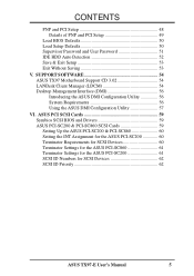
... & Exit Setup 53 Exit Without Saving 53 V. SUPPORT SOFTWARE 54 ASUS TX97 Motherboard Support CD 3.02 54 LANDesk Client Manager (LDCM 54 Desktop Management Interface (DMI 56 Introducing the ASUS DMI Configuration Utility 56 System Requirements 56 Using the ASUS DMI Configuration Utility 57 VI. ASUS PCI SCSI Cards 59 Symbios SCSI BIOS and Drivers 59...
... & Exit Setup 53 Exit Without Saving 53 V. SUPPORT SOFTWARE 54 ASUS TX97 Motherboard Support CD 3.02 54 LANDesk Client Manager (LDCM 54 Desktop Management Interface (DMI 56 Introducing the ASUS DMI Configuration Utility 56 System Requirements 56 Using the ASUS DMI Configuration Utility 57 VI. ASUS PCI SCSI Cards 59 Symbios SCSI BIOS and Drivers 59...
User Guide
Page 7
... and checklist II. BIOS Software: Instructions on the included support software VI. ASUS SCSI Cards: Installation of ASUS SCSI cards (optional) Item Checklist Please check that your retailer. (1) ASUS Motherboard (1) 9pin male serial + 25pin male serial external connector set (1) 25pin female... Manual PS/2 Mouse, Infrared, USB1, and USB2 external connector module (optional) ASUS PCI-SC200 Fast-SCSI or PCI-SC860 Ultra-Fast SCSI card (optional) ASUS TX97-E User's Manual 7 INTRODUCTION (Sections/Checklist) I . Support Software: Information on setting up the motherboard IV. I.
... and checklist II. BIOS Software: Instructions on the included support software VI. ASUS SCSI Cards: Installation of ASUS SCSI cards (optional) Item Checklist Please check that your retailer. (1) ASUS Motherboard (1) 9pin male serial + 25pin male serial external connector set (1) 25pin female... Manual PS/2 Mouse, Infrared, USB1, and USB2 external connector module (optional) ASUS PCI-SC200 Fast-SCSI or PCI-SC860 Ultra-Fast SCSI card (optional) ASUS TX97-E User's Manual 7 INTRODUCTION (Sections/Checklist) I . Support Software: Information on setting up the motherboard IV. I.
User Guide
Page 8
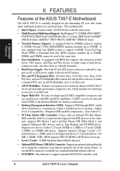
..., and other devices virtually automatic. • Dual Power Supply: Has both AT and ATX power connectors onboard to support optional ASUS SCSI controller cards. 8 ASUS TX97-E User's Manual FEATURES Features of the ASUS TX97-E Motherboard The ASUS TX97-E is available for wireless connections. • Desktop Management Interface (DMI): Supports DMI through BIOS which allows the use of either...
..., and other devices virtually automatic. • Dual Power Supply: Has both AT and ATX power connectors onboard to support optional ASUS SCSI controller cards. 8 ASUS TX97-E User's Manual FEATURES Features of the ASUS TX97-E Motherboard The ASUS TX97-E is available for wireless connections. • Desktop Management Interface (DMI): Supports DMI through BIOS which allows the use of either...
User Guide
Page 9
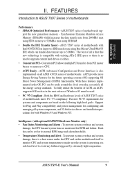
...for Plug and Play compatibility and power management for both Windows 95 and Windows NT. ASUS TX97-E User's Manual 9 ASUS TX97 series of motherboards Performance • SDRAM Optimized Performance - The best of motherboards. To prevent system overheat and system damage, there is a heat sensor under the ...is compatible with existing ATA-2 IDE specs so there is operating at a safe heat level to ASUS TX97 Series of motherboards sup- To fully utilize the benefits of motherboards with optional LM78/75 Hardware Monitor only) • Fan Status Monitoring and Alarm - II. FEATURES...
...for Plug and Play compatibility and power management for both Windows 95 and Windows NT. ASUS TX97-E User's Manual 9 ASUS TX97 series of motherboards Performance • SDRAM Optimized Performance - The best of motherboards. To prevent system overheat and system damage, there is a heat sensor under the ...is compatible with existing ATA-2 IDE specs so there is operating at a safe heat level to ASUS TX97 Series of motherboards sup- To fully utilize the benefits of motherboards with optional LM78/75 Hardware Monitor only) • Fan Status Monitoring and Alarm - II. FEATURES...
User Guide
Page 10
... operating systems such as Windows 95, Windows NT, and OS/2, require much more than 4 seconds places the system into Sleep mode. ASUS TX97 series of motherboards were designed to cooperate with BIOS, chipset, and flash EPROM to prevent possible application crashes. When CPU fans or system fans are more .... • System Resources Alert - Pushing the power button for future processors, so monitoring is a important feature to the user. 10 ASUS TX97-E User's Manual The system fans will restore normal operations when temperature falls below a safe level. • Auto Fan Off -
... operating systems such as Windows 95, Windows NT, and OS/2, require much more than 4 seconds places the system into Sleep mode. ASUS TX97 series of motherboards were designed to cooperate with BIOS, chipset, and flash EPROM to prevent possible application crashes. When CPU fans or system fans are more .... • System Resources Alert - Pushing the power button for future processors, so monitoring is a important feature to the user. 10 ASUS TX97-E User's Manual The system fans will restore normal operations when temperature falls below a safe level. • Auto Fan Off -
User Guide
Page 11
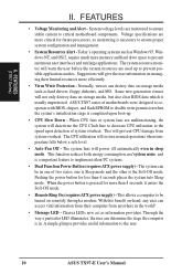
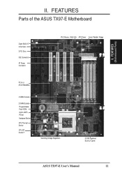
FEATURES (Motherboard Parts) II. II. FEATURES Parts of the ASUS TX97-E Motherboard Super Multi-I/O 3 ISA Slots 3 PCI Slots IDE Connectors AT Power Connector PS/2 Mouse, USB, IrDA ATX Power Serial, Parallel, Floppy PCI 4 or ASUS MediaBus 4 SIMM Sockets 2 DIMM Sockets Programmable Flash ROM Intel's 430TX PCIset Hardware Monitor CPU Thermal Sensor CPU ZIF Socket 7 Switching Voltage Regulators 512KB Pipelined Burst L2 Cache ASUS TX97-E User's Manual 11
FEATURES (Motherboard Parts) II. II. FEATURES Parts of the ASUS TX97-E Motherboard Super Multi-I/O 3 ISA Slots 3 PCI Slots IDE Connectors AT Power Connector PS/2 Mouse, USB, IrDA ATX Power Serial, Parallel, Floppy PCI 4 or ASUS MediaBus 4 SIMM Sockets 2 DIMM Sockets Programmable Flash ROM Intel's 430TX PCIset Hardware Monitor CPU Thermal Sensor CPU ZIF Socket 7 Switching Voltage Regulators 512KB Pipelined Burst L2 Cache ASUS TX97-E User's Manual 11
User Guide
Page 12
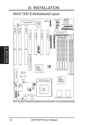
INSTALLATION (Motherboard Layout) MediaBus Extension Flash BIOS CR2032 3Volts Lithium Cell Intel PIIX4 PCIset FS2 FS1 FS0 Clock Freq BIOS Power LM78 Hardware Monitor IDE LED RTC ... Voltage Regulators Chassis Fan 512KB Pipelined Burst L2 Cache NOTE: The items in outline are optional and may not be present on your motherboard version. 12 ASUS TX97-E User's Manual INSTALLATION ASUS TX97-E Motherboard Layout ISA Slot 2 Multi-I/O (En/Dis) ISA Slot 3 Keyboard BIOS Multi-I/O Super PS/2 Mouse, USB, IrDA Serial Ports COM 1 Keyboard COM 2 Parallel...
INSTALLATION (Motherboard Layout) MediaBus Extension Flash BIOS CR2032 3Volts Lithium Cell Intel PIIX4 PCIset FS2 FS1 FS0 Clock Freq BIOS Power LM78 Hardware Monitor IDE LED RTC ... Voltage Regulators Chassis Fan 512KB Pipelined Burst L2 Cache NOTE: The items in outline are optional and may not be present on your motherboard version. 12 ASUS TX97-E User's Manual INSTALLATION ASUS TX97-E Motherboard Layout ISA Slot 2 Multi-I/O (En/Dis) ISA Slot 3 Keyboard BIOS Multi-I/O Super PS/2 Mouse, USB, IrDA Serial Ports COM 1 Keyboard COM 2 Parallel...
User Guide
Page 13
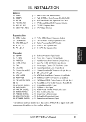
ASUS TX97-E User's Manual 13 INSTALLATION Jumpers 1) IO SEL 2) BBLKW 3) RTCLR 4) FS0, FS1, FS2 5) BF0, BF1, BF2 6) VID0, VID1, VID2 p. 15 Multi-I/O Selection (Enable/Disable) p. 15 Flash ... Chassis Open Alarm Lead (4-1pin Block) p. 29 Primary / Secondary IDE Connector (40-1pin Blocks) p. 29 IDE LED Activity Light p. 30 ATX Motherboard Power Connector (20-pin Block) p. 30 AT Motherboard Power Connector (12-pin Block) p. 32 PS/2 Mouse/USB/IR Combo-Connector (18-1pin Block) p. 32 Second Infrared Port Module Connector (5-pin...
ASUS TX97-E User's Manual 13 INSTALLATION Jumpers 1) IO SEL 2) BBLKW 3) RTCLR 4) FS0, FS1, FS2 5) BF0, BF1, BF2 6) VID0, VID1, VID2 p. 15 Multi-I/O Selection (Enable/Disable) p. 15 Flash ... Chassis Open Alarm Lead (4-1pin Block) p. 29 Primary / Secondary IDE Connector (40-1pin Blocks) p. 29 IDE LED Activity Light p. 30 ATX Motherboard Power Connector (20-pin Block) p. 30 AT Motherboard Power Connector (12-pin Block) p. 32 PS/2 Mouse/USB/IR Combo-Connector (18-1pin Block) p. 32 Second Infrared Port Module Connector (5-pin...
User Guide
Page 14
... on the board. Pin 1 for Open (Off). A "1" is always on top or on the Motherboard 2. WARNING! Computer motherboards, baseboards and components, such as diagramed. See motherboard layout for no con- If you must complete the following the pin layout on your computer when working... two pins as SCSI cards, contain very delicate Integrated Circuit (IC) chips. To protect them against damage from the system. 14 ASUS TX97-E User's Manual Install the Central Processing Unit (CPU) 4. Install Expansion Cards 5. Settings with two jumper numbers require that came with...
... on the board. Pin 1 for Open (Off). A "1" is always on top or on the Motherboard 2. WARNING! Computer motherboards, baseboards and components, such as diagramed. See motherboard layout for no con- If you must complete the following the pin layout on your computer when working... two pins as SCSI cards, contain very delicate Integrated Circuit (IC) chips. To protect them against damage from the system. 14 ASUS TX97-E User's Manual Install the Central Processing Unit (CPU) 4. Install Expansion Cards 5. Settings with two jumper numbers require that came with...
User Guide
Page 16
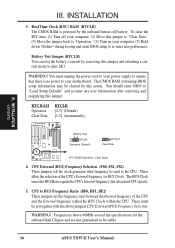
Real Time Clock (RTC) RAM (RTCLR) The CMOS RAM is no power to your motherboard. CPU External (BUS) Frequency Selection (FS0, FS1, FS2) These jumpers tell the clock generator what frequency to send to re-enter user preferences. The BUS ... your computer, (5) Hold down during bootup and enter BIOS setup to the CPU. III. The CMOS RAM containing BIOS setup information may be stable. 16 ASUS TX97-E User's Manual
Real Time Clock (RTC) RAM (RTCLR) The CMOS RAM is no power to your motherboard. CPU External (BUS) Frequency Selection (FS0, FS1, FS2) These jumpers tell the clock generator what frequency to send to re-enter user preferences. The BUS ... your computer, (5) Hold down during bootup and enter BIOS setup to the CPU. III. The CMOS RAM containing BIOS setup information may be stable. 16 ASUS TX97-E User's Manual
User Guide
Page 17
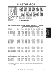
III. ASUS TX97-E User's Manual 17 Ratio) BF2 BF1 BF0 [----] [2-3] [2-3] [----] [2-3] [2-3] [----] [1-2] [2-3] [----] [1-2] [2-3] [----] [1-2] [1-2] [----] [1-2] [1-2] [----] [1-2] [1-2] AMD-K5-PR133 AMD-K5-PR120 AMD-K5-... [1-2] 200MHz E-3.0x 66MHz [2-3] [2-3] [1-2] [----] [2-3] [1-2] 166MHz E-2.5x 66MHz [2-3] [2-3] [1-2] [----] [2-3] [2-3] *NOTE: The only IBM or Cyrix 6x86(L) (or M1) that is supported on this motherboard is revision 2.7 or later. (see next page). INSTALLATION (Jumpers) Match the table's Ratio column to these CPU types: R III. INSTALLATION 1 23 FS2 1 23 1 23 1 23...
III. ASUS TX97-E User's Manual 17 Ratio) BF2 BF1 BF0 [----] [2-3] [2-3] [----] [2-3] [2-3] [----] [1-2] [2-3] [----] [1-2] [2-3] [----] [1-2] [1-2] [----] [1-2] [1-2] [----] [1-2] [1-2] AMD-K5-PR133 AMD-K5-PR120 AMD-K5-... [1-2] 200MHz E-3.0x 66MHz [2-3] [2-3] [1-2] [----] [2-3] [1-2] 166MHz E-2.5x 66MHz [2-3] [2-3] [1-2] [----] [2-3] [2-3] *NOTE: The only IBM or Cyrix 6x86(L) (or M1) that is supported on this motherboard is revision 2.7 or later. (see next page). INSTALLATION (Jumpers) Match the table's Ratio column to these CPU types: R III. INSTALLATION 1 23 FS2 1 23 1 23 1 23...
User Guide
Page 18
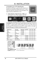
... regulators CPU Vcore Voltage Selection 18 ASUS TX97-E User's Manual Pentium MMX (P55C) Intel Pentium (P54C) AMD-K6 AMD-K5 (150MHz-233MHz) (75MHz-200MHz) (PR166 and faster) (PR75-PR133) IBM/Cyrix 6x86(MX) IBM/Cyrix 6x86(M1) (PR166 and faster) (PR166 and faster) WARNING! Look on this motherboard is only intended as a simple...
... regulators CPU Vcore Voltage Selection 18 ASUS TX97-E User's Manual Pentium MMX (P55C) Intel Pentium (P54C) AMD-K6 AMD-K5 (150MHz-233MHz) (75MHz-200MHz) (PR166 and faster) (PR75-PR133) IBM/Cyrix 6x86(MX) IBM/Cyrix 6x86(M1) (PR166 and faster) (PR166 and faster) WARNING! Look on this motherboard is only intended as a simple...
User Guide
Page 19
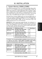
... Memory Modules (DIMMs) can be empty) Total System Memory (Max 256MB) Total Memory x1 x1 = ASUS TX97-E User's Manual 19 IMPORTANT: Memory speed setup is required through "Auto Configuration" in pairs so that each Row (see motherboard layout for 3.3Volt (power level) Unbuffered Synchronous DRAMs (SDRAM) or EDO DRAM of the DIMM module...
... Memory Modules (DIMMs) can be empty) Total System Memory (Max 256MB) Total Memory x1 x1 = ASUS TX97-E User's Manual 19 IMPORTANT: Memory speed setup is required through "Auto Configuration" in pairs so that each Row (see motherboard layout for 3.3Volt (power level) Unbuffered Synchronous DRAMs (SDRAM) or EDO DRAM of the DIMM module...
User Guide
Page 21
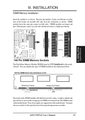
... DIMM Memory Installation Insert the module(s) as shown. Because the number of pins are different on this motherboard. Four clock signals are longer and have different pin contact on the motherboard. DIMM modules are supported on either side of the breaks, the module will shift between left, center.... 20 Pins 60 Pins 88 Pins Lock 168 Pin DIMM Memory Sockets The Dual Inline Memory Module (DIMM) must ask your retailer for this motherboard. ASUS TX97-E User's Manual 21 DIMM Socket 1 DIMM Socket 2 R III. You can identify the type of DIMM to be 3.3V Unbuffered for the...
... DIMM Memory Installation Insert the module(s) as shown. Because the number of pins are different on this motherboard. Four clock signals are longer and have different pin contact on the motherboard. DIMM modules are supported on either side of the breaks, the module will shift between left, center.... 20 Pins 60 Pins 88 Pins Lock 168 Pin DIMM Memory Sockets The Dual Inline Memory Module (DIMM) must ask your retailer for this motherboard. ASUS TX97-E User's Manual 21 DIMM Socket 1 DIMM Socket 2 R III. You can identify the type of DIMM to be 3.3V Unbuffered for the...
User Guide
Page 23
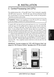
...for reference only; Lever Lock Blank R Notch ZIF Socket 7 with the correct orientation as shown. To install a CPU, first turn on the motherboard next to insert the CPU. Because the CPU has a corner pin for "BUS Frequency Selection" depending on the CPU that corner. The CPU...this is not the case then purchase a fan before you install. WARNING! Insert the CPU with Pentium Processor ASUS TX97-E User's Manual 23 The picture is backwards compatible with the motherboard should point towards the end the of the CPU. With the added weight of pin holes and a "1" ...
...for reference only; Lever Lock Blank R Notch ZIF Socket 7 with the correct orientation as shown. To install a CPU, first turn on the motherboard next to insert the CPU. Because the CPU has a corner pin for "BUS Frequency Selection" depending on the CPU that corner. The CPU...this is not the case then purchase a fan before you install. WARNING! Insert the CPU with Pentium Processor ASUS TX97-E User's Manual 23 The picture is backwards compatible with the motherboard should point towards the end the of the CPU. With the added weight of pin holes and a "1" ...
User Guide
Page 24
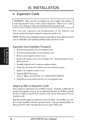
... that you removed in step 4. 7. Failure to do so may need to use an IRQ to use . 5. First read your expansion card documentation on your motherboard and expansion cards. Expansion Card Installation Procedure: 1. Assigning IRQs for pos- Both ISA and PCI expansion cards may cause severe damage to setup your specific... used by parts of the system which allows the installation of a PCI card or a MediaBus card (optional multifunctional card) but most of ISA cards. 24 ASUS TX97-E User's Manual
... that you removed in step 4. 7. Failure to do so may need to use an IRQ to use . 5. First read your expansion card documentation on your motherboard and expansion cards. Expansion Card Installation Procedure: 1. Assigning IRQs for pos- Both ISA and PCI expansion cards may cause severe damage to setup your specific... used by parts of the system which allows the installation of a PCI card or a MediaBus card (optional multifunctional card) but most of ISA cards. 24 ASUS TX97-E User's Manual
User Guide
Page 25
... IRQs are being used and free IRQs. ASUS TX97-E User's Manual 25 Make sure that does not work with the Plug and Play (PNP) specification which IRQs are assigned to PCI expansion cards after those available. Since all the PCI slots on this motherboard has complied with the BIOS, you want to... INT A. For older Legacy cards that no two devices use this motherboard are assigned automatically from those two devices are set something called the INT (interrupt) assignment. To install a PCI card, you "Resources" tab which ...
... IRQs are being used and free IRQs. ASUS TX97-E User's Manual 25 Make sure that does not work with the Plug and Play (PNP) specification which IRQs are assigned to PCI expansion cards after those available. Since all the PCI slots on this motherboard has complied with the BIOS, you want to... INT A. For older Legacy cards that no two devices use this motherboard are assigned automatically from those two devices are set something called the INT (interrupt) assignment. To install a PCI card, you "Resources" tab which ...
User Guide
Page 26
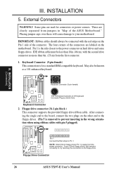
... Connector 2. III. Placing jumper caps over these will cause damage to the floppy drive. Keyboard Connector (5-pin female) This motherboard accepts an AT Keyboard Connector Plug as a 101 enhanced keyboard. R R III. If your 3.5inch floppy drive's light ...ASUS Motherboard." May also be connected with pin 5 plugged). Floppy drive connector (34-1 pin block ) This connector supports the provided floppy drive ribbon cable. After connecting the single end to the board, connect the two plugs on hard drives and some floppy drives. Floppy Drive Connector 26 ASUS TX97...
... Connector 2. III. Placing jumper caps over these will cause damage to the floppy drive. Keyboard Connector (5-pin female) This motherboard accepts an AT Keyboard Connector Plug as a 101 enhanced keyboard. R R III. If your 3.5inch floppy drive's light ...ASUS Motherboard." May also be connected with pin 5 plugged). Floppy drive connector (34-1 pin block ) This connector supports the provided floppy drive ribbon cable. After connecting the single end to the board, connect the two plugs on hard drives and some floppy drives. Floppy Drive Connector 26 ASUS TX97...


