
Service Guide
Page 3
... 1-3 1.2 System specifications 1-4 1.3 Front panel features 1-5 1.4 Rear panel features 1-6 1.5 Internal features 1-7 1.6 LED information 1-8 Chapter 2: Hardware setup 2.1 Chassis cover 2-2 2.1.1 Removing the side cover 2-2 2.1.2 Reinstalling the side cover 2-3 2.2 Motherboard information 2-4 2.3 Central Processing Unit (CPU 2-5 2.3.1 Overview 2-5 2.3.2 Installing the CPU 2-5 2.3.3 Installing the heatsink and fan 2-7 2.4 System memory 2-9 2.4.1 Overview 2-9 2.4.2 Memory Configurations 2-10 2.4.3 Installing a DIMM 2-11 2.4.4 Removing a DIMM...
... 1-3 1.2 System specifications 1-4 1.3 Front panel features 1-5 1.4 Rear panel features 1-6 1.5 Internal features 1-7 1.6 LED information 1-8 Chapter 2: Hardware setup 2.1 Chassis cover 2-2 2.1.1 Removing the side cover 2-2 2.1.2 Reinstalling the side cover 2-3 2.2 Motherboard information 2-4 2.3 Central Processing Unit (CPU 2-5 2.3.1 Overview 2-5 2.3.2 Installing the CPU 2-5 2.3.3 Installing the heatsink and fan 2-7 2.4 System memory 2-9 2.4.1 Overview 2-9 2.4.2 Memory Configurations 2-10 2.4.3 Installing a DIMM 2-11 2.4.4 Removing a DIMM...

Service Guide
Page 4
... the footpads or roller wheels 3-2 Removing the top cover 3-2 Attaching the rack rails 3-2 Chapter 4: Motherboard info 4.1 Motherboard layout 4-2 4.2 Jumpers 4-4 4.3 Internal connectors 4-7 Chapter 5: BIOS information 5.1 Managing and updating your BIOS... 5-2 5.1.1 Creating a bootable floppy disk 5-2 5.1.2 Updating the BIOS 5-3 5.1.3 Saving the current BIOS file 5-5 5.1.4 ASUS CrashFree BIOS 2 utility 5-6 5.1.5 ASUS EZ Flash utility 5-8 5.1.6 ASUS...
... the footpads or roller wheels 3-2 Removing the top cover 3-2 Attaching the rack rails 3-2 Chapter 4: Motherboard info 4.1 Motherboard layout 4-2 4.2 Jumpers 4-4 4.3 Internal connectors 4-7 Chapter 5: BIOS information 5.1 Managing and updating your BIOS... 5-2 5.1.1 Creating a bootable floppy disk 5-2 5.1.2 Updating the BIOS 5-3 5.1.3 Saving the current BIOS file 5-5 5.1.4 ASUS CrashFree BIOS 2 utility 5-6 5.1.5 ASUS EZ Flash utility 5-8 5.1.6 ASUS...
Service Guide
Page 9
... Introduction This chapter describes the general features of the BIOS parameters are also provided. 6. This chapter includes the motherboard layout, jumper settings, and connector locations. 5. Chapter 4: Motherboard information This chapter gives information about the motherboard that the barebone server supports. 7. About this guide Audience This user guide is intended for system integrators and...
... Introduction This chapter describes the general features of the BIOS parameters are also provided. 6. This chapter includes the motherboard layout, jumper settings, and connector locations. 5. Chapter 4: Motherboard information This chapter gives information about the motherboard that the barebone server supports. 7. About this guide Audience This user guide is intended for system integrators and...

Service Guide
Page 12
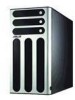
1.1 System package contents Check your system package for the following items. Chassis Motherboard Components Cables Accessories Application CDs ASUS AK25 5U rackmount chassis ASUS K8N-DL motherboard 600 W single power supply SATA backplane board Front I/O board 52x CD-ROM or DVD-ROM ... screws and cables Dummy covers System keys (2 pcs.) TW510-E2 support CD with ASWM* Computer Associates® eTrust™ anti-virus CD Documentation Optional items ASUS TW510-E2 user guide ASUS ASWM 2.0 user guide ASUS AK25 rackmount rail kit *ASUS System Web-based Management If any of the above items...
1.1 System package contents Check your system package for the following items. Chassis Motherboard Components Cables Accessories Application CDs ASUS AK25 5U rackmount chassis ASUS K8N-DL motherboard 600 W single power supply SATA backplane board Front I/O board 52x CD-ROM or DVD-ROM ... screws and cables Dummy covers System keys (2 pcs.) TW510-E2 support CD with ASWM* Computer Associates® eTrust™ anti-virus CD Documentation Optional items ASUS TW510-E2 user guide ASUS ASWM 2.0 user guide ASUS AK25 rackmount rail kit *ASUS System Web-based Management If any of the above items...
Service Guide
Page 13
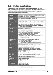
... slot 2 x PCI slots 1 x 3.25-inch FDD bay 3 x 5.25-inch drive bays (continued on this motherboard due to 12 GB on the next page) ASUS TW510-E2 1-3 1.2 System specifications The ASUS TW510-E2 is a barebone server system featuring the ASUS K8N-DL motherboard. Chassis System dimension Motherboard CPU Chipset Memory Storage and RAID LAN Audio IEEE 1394 USB Expansion slots Drive...
... slot 2 x PCI slots 1 x 3.25-inch FDD bay 3 x 5.25-inch drive bays (continued on this motherboard due to 12 GB on the next page) ASUS TW510-E2 1-3 1.2 System specifications The ASUS TW510-E2 is a barebone server system featuring the ASUS K8N-DL motherboard. Chassis System dimension Motherboard CPU Chipset Memory Storage and RAID LAN Audio IEEE 1394 USB Expansion slots Drive...

Service Guide
Page 14
... LAN (RJ-45) port 4 x USB 2.0 ports 1 x Optical S/PDIF out port 1 x Coaxial S/PDIF out port 1 x PS/2 keyboard port 1 x PS/2 mouse port 8-channel audio ports ASUS Server Web-based Management (ASWM) 2.0 Voltage, temperature, CPU and memory utilization, and fan speed monitoring Automatic Server Restart (ASR) feature Windows® 2000 Professional (Service... Pack 4) Windows® XP Professional (Service Pack 2) 600 W power supply (with 24-pin and 8-pin power plugs) Refer to "Chapter 4 Motherboard information" for details on the internal connectors. 1-4 Chapter 1: Product introduction
... LAN (RJ-45) port 4 x USB 2.0 ports 1 x Optical S/PDIF out port 1 x Coaxial S/PDIF out port 1 x PS/2 keyboard port 1 x PS/2 mouse port 8-channel audio ports ASUS Server Web-based Management (ASWM) 2.0 Voltage, temperature, CPU and memory utilization, and fan speed monitoring Automatic Server Restart (ASR) feature Windows® 2000 Professional (Service... Pack 4) Windows® XP Professional (Service Pack 2) 600 W power supply (with 24-pin and 8-pin power plugs) Refer to "Chapter 4 Motherboard information" for details on the internal connectors. 1-4 Chapter 1: Product introduction

Service Guide
Page 16
... e r c o n n e c t o r 12 cm system fan Chassis cover lock Chassis intrusion switch Expansion slots Rear panel I /O ports, expansion slots, a chassis lock and intrusion switch, a vent for the motherboard rear I /O ports PS/2 keyboard port Coaxial S/PDIF Out port Optical S/PDIF Out port Serial port USB ports Center/Subwoofer port Microphone port Line Out port...
... e r c o n n e c t o r 12 cm system fan Chassis cover lock Chassis intrusion switch Expansion slots Rear panel I /O ports, expansion slots, a chassis lock and intrusion switch, a vent for the motherboard rear I /O ports PS/2 keyboard port Coaxial S/PDIF Out port Optical S/PDIF Out port Serial port USB ports Center/Subwoofer port Microphone port Line Out port...

Service Guide
Page 17
Power supply cage 2. Chassis intrusion switch 5. Front I/O board 10. Expansion card locks 6. Optical drive 7. 2 x 5.25-inch drive bays 8. SATA backplane (hidden) ASUS TW510-E2 1-7 Hard disk drive cage 9. K8N-DL motherboard 4. HDD fan (inside) 11. 1.5 Internal features The barebone server system includes the basic components as shown. 6 1 7 2 3 4 5 11 10 8 9 1. Chassis fan 3.
Power supply cage 2. Chassis intrusion switch 5. Front I/O board 10. Expansion card locks 6. Optical drive 7. 2 x 5.25-inch drive bays 8. SATA backplane (hidden) ASUS TW510-E2 1-7 Hard disk drive cage 9. K8N-DL motherboard 4. HDD fan (inside) 11. 1.5 Internal features The barebone server system includes the basic components as shown. 6 1 7 2 3 4 5 11 10 8 9 1. Chassis fan 3.

Service Guide
Page 22
... chassis by ten (10) screws as indicated by the circles in the illustration below. 2.2 Motherboard information The barebone server comes with the K8N-DL motherboard already installed. Failure to unplug the power cord before installing or removing any motherboard component or connection. Place this side towards the rear of the chassis ® K8N...
... chassis by ten (10) screws as indicated by the circles in the illustration below. 2.2 Motherboard information The barebone server comes with the K8N-DL motherboard already installed. Failure to unplug the power cord before installing or removing any motherboard component or connection. Place this side towards the rear of the chassis ® K8N...

Service Guide
Page 23
... corner of the rear panel to section "2.10 Removable components" for the installation. ASUS TW510-E2 2-5 Before installing the CPU, remove the chassis fan attached to the inner side of the CPU socket. 2.3 Central Processing Unit (CPU) 2.3.1 Overview The motherboard comes with only 32-bit or 64-bit wide data paths. Take note of...
... corner of the rear panel to section "2.10 Removable components" for the installation. ASUS TW510-E2 2-5 Before installing the CPU, remove the chassis fan attached to the inner side of the CPU socket. 2.3 Central Processing Unit (CPU) 2.3.1 Overview The motherboard comes with only 32-bit or 64-bit wide data paths. Take note of...

Service Guide
Page 25
Your system comes with other motherboard components. • Make sure that the heatsink fits properly on the retention module base. Follow these CPU fans with two proprietary CPU fan and heatsink ... applied to install the CPU heatsink and fan. 1. ASUS TW510-E2 2-7 Attach one end of the installed CPU, making sure that a Thermal Interface Material is already installed on top of the retention bracket to ensure optimum thermal condition and performance. Place the heatsink on the motherboard upon purchase. • You do not have to...
Your system comes with other motherboard components. • Make sure that the heatsink fits properly on the retention module base. Follow these CPU fans with two proprietary CPU fan and heatsink ... applied to install the CPU heatsink and fan. 1. ASUS TW510-E2 2-7 Attach one end of the installed CPU, making sure that a Thermal Interface Material is already installed on top of the retention bracket to ensure optimum thermal condition and performance. Place the heatsink on the motherboard upon purchase. • You do not have to...

Service Guide
Page 27
The following figure illustrates the location of the sockets: DIMM_A3 DIMM_B3 DIMM_B2 80 Pins DIMM_A2 DIMM_B1 DIMM_A1 104 Pins ® K8N-DL K8N-DL 184-pin DDR DIMM sockets For CPU 1 Channel A Channel B For CPU 2 Channel A Channel B Sockets DIMM_A1 and DIMM_A2 DIMM_B1 and DIMM_B2 Sockets DIMM_A3 DIMM_B3 ASUS TW510-E2 2-9 2.4 System memory 2.4.1 Overview The motherboard comes with six 184-pin Double Data Rate (DDR) Dual Inline Memory Modules (DIMM) sockets.
The following figure illustrates the location of the sockets: DIMM_A3 DIMM_B3 DIMM_B2 80 Pins DIMM_A2 DIMM_B1 DIMM_A1 104 Pins ® K8N-DL K8N-DL 184-pin DDR DIMM sockets For CPU 1 Channel A Channel B For CPU 2 Channel A Channel B Sockets DIMM_A1 and DIMM_A2 DIMM_B1 and DIMM_B2 Sockets DIMM_A3 DIMM_B3 ASUS TW510-E2 2-9 2.4 System memory 2.4.1 Overview The motherboard comes with six 184-pin Double Data Rate (DDR) Dual Inline Memory Modules (DIMM) sockets.

Service Guide
Page 29
...outward to avoid damaging the DIMM. 3. DO NOT force a DIMM into the socket until the retaining clips snap back in only one direction. ASUS TW510-E2 2-11 Failure to do so may cause severe damage to remove a DIMM. 2 1. Align a DIMM on the socket such that it ... seated. Unlock a DIMM socket by pressing the retaining clips outward. 2. Locked retaining clip 2.4.4 Removing a DIMM Follow these steps to both the motherboard and the components. 1. 2.4.3 Installing a DIMM Make sure to unplug the power supply before adding or removing DIMMs or other system components. Remove...
...outward to avoid damaging the DIMM. 3. DO NOT force a DIMM into the socket until the retaining clips snap back in only one direction. ASUS TW510-E2 2-11 Failure to do so may cause severe damage to remove a DIMM. 2 1. Align a DIMM on the socket such that it ... seated. Unlock a DIMM socket by pressing the retaining clips outward. 2. Locked retaining clip 2.4.4 Removing a DIMM Follow these steps to both the motherboard and the components. 1. 2.4.3 Installing a DIMM Make sure to unplug the power supply before adding or removing DIMMs or other system components. Remove...

Service Guide
Page 32
... power cable before installing or removing any system components. Failure to do so may be connected to an AC power source, make sure to the motherboard and other system components!
... power cable before installing or removing any system components. Failure to do so may be connected to an AC power source, make sure to the motherboard and other system components!

Service Guide
Page 39
ASUS TW510-E2 2-21 Refer to the SATA connector at the back of the SATA connectors. Connect one end of the supplied 7-pin SATA cable to Chapter 4 for the location of the drive. 9. Connect the other end to a SATA connector on the motherboard. 8.
ASUS TW510-E2 2-21 Refer to the SATA connector at the back of the SATA connectors. Connect one end of the supplied 7-pin SATA cable to Chapter 4 for the location of the drive. 9. Connect the other end to a SATA connector on the motherboard. 8.
Service Guide
Page 43
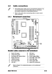
...remove pre-installed components to install additional devices. • Refer to this section when reconnecting cables to ensure correct cable connections. 2.9.1 Motherboard connections PS/2KBMS T: Mouse B: Keyboard SPDIF_O1 KBPWR1 SPDIF_O2 26.7cm (10.5in) 8 CPU_FAN2 ATX12V1 1 Super I/O 4 PARALLEL PORT ...on the motherboard connectors. Front USB cable 13. Chassis intrusion 6. Power supply SMBus 11. Serial ATA connectors Refer to the motherboard 14 1. 8-pin 12V power 2. 24-pin ATX power 3. CPU fan 1 8. Front IEEE 1394 cable 12. Front audio cable 14. ASUS TW510-E2 2-25 ...
...remove pre-installed components to install additional devices. • Refer to this section when reconnecting cables to ensure correct cable connections. 2.9.1 Motherboard connections PS/2KBMS T: Mouse B: Keyboard SPDIF_O1 KBPWR1 SPDIF_O2 26.7cm (10.5in) 8 CPU_FAN2 ATX12V1 1 Super I/O 4 PARALLEL PORT ...on the motherboard connectors. Front USB cable 13. Chassis intrusion 6. Power supply SMBus 11. Serial ATA connectors Refer to the motherboard 14 1. 8-pin 12V power 2. 24-pin ATX power 3. CPU fan 1 8. Front IEEE 1394 cable 12. Front audio cable 14. ASUS TW510-E2 2-25 ...

Service Guide
Page 45
... rear panel when installed. ASUS TW510-E2 J1 setting (1-3 shorted, 2-4 shorted) Device Drive Bay 1 Drive Bay 2 Drive Bay 3 Drive Bay 4 SATA BP ID CON2 CON4 CON6 CON8 2-27 Fan connector (for HDD fan) Power connectors (connect power plugs from the power supply) S M B u s c o n n e c t o r (upper 6-1 pins) (connects the SMB cable from the motherboard) P o w e r S M B u s c o n n e c t o r (lower 6-1 pins) (connects...
... rear panel when installed. ASUS TW510-E2 J1 setting (1-3 shorted, 2-4 shorted) Device Drive Bay 1 Drive Bay 2 Drive Bay 3 Drive Bay 4 SATA BP ID CON2 CON4 CON6 CON8 2-27 Fan connector (for HDD fan) Power connectors (connect power plugs from the power supply) S M B u s c o n n e c t o r (upper 6-1 pins) (connects the SMB cable from the motherboard) P o w e r S M B u s c o n n e c t o r (lower 6-1 pins) (connects...
Service Guide
Page 46
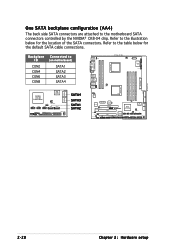
... connectors controlled by the NVIDIA® CK8-04 chip. One SATA backplane configuration (AA4) The back side SATA connectors are attached to (on motherboard) SATA1 SATA2 SATA3 SATA4 SATA3 SATA4 NVIDIA CK8-04 Professional 4Mb BIOS USB56 USB78 CLRTC1 FRNT_FAN1 USB910 SATA1 SATA2 BPSMB1 PRI_IDE1 TA_RAID4 RAID_EN1 CHASSIS1 FRNT_FAN2 ...
... connectors controlled by the NVIDIA® CK8-04 chip. One SATA backplane configuration (AA4) The back side SATA connectors are attached to (on motherboard) SATA1 SATA2 SATA3 SATA4 SATA3 SATA4 NVIDIA CK8-04 Professional 4Mb BIOS USB56 USB78 CLRTC1 FRNT_FAN1 USB910 SATA1 SATA2 BPSMB1 PRI_IDE1 TA_RAID4 RAID_EN1 CHASSIS1 FRNT_FAN2 ...

Service Guide
Page 47
... removing system devices, or when you need to remove the following components: 1. Disconnect the 3-pin fan cable from the center of the chassis. 3. Lock hooks ASUS TW510-E2 2-29 HDD blowers 3. Floppy disk drive module 5. This section tells how to replace defective components. Power supply 2.10.1 Chassis fan To remove the chassis fan... on the outer corners of the system fan, then pull the fan out of the case until it is detached. Press the tabs on the motherboard. 2. Chassis footpads and roller wheels 7. SATA backplane(s) 4. Front I/O board 6. Chassis fan 2.
... removing system devices, or when you need to remove the following components: 1. Disconnect the 3-pin fan cable from the center of the chassis. 3. Lock hooks ASUS TW510-E2 2-29 HDD blowers 3. Floppy disk drive module 5. This section tells how to replace defective components. Power supply 2.10.1 Chassis fan To remove the chassis fan... on the outer corners of the system fan, then pull the fan out of the case until it is detached. Press the tabs on the motherboard. 2. Chassis footpads and roller wheels 7. SATA backplane(s) 4. Front I/O board 6. Chassis fan 2.

Service Guide
Page 49
3. Due to slightly push it inward (toward the motherboard) before completely detaching the fan cage from the chassis. 3. To easily remove the fan cage, try to space constraints inside ... interfere with the removal of the chassis. Push the fan into the chassis until the four hooks lock securely into the holes on the motherboard. 2.10.2 HDD fan To remove the HDD fan: 1. Disconnect the 3-pin fan cable from the fan connector on the backplane before... it out of the fan cage. Re-connect the 3-pin fan cable from the connector REAR_FAN1 on the rear panel. 4. ASUS TW510-E2 2-31
3. Due to slightly push it inward (toward the motherboard) before completely detaching the fan cage from the chassis. 3. To easily remove the fan cage, try to space constraints inside ... interfere with the removal of the chassis. Push the fan into the chassis until the four hooks lock securely into the holes on the motherboard. 2.10.2 HDD fan To remove the HDD fan: 1. Disconnect the 3-pin fan cable from the fan connector on the backplane before... it out of the fan cage. Re-connect the 3-pin fan cable from the connector REAR_FAN1 on the rear panel. 4. ASUS TW510-E2 2-31


