User Manual
Page 3
... features 1-7 1.7 LED information 1-8 1.7.1 Front panel LEDs 1-8 1.7.2 LAN (RJ-45) LEDs 1-8 Chapter 2: Hardware setup 2.1 Chassis cover 2-2 2.1.1 Removing the left side cover 2-2 2.1.2 Removing the right side cover 2-3 2.2 Motherboard overview 2-4 2.3 Central Processing Unit (CPU 2-5 2.3.1 Installing the CPU 2-5 2.3.2 Installing the CPU heatsink 2-8 2.4 System memory 2-10 2.4.1 Overview 2-10 2.4.2 Memory configurations 2-11 2.4.3 Installing a DIMM 2-12 2.4.4 Removing a DIMM...
... features 1-7 1.7 LED information 1-8 1.7.1 Front panel LEDs 1-8 1.7.2 LAN (RJ-45) LEDs 1-8 Chapter 2: Hardware setup 2.1 Chassis cover 2-2 2.1.1 Removing the left side cover 2-2 2.1.2 Removing the right side cover 2-3 2.2 Motherboard overview 2-4 2.3 Central Processing Unit (CPU 2-5 2.3.1 Installing the CPU 2-5 2.3.2 Installing the CPU heatsink 2-8 2.4 System memory 2-10 2.4.1 Overview 2-10 2.4.2 Memory configurations 2-11 2.4.3 Installing a DIMM 2-12 2.4.4 Removing a DIMM...
User Manual
Page 4
... fan 2-23 2.8.3 Removing the SATA backplane 2-24 2.9 Connecting cables 2-26 Chapter 3: Motherboard info 3.1 Motherboard layouts 3-2 3.2 Jumpers 3-6 3.3 Connectors 3-8 3.3.1 Rear panel connectors 3-8 3.3.2 Internal connectors 3-11 Chapter 4: BIOS infomation 4.1 Managing and updating your BIOS 4-2 4.1.1 ASUS Update utility 4-2 4.1.2 Creating a bootable floppy disk 4-5 4.1.3 ASUS EZ Flash 2 utility 4-6 4.1.4 AFUDOS utility 4-7 4.1.5 ASUS CrashFree BIOS 3 utility 4-9 4.2 BIOS setup program 4-10 4.2.1 BIOS menu screen...
... fan 2-23 2.8.3 Removing the SATA backplane 2-24 2.9 Connecting cables 2-26 Chapter 3: Motherboard info 3.1 Motherboard layouts 3-2 3.2 Jumpers 3-6 3.3 Connectors 3-8 3.3.1 Rear panel connectors 3-8 3.3.2 Internal connectors 3-11 Chapter 4: BIOS infomation 4.1 Managing and updating your BIOS 4-2 4.1.1 ASUS Update utility 4-2 4.1.2 Creating a bootable floppy disk 4-5 4.1.3 ASUS EZ Flash 2 utility 4-6 4.1.4 AFUDOS utility 4-7 4.1.5 ASUS CrashFree BIOS 3 utility 4-9 4.2 BIOS setup program 4-10 4.2.1 BIOS menu screen...
User Manual
Page 10
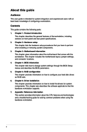
... and describes the BIOS parameters. 5. This chapter includes the motherboard layout, jumper settings, and connector locations. 4. Appendix: Reference information This section provides information about the motherboard that comes with at least basic knowledge of the workstation,... rear panel specifications. 2. Chapter 1: Product Introduction This chapter describes the general features of configuring a workstation. Chapter 3: Motherboard information This chapter gives information about the CPU features and technologies and a troubleshooting guide for solving common problems when using...
... and describes the BIOS parameters. 5. This chapter includes the motherboard layout, jumper settings, and connector locations. 4. Appendix: Reference information This section provides information about the motherboard that comes with at least basic knowledge of the workstation,... rear panel specifications. 2. Chapter 1: Product Introduction This chapter describes the general features of configuring a workstation. Chapter 3: Motherboard information This chapter gives information about the CPU features and technologies and a troubleshooting guide for solving common problems when using...

User Manual
Page 14
... to your system package for the following items. Model Name Chassis Motherboard Component Accessories Optional Items TW300-E5/PI4 ASUS T10 Pedestal Chassis ASUS P5E WS Professional 1 x 450W Single Power Supply 1 x 95mm System Fan 5 x SATA Cables 1 x 7-in-1 Card Reader 4 x Internal HDD trays 1 x Front I/O Board 1 x ASUS TW300-E5/PI4 User's Guide 1 x TW300-E5/PI4 Support CD 1 x Bag of the product's serial number containing 12...
... to your system package for the following items. Model Name Chassis Motherboard Component Accessories Optional Items TW300-E5/PI4 ASUS T10 Pedestal Chassis ASUS P5E WS Professional 1 x 450W Single Power Supply 1 x 95mm System Fan 5 x SATA Cables 1 x 7-in-1 Card Reader 4 x Internal HDD trays 1 x Front I/O Board 1 x ASUS TW300-E5/PI4 User's Guide 1 x TW300-E5/PI4 Support CD 1 x Bag of the product's serial number containing 12...

User Manual
Page 15
1.3 System specifications The ASUS TW300-E5/PI4 is a workstation featuring the ASUS P5E WS Professional motherboard. Supports software RAID 0, 1, 5 and 10 Marvell 88SE6145 SATA Controller: - Model Name TW300-E5/PI4 1 x Socket LGA775 Processor / System Bus Quad-core: Intel® Core™ 2 Extreme ...(for Linux) HDD Bays I = internal A or S will be hot-swappable 4 x Internal SATAII HDD Bays (continued on the next page) ASUS TW300-E5/PI4 1-3 The workstation supports Intel® LGA775 Core™ 2 Extreme / Core™ 2 Quad / Core™ 2 Duo processors with EM64T Core...
1.3 System specifications The ASUS TW300-E5/PI4 is a workstation featuring the ASUS P5E WS Professional motherboard. Supports software RAID 0, 1, 5 and 10 Marvell 88SE6145 SATA Controller: - Model Name TW300-E5/PI4 1 x Socket LGA775 Processor / System Bus Quad-core: Intel® Core™ 2 Extreme ...(for Linux) HDD Bays I = internal A or S will be hot-swappable 4 x Internal SATAII HDD Bays (continued on the next page) ASUS TW300-E5/PI4 1-3 The workstation supports Intel® LGA775 Core™ 2 Extreme / Core™ 2 Quad / Core™ 2 Duo processors with EM64T Core...
User Manual
Page 18
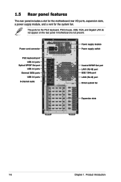
... IEEE 1394a port LAN2 (RJ-45) port 95mm system fan Expansion slots 1-6 Chapter 1: Product introduction 1.5 Rear panel features The rear panel includes a slot for the motherboard rear I/O ports, expansion slots, a power supply module, and a vent for the PS/2 keyboard, PS/2 mouse, USB, VGA, and Gigabit LAN do not appear on the...
... IEEE 1394a port LAN2 (RJ-45) port 95mm system fan Expansion slots 1-6 Chapter 1: Product introduction 1.5 Rear panel features The rear panel includes a slot for the motherboard rear I/O ports, expansion slots, a power supply module, and a vent for the PS/2 keyboard, PS/2 mouse, USB, VGA, and Gigabit LAN do not appear on the...

User Manual
Page 19
Optical drive 6. 5.25-inch drive bay 7. 7-in-1 Card Reader 8. Internal HDD bays 10. Chassis intrusion switch ASUS TW300-E5/PI4 1-7 Power supply unit 2. 95mm system fan 3. Front I/O board (hidden) 9. ASUS P5E WS Professional motherboard 4. Expansion card locks 5. 1.6 Internal features The barebone server includes the basic components as shown. 1 10 2 3 5 6 7 8 4 9 1.
Optical drive 6. 5.25-inch drive bay 7. 7-in-1 Card Reader 8. Internal HDD bays 10. Chassis intrusion switch ASUS TW300-E5/PI4 1-7 Power supply unit 2. 95mm system fan 3. Front I/O board (hidden) 9. ASUS P5E WS Professional motherboard 4. Expansion card locks 5. 1.6 Internal features The barebone server includes the basic components as shown. 1 10 2 3 5 6 7 8 4 9 1.

User Manual
Page 24
... Ensure to do so can cause you physical injury and damage motherboard components. 2-4 Chapter 2: Hardware setup Failure to unplug the power cord before installing or removing any motherboard component or connection. 2.2 Motherboard overview The barebone server comes with the P5E WS Professional motherboard already installed. Refer to the chassis by nine (9) screws as indicated...
... Ensure to do so can cause you physical injury and damage motherboard components. 2-4 Chapter 2: Hardware setup Failure to unplug the power cord before installing or removing any motherboard component or connection. 2.2 Motherboard overview The barebone server comes with the P5E WS Professional motherboard already installed. Refer to the chassis by nine (9) screws as indicated...

User Manual
Page 25
ASUS TW300-E5/PI4 2-5 To prevent damage to the left . 2. 2.3 Central Processing Unit (CPU) The motherboard comes with your left (B) until it is on your thumb (A), then move it to the socket pins, do not remove the PnP cap unless you . ... a CPU: 1. Retention tab A Load lever PnP cap B This side of the socket box should face you are installing a CPU. Locate the CPU socket on the motherboard. ® P5E WS PRO P5E WS Professional CPU Socket 775 Before installing the CPU, make sure that the socket box is facing towards you and...
ASUS TW300-E5/PI4 2-5 To prevent damage to the left . 2. 2.3 Central Processing Unit (CPU) The motherboard comes with your left (B) until it is on your thumb (A), then move it to the socket pins, do not remove the PnP cap unless you . ... a CPU: 1. Retention tab A Load lever PnP cap B This side of the socket box should face you are installing a CPU. Locate the CPU socket on the motherboard. ® P5E WS PRO P5E WS Professional CPU Socket 775 Before installing the CPU, make sure that the socket box is facing towards you and...

User Manual
Page 27
B The motherboard supports Intel® Core 2 Extreme / Core 2 Quad / Core 2 Duo Series LGA775 processors with the Intel® Enhanced Memory 64 Technology (EM64T), Enhanced Intel SpeedStep® Technology (EIST), and Hyper-Threading Technology. Close the load plate (A), then push the load lever (B) until it snaps into the retention tab. ASUS TW300-E5/PI4 2-7 Refer to the Appendix for more information on these CPU features. A 6.
B The motherboard supports Intel® Core 2 Extreme / Core 2 Quad / Core 2 Duo Series LGA775 processors with the Intel® Enhanced Memory 64 Technology (EM64T), Enhanced Intel SpeedStep® Technology (EIST), and Hyper-Threading Technology. Close the load plate (A), then push the load lever (B) until it snaps into the retention tab. ASUS TW300-E5/PI4 2-7 Refer to the Appendix for more information on these CPU features. A 6.
User Manual
Page 29
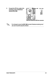
3. ASUS TW300-E5/PI4 2-9 Connect the CPU fan cable to the connector on the motherboard labeled CPU_FAN. ® P5E WS PRO CPU FAN PWM CPU FAN IN CPU FAN PWR GND CPU_FAN P5E WS Professional CPU fan connector Do not forget to plug this connector. Hardware monitoring errors can occur if you fail to connect the CPU_FAN connector!
3. ASUS TW300-E5/PI4 2-9 Connect the CPU fan cable to the connector on the motherboard labeled CPU_FAN. ® P5E WS PRO CPU FAN PWM CPU FAN IN CPU FAN PWR GND CPU_FAN P5E WS Professional CPU fan connector Do not forget to plug this connector. Hardware monitoring errors can occur if you fail to connect the CPU_FAN connector!

User Manual
Page 30
2.4 System memory 2.4.1 Overview The motherboard comes with four Double Data Rate II (DDR2) Dual Inline Memory Modules (DIMM) sockets to the table below for details. Refer to support 240-pin ...-pin DDR2 DIMM sockets Channel Channel A Channel B Sockets DIMM_A1 and DIMM_A2 DIMM_B1 and DIMM_B2 This chipset officially supports DDR2 800/667MHz. With the ASUS Super Memspeed Technology, the motherboard natively supports up to DDR2 1066MHz and provides more ratio setting items than the chipset officially supports. FSB 1333 1066 DDR2 1066 800...
2.4 System memory 2.4.1 Overview The motherboard comes with four Double Data Rate II (DDR2) Dual Inline Memory Modules (DIMM) sockets to the table below for details. Refer to support 240-pin ...-pin DDR2 DIMM sockets Channel Channel A Channel B Sockets DIMM_A1 and DIMM_A2 DIMM_B1 and DIMM_B2 This chipset officially supports DDR2 800/667MHz. With the ASUS Super Memspeed Technology, the motherboard natively supports up to DDR2 1066MHz and provides more ratio setting items than the chipset officially supports. FSB 1333 1066 DDR2 1066 800...

User Manual
Page 31
ASUS TW300-E5/PI4 2-11 You may install a maximum of 128 Mb chips or double sided x16 memory modules. • Due to chipset limitation, ... will automatically downgrade to run at DDR2-667. This limitation appears on the operating systems listed below. If this motherboard can only support up to 8 GB on Windows® Vista 32-bit / Windows® XP 32-bit operation... systems since it is recommended. • This motherboard does not support memory modules made up of 2 GB DIMMs on each slot. 64-bit Windows® XP Professional...
ASUS TW300-E5/PI4 2-11 You may install a maximum of 128 Mb chips or double sided x16 memory modules. • Due to chipset limitation, ... will automatically downgrade to run at DDR2-667. This limitation appears on the operating systems listed below. If this motherboard can only support up to 8 GB on Windows® Vista 32-bit / Windows® XP 32-bit operation... systems since it is recommended. • This motherboard does not support memory modules made up of 2 GB DIMMs on each slot. 64-bit Windows® XP Professional...

User Manual
Page 32
.... 2. Firmly insert the DIMM into a socket to avoid damaging the DIMM. • The DDR2 DIMM sockets do so can cause severe damage to both the motherboard and the components. 2.4.3 Installing a DIMM Unplug the power supply before adding or removing DIMMs or other system components. Remove the DIMM from the socket. 2 1 DDR2...
.... 2. Firmly insert the DIMM into a socket to avoid damaging the DIMM. • The DDR2 DIMM sockets do so can cause severe damage to both the motherboard and the components. 2.4.3 Installing a DIMM Unplug the power supply before adding or removing DIMMs or other system components. Remove the DIMM from the socket. 2 1 DDR2...
User Manual
Page 35
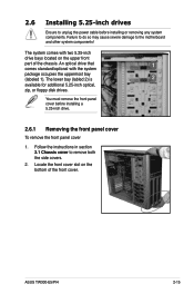
...labled 2) is 2 available for additional 5.25-inch optical, zip, or floppy disk drives. Follow the instructions in section 2.1 Chassis cover to the motherboard and other system components! You must remove the front panel cover before installing or removing any system components. The system comes with the system 1 ...damage to remove both the side covers. 2. Locate the front cover slot on the upper front part of the front cover. ASUS TW300-E5/PI4 2-15 An optical drive that comes standard/optional with two 5.25-inch drive bays located on the bottom of the chassis.
...labled 2) is 2 available for additional 5.25-inch optical, zip, or floppy disk drives. Follow the instructions in section 2.1 Chassis cover to the motherboard and other system components! You must remove the front panel cover before installing or removing any system components. The system comes with the system 1 ...damage to remove both the side covers. 2. Locate the front cover slot on the upper front part of the front cover. ASUS TW300-E5/PI4 2-15 An optical drive that comes standard/optional with two 5.25-inch drive bays located on the bottom of the chassis.

User Manual
Page 39
Slightly push down metal cover. 4. ASUS TW300-E5/PI4 2-19 Before installing the expansion card, read the documentation that you intend to the motherboard and other system components! To install an expansion card 1. Ensure to unlock it and make the necessary hardware settings for the card. 2. Lift the expansion ...
Slightly push down metal cover. 4. ASUS TW300-E5/PI4 2-19 Before installing the expansion card, read the documentation that you intend to the motherboard and other system components! To install an expansion card 1. Ensure to unlock it and make the necessary hardware settings for the card. 2. Lift the expansion ...

User Manual
Page 41
... 10 IRQ holder for PCI steering* * These IRQs are usually available for this motherboard A B C D E F G H PCI Slot 1 Shared - - - - - - - PCIe X1_1 - Shared - - USB 2.0 Controller 1 - - - - - - - IRQ assignments for PCI devices. LAN 2 (8056) - - - PCIe X16_1 Shared - - - - - - - Shared - - - - - USB Controller 6 - - - - - USB Controller 4 Shared - - - - - - - ASUS TW300-E5/PI4 2-21 Shared - - - - - PCI Slot 2 - Shared USB 2.0 Controller 2 - - Shared - - - - - Shared - - - - - - Shared...
... 10 IRQ holder for PCI steering* * These IRQs are usually available for this motherboard A B C D E F G H PCI Slot 1 Shared - - - - - - - PCIe X1_1 - Shared - - USB 2.0 Controller 1 - - - - - - - IRQ assignments for PCI devices. LAN 2 (8056) - - - PCIe X16_1 Shared - - - - - - - Shared - - - - - USB Controller 6 - - - - - USB Controller 4 Shared - - - - - - - ASUS TW300-E5/PI4 2-21 Shared - - - - - PCI Slot 2 - Shared USB 2.0 Controller 2 - - Shared - - - - - Shared - - - - - - Shared...

User Manual
Page 43
CPU_FAN PWR_FAN Rotation +12V GND CPU FAN PWM CPU FAN IN CPU FAN PWR GND ® P5E WS PRO CHA_FAN2 GND +12V Rotation CHA_FAN1 Rotation +12V GND P5E WS Professional Fan connectors 2. ASUS TW300-E5/PI4 2-23 Keep the screws for later use. Remove the system fan, and then set aside. Disconnect the chassis fan cable from the CHA_FAN1 connector on the motherboard. Locate and remove four system fan screws at the rear panel. 2.8.2 Removing the system fan To remove the system fan 1. Hold the system fan with one hand while removing the system screws. 3.
CPU_FAN PWR_FAN Rotation +12V GND CPU FAN PWM CPU FAN IN CPU FAN PWR GND ® P5E WS PRO CHA_FAN2 GND +12V Rotation CHA_FAN1 Rotation +12V GND P5E WS Professional Fan connectors 2. ASUS TW300-E5/PI4 2-23 Keep the screws for later use. Remove the system fan, and then set aside. Disconnect the chassis fan cable from the CHA_FAN1 connector on the motherboard. Locate and remove four system fan screws at the rear panel. 2.8.2 Removing the system fan To remove the system fan 1. Hold the system fan with one hand while removing the system screws. 3.

User Manual
Page 46
2.9 Connecting cables The TW300-E5/PI4 chassis includes the power and signal cables that you need to disconnect these cables unless you intend to the motherboard 1. 24-pin ATX 12V power plug 2. 4-pin ATX 12V power plug 3. Serial ATA signal cables 7. IDE signal cable 6. Card Reader ...cable 4. System panel cable 8. You do not need to connect to the motherboard, storage drives, and other devices that you will remove pre-installed components to install additional devices. • Refer to Chapter 3 for detailed ...
2.9 Connecting cables The TW300-E5/PI4 chassis includes the power and signal cables that you need to disconnect these cables unless you intend to the motherboard 1. 24-pin ATX 12V power plug 2. 4-pin ATX 12V power plug 3. Serial ATA signal cables 7. IDE signal cable 6. Card Reader ...cable 4. System panel cable 8. You do not need to connect to the motherboard, storage drives, and other devices that you will remove pre-installed components to install additional devices. • Refer to Chapter 3 for detailed ...

User Manual
Page 47
This chapter includes the motherboard layout, jumper settings, and connector locations. Motherboard info Chapter 3 This chapter gives information about the motherboard that comes with the workstation. ASUS TW300-E5/PI4 3-
This chapter includes the motherboard layout, jumper settings, and connector locations. Motherboard info Chapter 3 This chapter gives information about the motherboard that comes with the workstation. ASUS TW300-E5/PI4 3-


