User Manual
Page 3
... features 1-7 1.7 LED information 1-8 1.7.1 Front panel LED 1-8 1.7.2 LAN (RJ-45) LEDs 1-8 Chapter 2: Hardware setup 2.1 Chassis covers 2-2 2.1.1 Removing the left side cover 2-2 2.1.2 Removing the right side cover 2-3 2.2 Motherboard overview 2-4 2.3 Central Processing Unit (CPU 2-5 2.3.1 Installing the CPU 2-5 2.3.2 Installing the CPU heatsink 2-8 2.4 System memory 2-10 2.4.1 Overview 2-10 2.4.2 Memory configurations 2-11 2.4.3 Installing a DIMM 2-12 2.4.4 Removing a DIMM...
... features 1-7 1.7 LED information 1-8 1.7.1 Front panel LED 1-8 1.7.2 LAN (RJ-45) LEDs 1-8 Chapter 2: Hardware setup 2.1 Chassis covers 2-2 2.1.1 Removing the left side cover 2-2 2.1.2 Removing the right side cover 2-3 2.2 Motherboard overview 2-4 2.3 Central Processing Unit (CPU 2-5 2.3.1 Installing the CPU 2-5 2.3.2 Installing the CPU heatsink 2-8 2.4 System memory 2-10 2.4.1 Overview 2-10 2.4.2 Memory configurations 2-11 2.4.3 Installing a DIMM 2-12 2.4.4 Removing a DIMM...

User Manual
Page 4
... assignments 2-20 2.8 Removing the system fan 2-21 2.9 Connecting cables 2-22 Chapter 3: Motherboard info 3.1 Motherboard layouts 3-2 3.2 Jumper 3-5 3.3 Connectors 3-6 3.3.1 Rear panel connectors 3-6 3.3.2 Internal connectors 3-8 Chapter 4: BIOS infomation 4.1 Managing and updating your BIOS 4-2 4.1.1 ASUS Update utility 4-2 4.1.2 ASUS EZ Flash 2 utility 4-5 4.1.3 Creating a bootable floppy disk 4-6 4.1.4 AFUDOS utility 4-7 4.1.5 ASUS CrashFree BIOS 3 utility 4-9 4.2 BIOS setup program 4-10 4.2.1 BIOS menu screen 4-11...
... assignments 2-20 2.8 Removing the system fan 2-21 2.9 Connecting cables 2-22 Chapter 3: Motherboard info 3.1 Motherboard layouts 3-2 3.2 Jumper 3-5 3.3 Connectors 3-6 3.3.1 Rear panel connectors 3-6 3.3.2 Internal connectors 3-8 Chapter 4: BIOS infomation 4.1 Managing and updating your BIOS 4-2 4.1.1 ASUS Update utility 4-2 4.1.2 ASUS EZ Flash 2 utility 4-5 4.1.3 Creating a bootable floppy disk 4-6 4.1.4 AFUDOS utility 4-7 4.1.5 ASUS CrashFree BIOS 3 utility 4-9 4.2 BIOS setup program 4-10 4.2.1 BIOS menu screen 4-11...
User Manual
Page 9
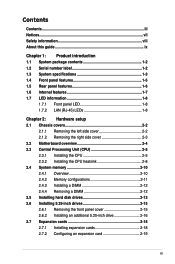
...at least basic knowledge of the workstation, including sections on front panel and rear panel specifications. 2. This chapter includes the motherboard layout, jumper settings, and connector locations. 4. Chapter 6: Driver installation This chapter provides information on how to install the... This section provides a troubleshooting guide for solving common problems when using the barebone workstation. Chapter 3: Motherboard information This chapter gives information about the motherboard that you have to change system settings through the BIOS Setup menus and describes the BIOS parameters....
...at least basic knowledge of the workstation, including sections on front panel and rear panel specifications. 2. This chapter includes the motherboard layout, jumper settings, and connector locations. 4. Chapter 6: Driver installation This chapter provides information on how to install the... This section provides a troubleshooting guide for solving common problems when using the barebone workstation. Chapter 3: Motherboard information This chapter gives information about the motherboard that you have to change system settings through the BIOS Setup menus and describes the BIOS parameters....
User Manual
Page 12
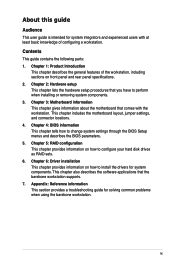
... package for the following items. Model Name Chassis Motherboard Component Accessories TW100-E5 ASUS TM-220 CASE ASSY ASUS P5N-VM WS Workstation Board (uATX, 6L) 1 x 390W Single Power Supply 1 x System Fan 1 x DVD-RW 1 x SATA Cable 1 x 7-in-1 Card Reader (optional) 3 x Internal HDD Cages 1 x Front I/O Board 1 x ASUS TW100-E5 User's Guide 1 x TW100-E5 Support CD 1 x Bag of Screws 1 x AC Power Cable...
... package for the following items. Model Name Chassis Motherboard Component Accessories TW100-E5 ASUS TM-220 CASE ASSY ASUS P5N-VM WS Workstation Board (uATX, 6L) 1 x 390W Single Power Supply 1 x System Fan 1 x DVD-RW 1 x SATA Cable 1 x 7-in-1 Card Reader (optional) 3 x Internal HDD Cages 1 x Front I/O Board 1 x ASUS TW100-E5 User's Guide 1 x TW100-E5 Support CD 1 x Bag of Screws 1 x AC Power Cable...
User Manual
Page 13
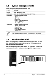
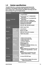
1.3 System specifications The ASUS TW100-E5 is a workstation featuring the ASUS P5N-VM WS motherboard. Supports teaming function (continued on Card (Support Hardware RAID 0, 1, 10 and 5) 3 x Internal SATA HDD Cages Networking LAN 2 x Realtek® RTL8111C Gigabit LAN controllers - Model Name Processor / System Bus supported TW100-E5 1 x Socket LGA775 Quad-Core Intel® Core™ 2 QX9000/Q9000 series (...1: SASsaby 1064E PCI-E 4-port SAS Add-on Card (Support LSI® Integrated RAID 0, 1, and 1E) Option 2: SASsaby M PCI-E 4-port SAS Add-on the next page) ASUS TW100-E5 1-3
1.3 System specifications The ASUS TW100-E5 is a workstation featuring the ASUS P5N-VM WS motherboard. Supports teaming function (continued on Card (Support Hardware RAID 0, 1, 10 and 5) 3 x Internal SATA HDD Cages Networking LAN 2 x Realtek® RTL8111C Gigabit LAN controllers - Model Name Processor / System Bus supported TW100-E5 1 x Socket LGA775 Quad-Core Intel® Core™ 2 QX9000/Q9000 series (...1: SASsaby 1064E PCI-E 4-port SAS Add-on Card (Support LSI® Integrated RAID 0, 1, and 1E) Option 2: SASsaby M PCI-E 4-port SAS Add-on the next page) ASUS TW100-E5 1-3

User Manual
Page 16
... switch PS/2 keyboard / mouse combo port Coaxial S/PDIF Out port LAN2 (RJ-45) port DVI-I /O ports, expansion slots, a power supply module, and a vent for the motherboard rear I port (Single Link) System fan LAN1 (RJ-45) port Expansion slots 1-6 Chapter 1: Product introduction The PS/2 keyboard / mouse combo port, USB ports, DVI-I ports...
... switch PS/2 keyboard / mouse combo port Coaxial S/PDIF Out port LAN2 (RJ-45) port DVI-I /O ports, expansion slots, a power supply module, and a vent for the motherboard rear I port (Single Link) System fan LAN1 (RJ-45) port Expansion slots 1-6 Chapter 1: Product introduction The PS/2 keyboard / mouse combo port, USB ports, DVI-I ports...
User Manual
Page 17
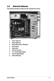
1.6 Internal features The barebone workstation includes the basic components as shown. 1 4 2 3 5 6 7 9 8 1. CPU Heatsink 5. Internal HDD bays ASUS TW100-E5 1-7 Power supply unit 2. 92mm system fan 3. ASUS P5N-VM WS motherboard 4. Optical drive 6. 5.25-inch drive bay 7. 7-in-1 Card Reader (hidden) 8. Front I/O board (hidden) 9.
1.6 Internal features The barebone workstation includes the basic components as shown. 1 4 2 3 5 6 7 9 8 1. CPU Heatsink 5. Internal HDD bays ASUS TW100-E5 1-7 Power supply unit 2. 92mm system fan 3. ASUS P5N-VM WS motherboard 4. Optical drive 6. 5.25-inch drive bay 7. 7-in-1 Card Reader (hidden) 8. Front I/O board (hidden) 9.

User Manual
Page 22
Failure to the chassis by eight (8) screws as indicated by the circles in the illustration below. 2.2 Motherboard overview The barebone server comes with the P5N-VM WS motherboard already installed. The motherboard is secured to do so can cause you physical injury and damage motherboard components. 2-4 Chapter 2: Hardware setup Place this side towards the rear of the chassis Ensure to Chapter 3: Motherboard information for detailed information on the motherboard. Refer to unplug the power cord before installing or removing any motherboard component or connection.
Failure to the chassis by eight (8) screws as indicated by the circles in the illustration below. 2.2 Motherboard overview The barebone server comes with the P5N-VM WS motherboard already installed. The motherboard is secured to do so can cause you physical injury and damage motherboard components. 2-4 Chapter 2: Hardware setup Place this side towards the rear of the chassis Ensure to Chapter 3: Motherboard information for detailed information on the motherboard. Refer to unplug the power cord before installing or removing any motherboard component or connection.

User Manual
Page 23
2.3 Central Processing Unit (CPU) The motherboard comes with your left (B) until it to a 135º angle. 4. B Load lever 3. Lift the load plate with a surface mount LGA775 socket designed for the Intel&#... in the direction of the arrow to the left . 2. Press the load lever with your thumb (A), then move it is on the motherboard. PnP cap Load plate 4B 4A 3 ASUS TW100-E5 2-5 Before installing the CPU, make sure that the socket box is facing towards you are installing a CPU. Locate the CPU socket on...
2.3 Central Processing Unit (CPU) The motherboard comes with your left (B) until it to a 135º angle. 4. B Load lever 3. Lift the load plate with a surface mount LGA775 socket designed for the Intel&#... in the direction of the arrow to the left . 2. Press the load lever with your thumb (A), then move it is on the motherboard. PnP cap Load plate 4B 4A 3 ASUS TW100-E5 2-5 Before installing the CPU, make sure that the socket box is facing towards you are installing a CPU. Locate the CPU socket on...

User Manual
Page 27
Connect the CPU fan cable to connect the CPU_FAN connector! Do not forget to the connector on the motherboard labeled CPU_FAN. ASUS TW100-E5 2-9 3. Hardware monitoring errors can occur if you fail to plug this connector.
Connect the CPU fan cable to connect the CPU_FAN connector! Do not forget to the connector on the motherboard labeled CPU_FAN. ASUS TW100-E5 2-9 3. Hardware monitoring errors can occur if you fail to plug this connector.

User Manual
Page 28
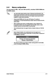
The figure illustrates the location of the DDR2 DIMM sockets: Channel Channel A Channel B Sockets DIMM_A1 and DIMM_A2 DIMM_B1 and DIMM_B2 Recommend memory configuration Mode Single-channel Dual-channel (1) Dual-channel (2) Full Sockets DIMM_B1 populated populated populated DIMM_B2 populated populated DIMM_A1 populated populated populated DIMM_A2 populated populated 2-10 Chapter 2: Hardware setup 2.4 System memory 2.4.1 Overview The motherboard comes with four Double Data Rate II (DDR2) Dual Inline Memory Modules (DIMM) sockets to support 240-pin DDR2 modules.
The figure illustrates the location of the DDR2 DIMM sockets: Channel Channel A Channel B Sockets DIMM_A1 and DIMM_A2 DIMM_B1 and DIMM_B2 Recommend memory configuration Mode Single-channel Dual-channel (1) Dual-channel (2) Full Sockets DIMM_B1 populated populated populated DIMM_B2 populated populated DIMM_A1 populated populated populated DIMM_A2 populated populated 2-10 Chapter 2: Hardware setup 2.4 System memory 2.4.1 Overview The motherboard comes with four Double Data Rate II (DDR2) Dual Inline Memory Modules (DIMM) sockets to support 240-pin DDR2 modules.
User Manual
Page 29
... excess memory from the same vendor. • When installing total memory of 128 Mb chips. • Due to chipset limitation, this motherboard can only support up of 4GB capacity or more, Windows 32bit operation system may ...to 8 GB on the operating systems listed below. For optimum compatibility, it is recommended. • This motherboard does not support memory modules made up to work stably under full loading (4 DIMMs) setting. The system ... mapped for the dual-channel configuration. ASUS TW100-E5 2-11 You may install varying memory sizes in Channel A and Channel B.
... excess memory from the same vendor. • When installing total memory of 128 Mb chips. • Due to chipset limitation, this motherboard can only support up of 4GB capacity or more, Windows 32bit operation system may ...to 8 GB on the operating systems listed below. For optimum compatibility, it is recommended. • This motherboard does not support memory modules made up to work stably under full loading (4 DIMMs) setting. The system ... mapped for the dual-channel configuration. ASUS TW100-E5 2-11 You may install varying memory sizes in Channel A and Channel B.

User Manual
Page 30
... may cause severe damage to unplug the power supply before adding or removing DIMMs or other system components. 2.4.3 Installing a DIMM Make sure to both the motherboard and the components. 1. Simultaneously press the retaining clips outward to unlock the DIMM. 1 1 DDR2 DIMM notch Support the DIMM lightly with your fingers when pressing...
... may cause severe damage to unplug the power supply before adding or removing DIMMs or other system components. 2.4.3 Installing a DIMM Make sure to both the motherboard and the components. 1. Simultaneously press the retaining clips outward to unlock the DIMM. 1 1 DDR2 DIMM notch Support the DIMM lightly with your fingers when pressing...

User Manual
Page 32
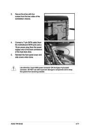
DO NOT use both to prevent damage to components and to keep the system from the power supply unit) to the back connectors of the hard disk drive. Use either the 15-pin SATA power connector OR the legacy 4-pin power connector. Connect a 7-pin SATA cable (from the motherboard SATA port) and a 15-pin power plug (from becoming unstable. 2-14 Chapter 2: Hardware setup 5.
DO NOT use both to prevent damage to components and to keep the system from the power supply unit) to the back connectors of the hard disk drive. Use either the 15-pin SATA power connector OR the legacy 4-pin power connector. Connect a 7-pin SATA cable (from the motherboard SATA port) and a 15-pin power plug (from becoming unstable. 2-14 Chapter 2: Hardware setup 5.

User Manual
Page 33
... the chassis. Gently lift the hooked tabs to the motherboard and other system components! Failure to do so may cause severe damage to release the front panel cover from the chassis. The front panel cover is available for 2 additional 5.25-inch drive. ASUS TW100-E5 2-15 2.6 Installing 5.25-inch drives Ensure to remove the...
... the chassis. Gently lift the hooked tabs to the motherboard and other system components! Failure to do so may cause severe damage to release the front panel cover from the chassis. The front panel cover is available for 2 additional 5.25-inch drive. ASUS TW100-E5 2-15 2.6 Installing 5.25-inch drives Ensure to remove the...
User Manual
Page 35
Use either the 15-pin SATA power connector OR the legacy 4-pin power connector. Connect a 7-pin SATA cable (from the motherboard SATA port) and a 15-pin power plug (from the power supply unit) to keep the system from the two sides of the hard disk drive. 5. 3. ASUS TW100-E5 2-17 DO NOT use both to prevent damage to components and to the back connectors of the workstation chassis. 4. Secure the drive with four screws from becoming unstable. Reinstall the front panel cover and side covers when done.
Use either the 15-pin SATA power connector OR the legacy 4-pin power connector. Connect a 7-pin SATA cable (from the motherboard SATA port) and a 15-pin power plug (from the power supply unit) to keep the system from the two sides of the hard disk drive. 5. 3. ASUS TW100-E5 2-17 DO NOT use both to prevent damage to components and to the back connectors of the workstation chassis. 4. Secure the drive with four screws from becoming unstable. Reinstall the front panel cover and side covers when done.

User Manual
Page 36
Lay the system on its metal bracket to the motherboard and other system components! Select the slot that came with one PCI Express x16 slot (x16 link), one PCI Express x4 slot (x1 link), one ...
Lay the system on its metal bracket to the motherboard and other system components! Select the slot that came with one PCI Express x16 slot (x16 link), one PCI Express x4 slot (x1 link), one ...

User Manual
Page 38
... port* 13 8 Numeric data processor 14 9 IRQ holder for PCI steering* 15 10 IRQ holder for PCI steering* * These IRQs are usually available for this motherboard LNKC LN0A LN3A LN4A LN5A LN6A SGRU LUB0 LUB2 UB11 UB12 LSA0 LAZA PCI slot Shared - - - - - - - - - - - -
... port* 13 8 Numeric data processor 14 9 IRQ holder for PCI steering* 15 10 IRQ holder for PCI steering* * These IRQs are usually available for this motherboard LNKC LN0A LN3A LN4A LN5A LN6A SGRU LUB0 LUB2 UB11 UB12 LSA0 LAZA PCI slot Shared - - - - - - - - - - - -

User Manual
Page 39
To remove the system fan 1. Locate and remove four system fan screws at the rear panel. Keep the screws for later use. ASUS TW100-E5 2-21 Hold the system fan with one hand while removing the system screws. 3. Remove the system fan, and then set aside. Disconnect the chassis fan cable from the CHA_FAN2 connector on the motherboard. 2. 2.8 Removing the system fan You may need to remove the system fan. This section tells how to remove previously installed system components when installing or removing other system components, or when replacing a defective component.
To remove the system fan 1. Locate and remove four system fan screws at the rear panel. Keep the screws for later use. ASUS TW100-E5 2-21 Hold the system fan with one hand while removing the system screws. 3. Remove the system fan, and then set aside. Disconnect the chassis fan cable from the CHA_FAN2 connector on the motherboard. 2. 2.8 Removing the system fan You may need to remove the system fan. This section tells how to remove previously installed system components when installing or removing other system components, or when replacing a defective component.

User Manual
Page 40
You do not need to connect to the motherboard, storage drives, and other devices that you will remove pre-installed components to install additional devices. • Refer to Chapter 3 for detailed information on the ... 6. Card Reader cable 4. Front panel USB 2.0 cable 5. System fan cable 2-22 Chapter 2: Hardware setup System panel cable 7. 2.9 Connecting cables The TW100-E5 chassis includes the power and signal cables that you need to disconnect these cables unless you intend to the motherboard 1. 20-pin ATX 12V power plug 2. 4-pin ATX 12V power plug 3.
You do not need to connect to the motherboard, storage drives, and other devices that you will remove pre-installed components to install additional devices. • Refer to Chapter 3 for detailed information on the ... 6. Card Reader cable 4. Front panel USB 2.0 cable 5. System fan cable 2-22 Chapter 2: Hardware setup System panel cable 7. 2.9 Connecting cables The TW100-E5 chassis includes the power and signal cables that you need to disconnect these cables unless you intend to the motherboard 1. 20-pin ATX 12V power plug 2. 4-pin ATX 12V power plug 3.


