User Guide
Page 8
...all the manuals included with the server package. • Before using the server, make sure all cables are correctly connected and the power cables are not damaged. Ask for the user's safety. viii Operation Safety • Servicing of this product or units is heavy. ... devices to the manufacturer's instructions. Danger of used batteries according to or from the electrical outlet before you service. • If the power supply is incorrectly replaced. If possible, disconnect all attached devices are connected. CD-ROM Drive Safety Warning CLASS 1 LASER PRODUCT Heavy System CAUTION...
...all the manuals included with the server package. • Before using the server, make sure all cables are correctly connected and the power cables are not damaged. Ask for the user's safety. viii Operation Safety • Servicing of this product or units is heavy. ... devices to the manufacturer's instructions. Danger of used batteries according to or from the electrical outlet before you service. • If the power supply is incorrectly replaced. If possible, disconnect all attached devices are connected. CD-ROM Drive Safety Warning CLASS 1 LASER PRODUCT Heavy System CAUTION...
User Guide
Page 12
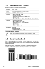
... members can then offer a quicker and satisfying solution to your system package for the following items. Model Name TS500-E6/PS4 Chassis ASUS T50A Pedestal 5U Rackmount Chassis Motherboard ASUS Z8NA-D6 Server Board Component 1 x 470W Single Power Supply 4 x hot-swap HDD trays 1 x SAS/SATA2 Backplane with 4 x SATA Cables 1 x Front I/O Board 2 x System Fans (Front: 1 x 80mm x 38mm; 1.1 System...
... members can then offer a quicker and satisfying solution to your system package for the following items. Model Name TS500-E6/PS4 Chassis ASUS T50A Pedestal 5U Rackmount Chassis Motherboard ASUS Z8NA-D6 Server Board Component 1 x 470W Single Power Supply 4 x hot-swap HDD trays 1 x SAS/SATA2 Backplane with 4 x SATA Cables 1 x Front I/O Board 2 x System Fans (Front: 1 x 80mm x 38mm; 1.1 System...
User Guide
Page 14
... change without any notice) Optional anti-virus CD Pack Optional ASMB4-iKVM for KVM-over-IP support ASUS ASWM 2.0® 445mm x 217.5mm x 545mm 17 Kg 470W (80+) Single Power Supply Operation temperature: 10°C-35°C / Non operation temperature: -40°C-70°C Non ...Support Anti-virus Software Out of Band Management Solution Remote Hardware Software Dimension (HH x WW x DD) Net Weight Kg (CPU, DRAM & HDD not inclu ded) Power Supply Environment 2 x Intel® 82574L Aspeed AST2050 8MB 3 x 5.25" media bays (Options: No ODD / DVD-ROM / DVD-RW) 1 x External Serial ...
... change without any notice) Optional anti-virus CD Pack Optional ASMB4-iKVM for KVM-over-IP support ASUS ASWM 2.0® 445mm x 217.5mm x 545mm 17 Kg 470W (80+) Single Power Supply Operation temperature: 10°C-35°C / Non operation temperature: -40°C-70°C Non ...Support Anti-virus Software Out of Band Management Solution Remote Hardware Software Dimension (HH x WW x DD) Net Weight Kg (CPU, DRAM & HDD not inclu ded) Power Supply Environment 2 x Intel® 82574L Aspeed AST2050 8MB 3 x 5.25" media bays (Options: No ODD / DVD-ROM / DVD-RW) 1 x External Serial ...
User Guide
Page 16
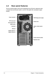
Power connector PS/2 mouse port PS/2 keyboard port USB 2.0 ports Serial port VGA port Gigabit LAN port 1 Gigabit LAN port 2 470W Single power supply Chassis lock 120mm x 38mm system fan Chassis intrusion switch Expansion slots 1-6 Chapter 1: Product introduction 1.5 Rear panel features The rear panel includes a slot for the motherboard rear I/O ports, expansion slots, a chassis lock and intrusion switch, a vent for the system fan, and power supply module.
Power connector PS/2 mouse port PS/2 keyboard port USB 2.0 ports Serial port VGA port Gigabit LAN port 1 Gigabit LAN port 2 470W Single power supply Chassis lock 120mm x 38mm system fan Chassis intrusion switch Expansion slots 1-6 Chapter 1: Product introduction 1.5 Rear panel features The rear panel includes a slot for the motherboard rear I/O ports, expansion slots, a chassis lock and intrusion switch, a vent for the system fan, and power supply module.
User Guide
Page 17
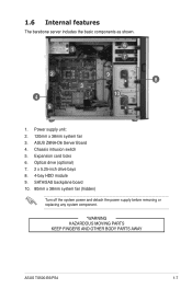
Power supply unit: 2. 120mm x 38mm system fan 3. Optical drive (optional) 7. 2 x 5.25-inch drive bays 8. 4-bay HDD module 9. ASUS Z8NA-D6 Server Board 4. SATA/SAS backplane board 10. 80mm x 38mm system fan (hidden) Turn off the system power and detach the power supply before removing or replacing any system component. *WARNING HAZARDOUS MOVING PARTS KEEP FINGERS AND OTHER BODY PARTS AWAY ASUS TS500-E6/PS4 1-7 Expansion card locks 6. Chassis intrusion switch 5. 1.6 Internal features The barebone server includes the basic components as shown. 1 6 7 2 9 8 3 4 10 5 1.
Power supply unit: 2. 120mm x 38mm system fan 3. Optical drive (optional) 7. 2 x 5.25-inch drive bays 8. 4-bay HDD module 9. ASUS Z8NA-D6 Server Board 4. SATA/SAS backplane board 10. 80mm x 38mm system fan (hidden) Turn off the system power and detach the power supply before removing or replacing any system component. *WARNING HAZARDOUS MOVING PARTS KEEP FINGERS AND OTHER BODY PARTS AWAY ASUS TS500-E6/PS4 1-7 Expansion card locks 6. Chassis intrusion switch 5. 1.6 Internal features The barebone server includes the basic components as shown. 1 6 7 2 9 8 3 4 10 5 1.
User Guide
Page 30
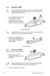
... socket such that it flips out with your fingers when pressing the retaining clips. Locked Retaining Clip 2.3.4 Removing a DIMM Follow these steps to unplug the power supply before adding or removing DIMMs or other system components. Failure to do so may cause severe damage to avoid damaging the DIMM. 3. Firmly insert the...
... socket such that it flips out with your fingers when pressing the retaining clips. Locked Retaining Clip 2.3.4 Removing a DIMM Follow these steps to unplug the power supply before adding or removing DIMMs or other system components. Failure to do so may cause severe damage to avoid damaging the DIMM. 3. Firmly insert the...
User Guide
Page 32
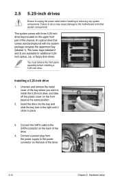
Connect a power plug from the power supply to unplug the power cable before installing a 5.25-inch drive. 2.5 5.25-inch drives Ensure to the power connector on the back of the drive. 43 2-12 Chapter 2: Hardware setup Failure to do so may cause damage to the right until it clicks ...
Connect a power plug from the power supply to unplug the power cable before installing a 5.25-inch drive. 2.5 5.25-inch drives Ensure to the power connector on the back of the drive. 43 2-12 Chapter 2: Hardware setup Failure to do so may cause damage to the right until it clicks ...
User Guide
Page 42
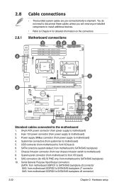
... I /O board) 6. Motherboard connections 3 24 1 4 4 4 5 6 7 8 10 9 Standard cables connected to the motherboard 1. 24-pin ATX power connector (from power supply to motherboard) 2. 8-pin 12V power connector (from motherboard to front I /O board) 9. System panel connector (from motherboard SGPIO3 to Chapter 4 for ASUS PIKE only; 2.8 2.8.1 Cable connections • The bundled system cables are pre-connected before shipment. You...
... I /O board) 6. Motherboard connections 3 24 1 4 4 4 5 6 7 8 10 9 Standard cables connected to the motherboard 1. 24-pin ATX power connector (from power supply to motherboard) 2. 8-pin 12V power connector (from motherboard to front I /O board) 9. System panel connector (from motherboard SGPIO3 to Chapter 4 for ASUS PIKE only; 2.8 2.8.1 Cable connections • The bundled system cables are pre-connected before shipment. You...
User Guide
Page 44
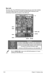
... and SATA/SAS interfaces for the motherboard Serial ATA connectors or the SAS card. Back side The back side of the power supply Connects to SATA/SAS connectors on the motherboard Move the SGPIO_SEL1 jumper on the motherboard Connects to 2-3 when installing the PIKE RAID card. 2-24 Chapter 2: ...
... and SATA/SAS interfaces for the motherboard Serial ATA connectors or the SAS card. Back side The back side of the power supply Connects to SATA/SAS connectors on the motherboard Move the SGPIO_SEL1 jumper on the motherboard Connects to 2-3 when installing the PIKE RAID card. 2-24 Chapter 2: ...
User Guide
Page 55
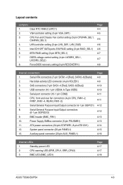
...(10-1 pin COM2) 6. Layout contents Jumpers 1. Standby power LED 2. DDR3 voltage control setting (4-pin LVDDR3_SEL1, LVDDR3_SEL2) 8. Serial General Purpose Input/Output connector (6-1 pin SGPIO1) 8. BMC LED (BMC_LED1) Page 4-17 4-17 4-18 ASUS TS500-E6/PS4 4-3 Hard disk activity LED connector (4-pin HDLED1) 3.... CPU, front and rear fan connectors (4-pin CPU_FAN1-2, FRNT_FAN1-4, REAR_FAN1-2) 7. Clear RTC RAM (CLRTC1) 2. LAN controller setting (3-pin LAN_SW1, LAN_SW2) 5. SAS connectors (7-pin SAS1-4 [Red], SAS5-8 [Blue]) 4. Power Supply SMBus connector (5-pin PSUSMB1) 11.
...(10-1 pin COM2) 6. Layout contents Jumpers 1. Standby power LED 2. DDR3 voltage control setting (4-pin LVDDR3_SEL1, LVDDR3_SEL2) 8. Serial General Purpose Input/Output connector (6-1 pin SGPIO1) 8. BMC LED (BMC_LED1) Page 4-17 4-17 4-18 ASUS TS500-E6/PS4 4-3 Hard disk activity LED connector (4-pin HDLED1) 3.... CPU, front and rear fan connectors (4-pin CPU_FAN1-2, FRNT_FAN1-4, REAR_FAN1-2) 7. Clear RTC RAM (CLRTC1) 2. LAN controller setting (3-pin LAN_SW1, LAN_SW2) 5. SAS connectors (7-pin SAS1-4 [Red], SAS5-8 [Blue]) 4. Power Supply SMBus connector (5-pin PSUSMB1) 11.
User Guide
Page 65
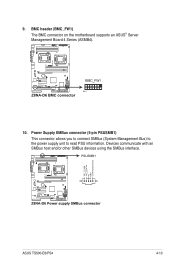
ASUS TS500-E6/PS4 4-13 Power Supply SMBus connector (5-pin PSUSMB1) This connector allows you to connect SMBus (System Management Bus) to the power supply unit to read PSU information. BMC header (BMC_FW1) The BMC connector on the motherboard supports an ASUS® Server Management Board 4 Series (ASMB4). 10. 9. Devices communicate with an SMBus host and/or other SMBus devices using the SMBus interface.
ASUS TS500-E6/PS4 4-13 Power Supply SMBus connector (5-pin PSUSMB1) This connector allows you to connect SMBus (System Management Bus) to the power supply unit to read PSU information. BMC header (BMC_FW1) The BMC connector on the motherboard supports an ASUS® Server Management Board 4 Series (ASMB4). 10. 9. Devices communicate with an SMBus host and/or other SMBus devices using the SMBus interface.

User Guide
Page 66
.... 11. otherwise, the system will not boot up if the power is recommended when configuring a system with a higher power output is inadequate. • Ensure that your power supply unit (PSU) can provide at least the minimum power required by your system (450W or above; 12V1 ≥18A.)....Motherboard information The system may become unstable or may not boot up . • Use of a PSU with more power-consuming devices. ATX power connectors (24-pin ATXPWR1, 8-pin ATX12V1) These connectors are designed to connect the 24+8-pin power plugs; The power supply plugs are for an SSI & ATX...
.... 11. otherwise, the system will not boot up if the power is recommended when configuring a system with a higher power output is inadequate. • Ensure that your power supply unit (PSU) can provide at least the minimum power required by your system (450W or above; 12V1 ≥18A.)....Motherboard information The system may become unstable or may not boot up . • Use of a PSU with more power-consuming devices. ATX power connectors (24-pin ATXPWR1, 8-pin ATX12V1) These connectors are designed to connect the 24+8-pin power plugs; The power supply plugs are for an SSI & ATX...


