User Guide
Page 6
... Options 6-30 Exiting the Intel® Matrix Storage Manager 6-31 6.3.7 Rebuilding the RAID 6-31 6.3.8 Setting the Boot array in the BIOS Setup Utility 6-33 Chapter 7: Driver installation 7.1 RAID driver installation 7-2 7.1.1 Creating a RAID driver disk 7-2 7.1.2 Installing the RAID controller driver 7-5 7.2 Intel® chipset device installation 7-13 7.3 LAN driver installation 7-15 7.4 VGA driver installation 7-18 7.5 Management applications and utilities installation 7-20 7.5.1 Running the support DVD 7-20 7.5.2 Drivers menu 7-20 7.5.3 Utilities menu 7-21 7.5.4 Make disk...
... Options 6-30 Exiting the Intel® Matrix Storage Manager 6-31 6.3.7 Rebuilding the RAID 6-31 6.3.8 Setting the Boot array in the BIOS Setup Utility 6-33 Chapter 7: Driver installation 7.1 RAID driver installation 7-2 7.1.1 Creating a RAID driver disk 7-2 7.1.2 Installing the RAID controller driver 7-5 7.2 Intel® chipset device installation 7-13 7.3 LAN driver installation 7-15 7.4 VGA driver installation 7-18 7.5 Management applications and utilities installation 7-20 7.5.1 Running the support DVD 7-20 7.5.2 Drivers menu 7-20 7.5.3 Utilities menu 7-21 7.5.4 Make disk...
User Guide
Page 9
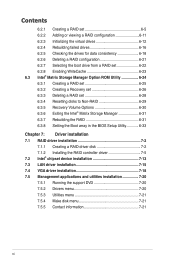
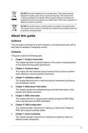
... throw the mercury-containing button cell battery in municipal waste. This symbol of the server, including sections on front panel and rear panel specifications. 2. ix Chapter 4: Motherboard information This chapter includes the motherboard layout and brief descriptions of the jumpers and internal connectors. 5. Chapter 6: RAID configuration This chapter provides instructions for setting up, creating and configuring RAID sets using the available utilities. 7 Chapter 7: Driver installation This chapter provides instructions for installing the necessary drivers for disposal of...
... throw the mercury-containing button cell battery in municipal waste. This symbol of the server, including sections on front panel and rear panel specifications. 2. ix Chapter 4: Motherboard information This chapter includes the motherboard layout and brief descriptions of the jumpers and internal connectors. 5. Chapter 6: RAID configuration This chapter provides instructions for setting up, creating and configuring RAID sets using the available utilities. 7 Chapter 7: Driver installation This chapter provides instructions for installing the necessary drivers for disposal of...
User Guide
Page 10
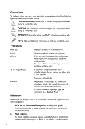
.... References Example: At the DOS prompt, type the command line: format A:/S Refer to complete a task. ASUS websites The ASUS websites worldwide provide updated information for product and software updates. 1. ASUS Server Web-based Management (ASWM) user guide This manual tells how to select. Typography Bold text Indicates a menu or an item to set up and use the proprietary ASUS server management utility. 2. Italics Used to complete a task. CAUTION: Information to...
.... References Example: At the DOS prompt, type the command line: format A:/S Refer to complete a task. ASUS websites The ASUS websites worldwide provide updated information for product and software updates. 1. ASUS Server Web-based Management (ASWM) user guide This manual tells how to select. Typography Bold text Indicates a menu or an item to set up and use the proprietary ASUS server management utility. 2. Italics Used to complete a task. CAUTION: Information to...
User Guide
Page 13
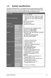
... I/O Hub Intel ICH10R I = internal HDD Bays A or S = hot- 4 x Hot-swap 3.5" HDD Bays swappable (continued on the next page) ASUS TS500-E6/PS4 1-3 Supports RAID 0,1,5,10 & 6 ASUS PIKE 6480 SAS RAID card - Supports software RAID 0, 1 & 10 Storage Optional: ASUS PIKE 1064E 4-port SAS RAID card - Supports RAID 0,1,5 & 10 I /O controller ASUS Features Smart Fan ASWM2.0 √ √ Total Slots 6 (3-channel per CPU, 3 DIMMs per CPU) Capacity Maximum up to 48GB (RDIMM) Maximum up to 24GB (UDIMM) Memory Memory Type DDR3 1333 / 1066 / 800...
... I/O Hub Intel ICH10R I = internal HDD Bays A or S = hot- 4 x Hot-swap 3.5" HDD Bays swappable (continued on the next page) ASUS TS500-E6/PS4 1-3 Supports RAID 0,1,5,10 & 6 ASUS PIKE 6480 SAS RAID card - Supports software RAID 0, 1 & 10 Storage Optional: ASUS PIKE 1064E 4-port SAS RAID card - Supports RAID 0,1,5 & 10 I /O controller ASUS Features Smart Fan ASWM2.0 √ √ Total Slots 6 (3-channel per CPU, 3 DIMMs per CPU) Capacity Maximum up to 48GB (RDIMM) Maximum up to 24GB (UDIMM) Memory Memory Type DDR3 1333 / 1066 / 800...
User Guide
Page 15
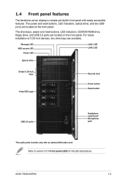
... LED HDD access LED Power LED LAN1 LED LAN2 LED Optical drive Empty 5.25-inch bays 4-bay HDD cage Security lock Power button Reset button USB 2.0 ports Headphone output jack* Microphone jack* *The audio jacks function only with easily accessible features. The power and reset buttons, LED indicators, optical drive, and two USB ports are located on the front panel. For future installation of 5.25-inch devices, two drive bays are available. ASUS TS500-E6/PS4 1-5 1.4 Front panel features The barebone server displays a simple yet stylish front panel with an optional...
... LED HDD access LED Power LED LAN1 LED LAN2 LED Optical drive Empty 5.25-inch bays 4-bay HDD cage Security lock Power button Reset button USB 2.0 ports Headphone output jack* Microphone jack* *The audio jacks function only with easily accessible features. The power and reset buttons, LED indicators, optical drive, and two USB ports are located on the front panel. For future installation of 5.25-inch devices, two drive bays are available. ASUS TS500-E6/PS4 1-5 1.4 Front panel features The barebone server displays a simple yet stylish front panel with an optional...
User Guide
Page 17
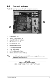
Expansion card locks 6. SATA/SAS backplane board 10. 80mm x 38mm system fan (hidden) Turn off the system power and detach the power supply before removing or replacing any system component. *WARNING HAZARDOUS MOVING PARTS KEEP FINGERS AND OTHER BODY PARTS AWAY ASUS TS500-E6/PS4 1-7 Power supply unit: 2. 120mm x 38mm system fan 3. 1.6 Internal features The barebone server includes the basic components as shown. 1 6 7 2 9 8 3 4 10 5 1. Optical drive (optional) 7. 2 x 5.25-inch drive bays 8. 4-bay HDD module 9. Chassis intrusion switch 5. ASUS Z8NA-D6 Server Board 4.
Expansion card locks 6. SATA/SAS backplane board 10. 80mm x 38mm system fan (hidden) Turn off the system power and detach the power supply before removing or replacing any system component. *WARNING HAZARDOUS MOVING PARTS KEEP FINGERS AND OTHER BODY PARTS AWAY ASUS TS500-E6/PS4 1-7 Power supply unit: 2. 120mm x 38mm system fan 3. 1.6 Internal features The barebone server includes the basic components as shown. 1 6 7 2 9 8 3 4 10 5 1. Optical drive (optional) 7. 2 x 5.25-inch drive bays 8. 4-bay HDD module 9. Chassis intrusion switch 5. ASUS Z8NA-D6 Server Board 4.
User Guide
Page 27
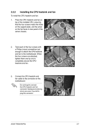
... fan. 3. ASUS TS500-E6/PS4 2-7 Twist each of the server chassis. 2. Hardware monitoring errors can occur if you fail to connect the CPU heatsink and fan connector! Place the CPU heatsink and fan on top of the installed CPU, ensuring that the four screws match the holes on the support plate, and the arrow on the motherboard. 2.2.2 Installing the CPU heatsink and fan To install the CPU heatsink and fan: 1. Do not forget to plug this connector...
... fan. 3. ASUS TS500-E6/PS4 2-7 Twist each of the server chassis. 2. Hardware monitoring errors can occur if you fail to connect the CPU heatsink and fan connector! Place the CPU heatsink and fan on top of the installed CPU, ensuring that the four screws match the holes on the support plate, and the arrow on the motherboard. 2.2.2 Installing the CPU heatsink and fan To install the CPU heatsink and fan: 1. Do not forget to plug this connector...
User Guide
Page 39
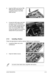
... RAID card slot. 4. 3. ASUS TS500-E6/PS4 2-19 Insert the RAID card into the PIKE RAID card slot. Ensure that it is completely seated on the motherboard. 2. For incoming PIKE 1078E, connect the cable to the connectos labeled SAS1-8 (red and blue). 2.7.3 Installing i Button Follow the steps below to the connectors labeled SAS1-4 (red). You need to the SAS connectors on your motherboard. 1. Connect the SAS cable to install I Button before using PIKE 1078 functions. Locate the I Button...
... RAID card slot. 4. 3. ASUS TS500-E6/PS4 2-19 Insert the RAID card into the PIKE RAID card slot. Ensure that it is completely seated on the motherboard. 2. For incoming PIKE 1078E, connect the cable to the connectos labeled SAS1-8 (red and blue). 2.7.3 Installing i Button Follow the steps below to the connectors labeled SAS1-4 (red). You need to the SAS connectors on your motherboard. 1. Connect the SAS cable to install I Button before using PIKE 1078 functions. Locate the I Button...
User Guide
Page 41
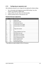
Refer to the card. ASUS TS500-E6/PS4 2-21 Install the software drivers for ISA or PCI devices. Programmable Interrupt 3* 11 Communications Port (COM2) 4* 12 Communications Port (COM1) 5* 13 -- 6 14 Floppy Disk Controller 7* 15 -- 8 3 System CMOS/Real Time Clock 9* 4 ACPI Mode when used 10* 5 IRQ Holder for PCI Steering 11* 6 IRQ Holder for PCI Steering 12* 7 PS/2 Compatible Mouse Port 13 8 Numeric Data Processor 14* 9 Primary IDE Channel 15* 10 Secondary IDE Channel...
Refer to the card. ASUS TS500-E6/PS4 2-21 Install the software drivers for ISA or PCI devices. Programmable Interrupt 3* 11 Communications Port (COM2) 4* 12 Communications Port (COM1) 5* 13 -- 6 14 Floppy Disk Controller 7* 15 -- 8 3 System CMOS/Real Time Clock 9* 4 ACPI Mode when used 10* 5 IRQ Holder for PCI Steering 11* 6 IRQ Holder for PCI Steering 12* 7 PS/2 Compatible Mouse Port 13 8 Numeric Data Processor 14* 9 Primary IDE Channel 15* 10 Secondary IDE Channel...
User Guide
Page 43
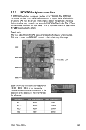
...;3 CON�4 ASUS TS500-E6/PS4 2-23 HDD1 HDD2 HDD3 Drive status LEDs HDD4 Each SATA/SAS connector is labeled (HDD1, HDD2, HDD3, HDD4) so you can easily determine their counterpart connectors at the back side of the SATA/SAS backplane faces the front panel when installed. The LEDs on the backplane connect to the front panel LEDs to support Serial ATA hard disk drives and SAS hard disk drives. 2.8.2 SATA/SAS backplane connections A SATA/SAS backplane...
...;3 CON�4 ASUS TS500-E6/PS4 2-23 HDD1 HDD2 HDD3 Drive status LEDs HDD4 Each SATA/SAS connector is labeled (HDD1, HDD2, HDD3, HDD4) so you can easily determine their counterpart connectors at the back side of the SATA/SAS backplane faces the front panel when installed. The LEDs on the backplane connect to the front panel LEDs to support Serial ATA hard disk drives and SAS hard disk drives. 2.8.2 SATA/SAS backplane connections A SATA/SAS backplane...
User Guide
Page 55
...]) 4. USB connector (10-1 pin USB34; A-Type USB5) 5. CPU, front and rear fan connectors (4-pin CPU_FAN1-2, FRNT_FAN1-4, REAR_FAN1-2) 7. Power Supply SMBus connector (5-pin PSUSMB1) 11. ATX power connectors (24-pini ATXPWR1, 8-pin ATX12V1) 12. Auxiliary panel connector (20-pin AUX_PANEL1) Page 4-9 4-9 4-10 4-10 4-11 4-11 4-12 4-12 4-13 4-13 4-14 4-15 4-16 Internal LEDs 1. LAN controller setting (3-pin LAN_SW1, LAN_SW2) 5. Intel ICH10R® SATA ports S/W RAID setting (3-pin RAID_SEL1) 6. Serial ATA connectors (7-pin SATA1-4 [Red], SATA5-6 [Black]) 2. Serial General...
...]) 4. USB connector (10-1 pin USB34; A-Type USB5) 5. CPU, front and rear fan connectors (4-pin CPU_FAN1-2, FRNT_FAN1-4, REAR_FAN1-2) 7. Power Supply SMBus connector (5-pin PSUSMB1) 11. ATX power connectors (24-pini ATXPWR1, 8-pin ATX12V1) 12. Auxiliary panel connector (20-pin AUX_PANEL1) Page 4-9 4-9 4-10 4-10 4-11 4-11 4-12 4-12 4-13 4-13 4-14 4-15 4-16 Internal LEDs 1. LAN controller setting (3-pin LAN_SW1, LAN_SW2) 5. Intel ICH10R® SATA ports S/W RAID setting (3-pin RAID_SEL1) 6. Serial ATA connectors (7-pin SATA1-4 [Red], SATA5-6 [Black]) 2. Serial General...

User Guide
Page 75
... change the power management settings. Do this motherboard. ASUS TS500-E6/PS4 5-5 5.2 BIOS setup program This motherboard supports a programmable firmware chip that the computer can also restart by pressing the reset button on the system chassis. The Setup program is designed to make your BIOS. For example, you to ensure system compatibility and stability. This requires you can update using the provided utility described in section 5.1 Managing and updating your selections from the available options using...
... change the power management settings. Do this motherboard. ASUS TS500-E6/PS4 5-5 5.2 BIOS setup program This motherboard supports a programmable firmware chip that the computer can also restart by pressing the reset button on the system chassis. The Setup program is designed to make your BIOS. For example, you to ensure system compatibility and stability. This requires you can update using the provided utility described in section 5.1 Managing and updating your selections from the available options using...
User Guide
Page 80
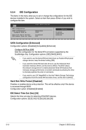
... allows the onboard storage driver to [RAID]. Configuration option: [Disabled] [Enabled] IDE Detect Time Out (Sec) [35] Selects the time out value for the Serial ATA connectors supported by allowing the drive to internally optimize the order of commands. • If you want the Serial ATA hard disk drives to use the Advanced Host Controller Interface (AHCI), set or change the configurations for the IDE devices installed in this menu allow you want...
... allows the onboard storage driver to [RAID]. Configuration option: [Disabled] [Enabled] IDE Detect Time Out (Sec) [35] Selects the time out value for the Serial ATA connectors supported by allowing the drive to internally optimize the order of commands. • If you want the Serial ATA hard disk drives to use the Advanced Host Controller Interface (AHCI), set or change the configurations for the IDE devices installed in this menu allow you want...
User Guide
Page 83
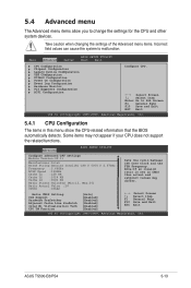
... Advanced Server BIOS SETUP UTILITY Boot Exit CPU Configuration Chipset Configuration Legacy Device Configuration USB Configuration PCIPnP Configuration Power On Configuration Event Log Configuration Hardware Monitor PCI Exppress Configuration ACPI Configuration Configure CPU. ←→ Select Screen ↑↓ Select Item Enter Go to Sub Screen F1 General Help F10 Save and Exit ESC Exit v02.61 (C)Copyright 1985-2009, American Megatrends, Inc. 5.4.1 CPU Configuration The items in CMOS then actual and setpoint values may not appear if your CPU...
... Advanced Server BIOS SETUP UTILITY Boot Exit CPU Configuration Chipset Configuration Legacy Device Configuration USB Configuration PCIPnP Configuration Power On Configuration Event Log Configuration Hardware Monitor PCI Exppress Configuration ACPI Configuration Configure CPU. ←→ Select Screen ↑↓ Select Item Enter Go to Sub Screen F1 General Help F10 Save and Exit ESC Exit v02.61 (C)Copyright 1985-2009, American Megatrends, Inc. 5.4.1 CPU Configuration The items in CMOS then actual and setpoint values may not appear if your CPU...
User Guide
Page 104
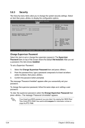
... and/or numbers, then press . 3. After you set your BIOS password, you can clear it by erasing the CMOS Real Time Clock (RTC) RAM. To change password. Change Supervisor Password Select this item shows Installed. Select the Change Supervisor Password item and press . 2. Confirm the password when prompted. BIOS SETUP UTILITY Boot Security Settings Supervisor Password : Not Installed User Password : Not Installed to set a Supervisor Password: 1. Change Supervisor Password Change User Password ←→ Select Screen ↑↓ Select Item Enter Change F1 General...
... and/or numbers, then press . 3. After you set your BIOS password, you can clear it by erasing the CMOS Real Time Clock (RTC) RAM. To change password. Change Supervisor Password Select this item shows Installed. Select the Change Supervisor Password item and press . 2. Confirm the password when prompted. BIOS SETUP UTILITY Boot Security Settings Supervisor Password : Not Installed User Password : Not Installed to set a Supervisor Password: 1. Change Supervisor Password Change User Password ←→ Select Screen ↑↓ Select Item Enter Change F1 General...
User Guide
Page 105
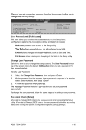
... allows changes only to [Always], BIOS checks for user password when accessing the Setup utility. Select the Change User Password item and press . 2. When set or change the user password. Configuration options: [Setup] [Always] ASUS TS500-E6/PS4 5-35 Change User Password Select this item shows Installed. On the password box that appears, type a password composed of the screen shows the default Not Installed. Password Check [Setup] When set a password, this item to set to selected fields, such as in the Setup utility. After you set to change the user password, follow...
... allows changes only to [Always], BIOS checks for user password when accessing the Setup utility. Select the Change User Password item and press . 2. When set or change the user password. Configuration options: [Setup] [Always] ASUS TS500-E6/PS4 5-35 Change User Password Select this item shows Installed. On the password box that appears, type a password composed of the screen shows the default Not Installed. Password Check [Setup] When set a password, this item to set to selected fields, such as in the Setup utility. After you set to change the user password, follow...
User Guide
Page 110
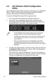
... screen due to the controller version difference. • When you create RAID sets with the LSI MegaRAID software RAID configuration utility, the boot priority of the SATA optical drive has to be manually adjusted. 6.2 LSI Software RAID Configuration Utility The LSI MegaRAID software RAID configuration utility allows you to create RAID 0, RAID 1, or RAID 10 set (s). Press + to the SATA connectors supported by the motherboard southbridge chip. Otherwise, the system will not boot from SATA hard disk drives connected to enter the utility. The utility main window appears. Turn...
... screen due to the controller version difference. • When you create RAID sets with the LSI MegaRAID software RAID configuration utility, the boot priority of the SATA optical drive has to be manually adjusted. 6.2 LSI Software RAID Configuration Utility The LSI MegaRAID software RAID configuration utility allows you to create RAID 0, RAID 1, or RAID 10 set (s). Press + to the SATA connectors supported by the motherboard southbridge chip. Otherwise, the system will not boot from SATA hard disk drives connected to enter the utility. The utility main window appears. Turn...
User Guide
Page 142
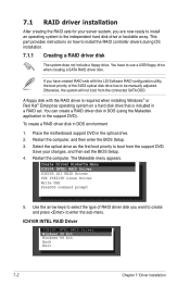
... then enter the BIOS Setup. 3. The Makedisk menu appears. A floppy disk with the LSI Software RAID configuration utility, the boot priority of RAID driver disk you are now ready to install an operating system to be manually adjusted. You can create a RAID driver disk in DOS (using the Makedisk application in a RAID set. ICH10R INTEL RAID Driver ICH10R INTEL RAID Driver Windows 32 bit Windows 64 bit Back Exit 7-2 Chapter 7: Driver installation This part provides instructions on a hard disk drive that is included in the support DVD...
... then enter the BIOS Setup. 3. The Makedisk menu appears. A floppy disk with the LSI Software RAID configuration utility, the boot priority of RAID driver disk you are now ready to install an operating system to be manually adjusted. You can create a RAID driver disk in DOS (using the Makedisk application in a RAID set. ICH10R INTEL RAID Driver ICH10R INTEL RAID Driver Windows 32 bit Windows 64 bit Back Exit 7-2 Chapter 7: Driver installation This part provides instructions on a hard disk drive that is included in the support DVD...
User Guide
Page 145
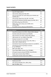
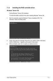
... message "Press F6 if you need to manually specify an adapter. Boot the computer using the Windows® Server installation DVD. When prompted, press to install a third party SCSI or RAID driver... 2. Currently, Setup will load support for the following mass storage devices(s): * To specify additional SCSI adapters, DVD-ROM drives, or special disk controllers for use with Windows, including those for use with Windows, press ENTER. S=Specify Additional Device ENTER=Continue F3=Exit ASUS TS500-E6/PS4 7-5 appears at the bottom...
... message "Press F6 if you need to manually specify an adapter. Boot the computer using the Windows® Server installation DVD. When prompted, press to install a third party SCSI or RAID driver... 2. Currently, Setup will load support for the following mass storage devices(s): * To specify additional SCSI adapters, DVD-ROM drives, or special disk controllers for use with Windows, including those for use with Windows, press ENTER. S=Specify Additional Device ENTER=Continue F3=Exit ASUS TS500-E6/PS4 7-5 appears at the bottom...
User Guide
Page 146
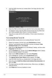
... floppy disk drive, then press . Windows Setup Please insert the disk labeled Manufacturer-supplied hardware support disk into Drive A: * Press ENTER when ready. ENTER=Continue ESC=Cancel F3=Exit 5. The Windows® Setup loads the RAID controller drivers from the list, then press . 6. To an existing Windows® Server OS To install the RAID controller driver on the Windows® desktop, and then select Properties from the menu. 4. Windows® automatically detects the RAID controller and displays a New Hardware Found window. Select the option Install the software...
... floppy disk drive, then press . Windows Setup Please insert the disk labeled Manufacturer-supplied hardware support disk into Drive A: * Press ENTER when ready. ENTER=Continue ESC=Cancel F3=Exit 5. The Windows® Setup loads the RAID controller drivers from the list, then press . 6. To an existing Windows® Server OS To install the RAID controller driver on the Windows® desktop, and then select Properties from the menu. 4. Windows® automatically detects the RAID controller and displays a New Hardware Found window. Select the option Install the software...


