TS300-E7/PS4 User Manual
Page 9
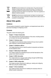
... users with at least basic knowledge of the crossed out wheeled bin indicates that you have to install the optional components and devices into the barebone server. 4. This symbol of configuring a server. About this guide Audience This user guide is intended for disposal of parts and recycling. Chapter 5: BIOS information This...
... users with at least basic knowledge of the crossed out wheeled bin indicates that you have to install the optional components and devices into the barebone server. 4. This symbol of configuring a server. About this guide Audience This user guide is intended for disposal of parts and recycling. Chapter 5: BIOS information This...
TS300-E7/PS4 User Manual
Page 13
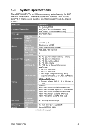
... Bays 4 x Intel® 82574L + 1 x Mgmt LAN Aspeed AST2050 16MB (continued on the next page) ASUS TS300-E7/PS4 1-3 The server supports Intel® LGA1155 Xeon® E3-1200 / Core™ i3-2100 processors, plus other latest technologies through the chipsets onboard. 1.3 System specifications The ASUS TS300-E7/PS4 is a 5U barebone server system featuring the ASUS P8B-E/4L server board.
... Bays 4 x Intel® 82574L + 1 x Mgmt LAN Aspeed AST2050 16MB (continued on the next page) ASUS TS300-E7/PS4 1-3 The server supports Intel® LGA1155 Xeon® E3-1200 / Core™ i3-2100 processors, plus other latest technologies through the chipsets onboard. 1.3 System specifications The ASUS TS300-E7/PS4 is a 5U barebone server system featuring the ASUS P8B-E/4L server board.
TS300-E7/PS4 User Manual
Page 15
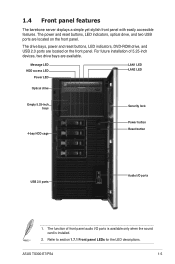
... 2.0 ports are located on the front panel. For future installation of front panel audio I /O ports 1. Refer to section 1.7.1 Front panel LEDs for the LED descriptions. ASUS TS300-E7/PS4 1-5 Message LED HDD access LED Power LED LAN1 LED LAN2 LED Optical drive Empty 5.25-inch bays 4-bay HDD cage Security lock Power button Reset..., and two USB ports are available. The function of 5.25-inch devices, two drive bays are located on the front panel. 1.4 Front panel features The barebone server displays a simple yet stylish front panel with easily accessible features.
... 2.0 ports are located on the front panel. For future installation of front panel audio I /O ports 1. Refer to section 1.7.1 Front panel LEDs for the LED descriptions. ASUS TS300-E7/PS4 1-5 Message LED HDD access LED Power LED LAN1 LED LAN2 LED Optical drive Empty 5.25-inch bays 4-bay HDD cage Security lock Power button Reset..., and two USB ports are available. The function of 5.25-inch devices, two drive bays are located on the front panel. 1.4 Front panel features The barebone server displays a simple yet stylish front panel with easily accessible features.
TS300-E7/PS4 User Manual
Page 17
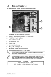
...ASUS TS300-E7/PS4 1-7 Optical drive 7. 2 x 5.25-inch drive bays 8. 4-bay HDD module (first set) 9. 4-bay HDD module (second set , hidden) Turn off the system power and detach the power supply before removing or replacing any of the USB ports on the front or rear panel if you need to any system component. The barebone... server does not include a floppy disk drive and an optical disc drive. Chassis intrusion switch 5. 1.6 Internal features The barebone server includes the basic components as shown. 1 6 7 2 10 ...
...ASUS TS300-E7/PS4 1-7 Optical drive 7. 2 x 5.25-inch drive bays 8. 4-bay HDD module (first set) 9. 4-bay HDD module (second set , hidden) Turn off the system power and detach the power supply before removing or replacing any of the USB ports on the front or rear panel if you need to any system component. The barebone... server does not include a floppy disk drive and an optical disc drive. Chassis intrusion switch 5. 1.6 Internal features The barebone server includes the basic components as shown. 1 6 7 2 10 ...
TS300-E7/PS4 User Manual
Page 22
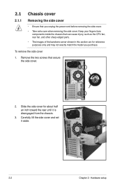
.... Remove the two screws that can cause injury, such as the CPU fan, rear fan, and other sharp-edged parts. • The images of the barebone server shown in this section are for about half an inch toward the rear until it aside. 1 2 2-2 Chapter 2: Hardware setup Carefully lift the side cover...
.... Remove the two screws that can cause injury, such as the CPU fan, rear fan, and other sharp-edged parts. • The images of the barebone server shown in this section are for about half an inch toward the rear until it aside. 1 2 2-2 Chapter 2: Hardware setup Carefully lift the side cover...
TS300-E7/PS4 User Manual
Page 47
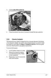
...rotating it counterclockwise with four footpads attached to the bottom of this user guide, and to reinstall the rear system fan. 2.9.2 Chassis footpads The barebone server system is shipped with a Philips (cross) screwdriver. 3. 3. Repeat step 1 and 2 to Chapter 3: Installation options of the chassis...to remove these footpads if you wish to install the system to a rack (Refer to remove the other three footpads. ASUS TS300-E7/PS4 2-27 Carefully �ta�k��e��o�ff��th��e��s�y�s�...
...rotating it counterclockwise with four footpads attached to the bottom of this user guide, and to reinstall the rear system fan. 2.9.2 Chassis footpads The barebone server system is shipped with a Philips (cross) screwdriver. 3. 3. Repeat step 1 and 2 to Chapter 3: Installation options of the chassis...to remove these footpads if you wish to install the system to a rack (Refer to remove the other three footpads. ASUS TS300-E7/PS4 2-27 Carefully �ta�k��e��o�ff��th��e��s�y�s�...
TS300-E7/PS4 User Manual
Page 49
Installation options Chapter 3 This chapter describes how to install the optional components and devices into the barebone server. ASUS TS300-E7/PS4
Installation options Chapter 3 This chapter describes how to install the optional components and devices into the barebone server. ASUS TS300-E7/PS4
TS300-E7/PS4 User Manual
Page 50
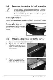
... performance. Align the screw holes on removing the footpads. Removing the footpads Refer to section 2.9.2 Chassis footpads for the optional configurations described in the standard barebone system package. Slide out the inner rail from the chassis. 3.2 Attaching the inner rail to the server 1. Removing the top cover Unscrew and slide the...
... performance. Align the screw holes on removing the footpads. Removing the footpads Refer to section 2.9.2 Chassis footpads for the optional configurations described in the standard barebone system package. Slide out the inner rail from the chassis. 3.2 Attaching the inner rail to the server 1. Removing the top cover Unscrew and slide the...