User Manual
Page 13
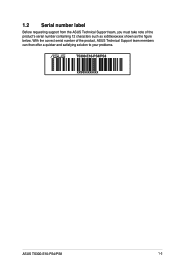
1.2 Serial number label Before requesting support from the ASUS Technical Support team, you must take note of the product, ASUS Technical Support team members can then offer a quicker and satisfying solution to your problems. TS300-E10-PS4/PS8 xxS0xxxxxxxx ASUS TS300-E10-PS4/PS8 1-3 With the correct serial number of the product's serial number containing 12 characters such as xxS0xxxxxxxx shown as the figure below.
1.2 Serial number label Before requesting support from the ASUS Technical Support team, you must take note of the product, ASUS Technical Support team members can then offer a quicker and satisfying solution to your problems. TS300-E10-PS4/PS8 xxS0xxxxxxxx ASUS TS300-E10-PS4/PS8 1-3 With the correct serial number of the product's serial number containing 12 characters such as xxS0xxxxxxxx shown as the figure below.
User Manual
Page 14
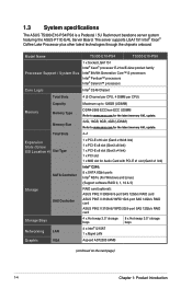
Memory Size 32G, 16GB, 8GB, 4GB (UDIMM) Refer to www.asus.com for the latest memory AVL update. Model Name Processor Support / System Bus TS300-E10-PS4 TS300-E10-PS8 1 x Socket LGA1151 Intel® Xeon® processor E-21xx/E-22xx product family Intel® 8th/9th Generation Core™ i3 processors Intel...Product Introduction The server supports LGA1151 Intel® Xeon® Coffee Lake Processor plus other latest technologies through the chipsets onboard. 1.3 System specifications The ASUS TS300-E10-PS4/PS8 is a Pedestal / 5U Rackmount barebone server system featuring the...
Memory Size 32G, 16GB, 8GB, 4GB (UDIMM) Refer to www.asus.com for the latest memory AVL update. Model Name Processor Support / System Bus TS300-E10-PS4 TS300-E10-PS8 1 x Socket LGA1151 Intel® Xeon® processor E-21xx/E-22xx product family Intel® 8th/9th Generation Core™ i3 processors Intel...Product Introduction The server supports LGA1151 Intel® Xeon® Coffee Lake Processor plus other latest technologies through the chipsets onboard. 1.3 System specifications The ASUS TS300-E10-PS4/PS8 is a Pedestal / 5U Rackmount barebone server system featuring the...
User Manual
Page 15
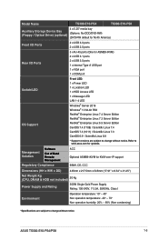
Model Name TS300-E10-PS4 TS300-E10-PS8 4 x 5.25" media bay Auxiliary Storage Device Bay (Floppy / Optical Drive) (optional) (Options: No ODD/DVD-RW) (DVD-RW default for North America) Front I/O Ports 2 x ...; ~ 40° Non operation temperature: -40° ~ 70° Non operation humidity: 20% ~ 90% (Non condensing) *Specifications are subject to change without notice. ASUS TS300-E10-PS4/PS8 1-5 Refer to www.asus.com for ASMB9-iKVM) 2 x USB 3.1 ports 2 x USB 3.0 ports 1 x internal Type A USB port 1 x VGA port 1 x COM port Switch/LED OS Support Front LED: 1 x Power...
Model Name TS300-E10-PS4 TS300-E10-PS8 4 x 5.25" media bay Auxiliary Storage Device Bay (Floppy / Optical Drive) (optional) (Options: No ODD/DVD-RW) (DVD-RW default for North America) Front I/O Ports 2 x ...; ~ 40° Non operation temperature: -40° ~ 70° Non operation humidity: 20% ~ 90% (Non condensing) *Specifications are subject to change without notice. ASUS TS300-E10-PS4/PS8 1-5 Refer to www.asus.com for ASMB9-iKVM) 2 x USB 3.1 ports 2 x USB 3.0 ports 1 x internal Type A USB port 1 x VGA port 1 x COM port Switch/LED OS Support Front LED: 1 x Power...
User Manual
Page 17
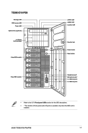
ASUS TS300-E10-PS4/PS8 LAN port 1 1-7 TS300-E10-PS8 Message LED HDD access LED Power LED Optical drive (optional) 2 x Empty 5.25-inch bays 1 2 4-bay HDD module 4-bay HDD module LAN1/3 LED LAN2/4 LED Location LED Security lock Power button Reset button Headphone jack* Microphone jack* 2 x USB 2.0 ports 2 x USB 3.0 ports • Refer to the 1.7.1 Front panel LEDs section for the LED descriptions. • * The function of front panel audio I/O ports is available only when the MIO card is installed.
ASUS TS300-E10-PS4/PS8 LAN port 1 1-7 TS300-E10-PS8 Message LED HDD access LED Power LED Optical drive (optional) 2 x Empty 5.25-inch bays 1 2 4-bay HDD module 4-bay HDD module LAN1/3 LED LAN2/4 LED Location LED Security lock Power button Reset button Headphone jack* Microphone jack* 2 x USB 2.0 ports 2 x USB 3.0 ports • Refer to the 1.7.1 Front panel LEDs section for the LED descriptions. • * The function of front panel audio I/O ports is available only when the MIO card is installed.
User Manual
Page 19
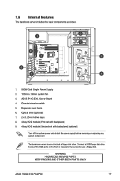
... include a floppy disk drive. WARNING HAZARDOUS MOVING PARTS KEEP FINGERS AND OTHER BODY PARTS AWAY ASUS TS300-E10-PS4/PS8 1-9 1.6 Internal features The barebone server includes the basic components as shown. 1. 500W Gold Single Power Supply 2. 120mm x 38mm system fan 3. ASUS P11C-E/4L Server Board 4. Optical drive (optional) 7. 2 x 5.25-inch drive bays 8. 4-bay HDD module...
... include a floppy disk drive. WARNING HAZARDOUS MOVING PARTS KEEP FINGERS AND OTHER BODY PARTS AWAY ASUS TS300-E10-PS4/PS8 1-9 1.6 Internal features The barebone server includes the basic components as shown. 1. 500W Gold Single Power Supply 2. 120mm x 38mm system fan 3. ASUS P11C-E/4L Server Board 4. Optical drive (optional) 7. 2 x 5.25-inch drive bays 8. 4-bay HDD module...
User Manual
Page 21
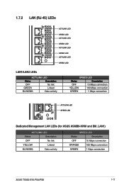
... 100 Mbps connection GREEN 1 Gbps connection ACT/LINK LED SPEED LED Dedicated Management LAN LEDs (for ASUS ASMB9-iKVM and DM_LAN1) ACT/LINK LED Status Description OFF No link YELLOW Linked BLINKING Data activity SPEED LED Status Description OFF 10 Mbps connection ORANGE 100 Mbps connection GREEN 1 Gbps connection ASUS TS300-E10-PS4/PS8 1-11
... 100 Mbps connection GREEN 1 Gbps connection ACT/LINK LED SPEED LED Dedicated Management LAN LEDs (for ASUS ASMB9-iKVM and DM_LAN1) ACT/LINK LED Status Description OFF No link YELLOW Linked BLINKING Data activity SPEED LED Status Description OFF 10 Mbps connection ORANGE 100 Mbps connection GREEN 1 Gbps connection ASUS TS300-E10-PS4/PS8 1-11
User Manual
Page 24
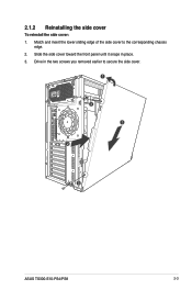
Slide the side cover toward the front panel until it snaps in the two screws you removed earlier to the corresponding chassis edge. 2. Match and insert the lower sliding edge of the side cover to secure the side cover. 1 3 1 2 3 ASUS TS300-E10-PS4/PS8 2-3 2.1.2 Reinstalling the side cover To reinstall the side cover: 1. Drive in place. 3.
Slide the side cover toward the front panel until it snaps in the two screws you removed earlier to the corresponding chassis edge. 2. Match and insert the lower sliding edge of the side cover to secure the side cover. 1 3 1 2 3 ASUS TS300-E10-PS4/PS8 2-3 2.1.2 Reinstalling the side cover To reinstall the side cover: 1. Drive in place. 3.
User Manual
Page 26
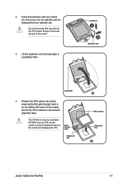
... notches to the right (B) until the load plate is on the socket and damaging the CPU. Gold triangle mark Alignment key CPU notches Alignment key ASUS TS300-E10-PS4/PS8 2-5 DO NOT force the CPU into the socket to prevent bending the pins on the bottom-left corner of the socket. 3. Do not remove...
... notches to the right (B) until the load plate is on the socket and damaging the CPU. Gold triangle mark Alignment key CPU notches Alignment key ASUS TS300-E10-PS4/PS8 2-5 DO NOT force the CPU into the socket to prevent bending the pins on the bottom-left corner of the socket. 3. Do not remove...
User Manual
Page 28
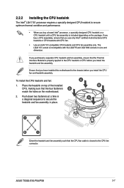
... size and dimension. If you purchased a separate CPU heatsink and fan assembly, ensure that the Thermal Interface Material is closest to the CPU fan connector. ASUS TS300-E10-PS4/PS8 2-7 Ensure that you have installed the motherboard to the chassis before you install the heatsink and fan assembly. Orient the heatsink and fan assembly...
... size and dimension. If you purchased a separate CPU heatsink and fan assembly, ensure that the Thermal Interface Material is closest to the CPU fan connector. ASUS TS300-E10-PS4/PS8 2-7 Ensure that you have installed the motherboard to the chassis before you install the heatsink and fan assembly. Orient the heatsink and fan assembly...
User Manual
Page 30
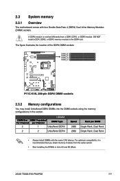
... same vendor. • Start installing the DIMMs in this section. A DDR4 module is recommended that you obtain memory modules from a DDR, DDR2, or DDR3 module. ASUS TS300-E10-PS4/PS8 2-9 UDIMM DIMM Slot DIMM Populated Per Channel per Channel DIMM Type 2 1 Unbuffered DDR4 2 2 Unbuffered DDR4 Speed 2666 2666 Rank per DIMM Single Rank, Dual...
... same vendor. • Start installing the DIMMs in this section. A DDR4 module is recommended that you obtain memory modules from a DDR, DDR2, or DDR3 module. ASUS TS300-E10-PS4/PS8 2-9 UDIMM DIMM Slot DIMM Populated Per Channel per Channel DIMM Type 2 1 Unbuffered DDR4 2 2 Unbuffered DDR4 Speed 2666 2666 Rank per DIMM Single Rank, Dual...
User Manual
Page 32
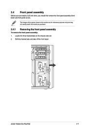
Shift the hooked tabs and take off the front bezel. Locate the three hooked tabs on the chassis side rail. 2. The images of the system shown in this section are for reference purposes only and may not exactly match the model you should first remove the front panel assembly (front bezel and front panel cover). ASUS TS300-E10-PS4/PS8 2-11 2.4 Front panel assembly Before you can install a 5.25-inch drive, you purchase. 2.4.1 Removing the front panel assembly To remove the front panel assembly: 1.
Shift the hooked tabs and take off the front bezel. Locate the three hooked tabs on the chassis side rail. 2. The images of the system shown in this section are for reference purposes only and may not exactly match the model you should first remove the front panel assembly (front bezel and front panel cover). ASUS TS300-E10-PS4/PS8 2-11 2.4 Front panel assembly Before you can install a 5.25-inch drive, you purchase. 2.4.1 Removing the front panel assembly To remove the front panel assembly: 1.
User Manual
Page 34
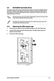
... of HDD module cage you purchase. 2.5.1 Removing the HDD module cage 1. Disconnect all the cables from the SATA/SAS backplane on the HDD module cage. 2. ASUS TS300-E10-PS4/PS8 2-13 The images of the chassis. 3. The HDD module cage will be pushed out of the system shown in this section are for mounting...
... of HDD module cage you purchase. 2.5.1 Removing the HDD module cage 1. Disconnect all the cables from the SATA/SAS backplane on the HDD module cage. 2. ASUS TS300-E10-PS4/PS8 2-13 The images of the chassis. 3. The HDD module cage will be pushed out of the system shown in this section are for mounting...

User Manual
Page 36
... on the backplane. 4. Disconnect all hot-swap HDD trays from the chassis. 2. Firmly hold the backplane, and turn it in the direction of the arrow. 5. ASUS TS300-E10-PS4/PS8 2-15 Remove the backplane from the SATA/ SAS backplane. 3. Release a drive tray by pushing the spring lock to the right, and then pulling the...
... on the backplane. 4. Disconnect all hot-swap HDD trays from the chassis. 2. Firmly hold the backplane, and turn it in the direction of the arrow. 5. ASUS TS300-E10-PS4/PS8 2-15 Remove the backplane from the SATA/ SAS backplane. 3. Release a drive tray by pushing the spring lock to the right, and then pulling the...
User Manual
Page 38
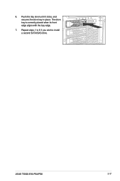
Repeat steps 1 to 6 if you wish to install a second SATA/SAS drive. The drive tray is correctly placed when its front edge aligns with the bay edge. 7. ASUS TS300-E10-PS4/PS8 2-17 6. Push the tray lever until it clicks, and secures the drive tray in place.
Repeat steps 1 to 6 if you wish to install a second SATA/SAS drive. The drive tray is correctly placed when its front edge aligns with the bay edge. 7. ASUS TS300-E10-PS4/PS8 2-17 6. Push the tray lever until it clicks, and secures the drive tray in place.
User Manual
Page 40
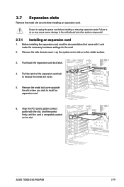
... settings for the the documentation card. 4 that c5ame with the slot, and then press firmly until the card is completely seated on a flat, stable surface. 3. ASUS TS300-E10-PS4/PS8 2-19 Pull the latch of the expansion card lock 3 to the motherboard and other system components! 2.7.1 Installing an expansion card 1. 2.7 Expansion slots Remove the...
... settings for the the documentation card. 4 that c5ame with the slot, and then press firmly until the card is completely seated on a flat, stable surface. 3. ASUS TS300-E10-PS4/PS8 2-19 Pull the latch of the expansion card lock 3 to the motherboard and other system components! 2.7.1 Installing an expansion card 1. 2.7 Expansion slots Remove the...
User Manual
Page 42
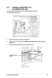
2.7.2 Installing an ASUS PIKE II card (for TS300-E10-PS4 only) You can install an ASUS PIKE II card on the provided PCI-E slot onboard. Connect the mini-SAS HD cable to install your ASUS PIKE II card. 3. Follow steps 3 to 7 in section 2.7.1 Installing an expansion card to the ASUS PIKE II card. Remove the default cable from the motherboard. 2. connect to ASUS PIKE II connector 1 ASUS TS300-E10-PS4/PS8 2-21 To install an ASUS PIKE II card: 1.
2.7.2 Installing an ASUS PIKE II card (for TS300-E10-PS4 only) You can install an ASUS PIKE II card on the provided PCI-E slot onboard. Connect the mini-SAS HD cable to install your ASUS PIKE II card. 3. Follow steps 3 to 7 in section 2.7.1 Installing an expansion card to the ASUS PIKE II card. Remove the default cable from the motherboard. 2. connect to ASUS PIKE II connector 1 ASUS TS300-E10-PS4/PS8 2-21 To install an ASUS PIKE II card: 1.
User Manual
Page 44
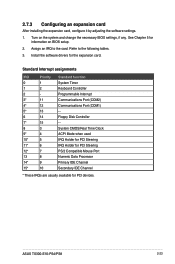
... change the necessary BIOS settings, if any. Standard Interrupt assignments IRQ Priority Standard function 0 1 System Timer 1 2 Keyboard Controller 2 - Install the software drivers for PCI devices. ASUS TS300-E10-PS4/PS8 2-23 Turn on BIOS setup. 2. Refer to the card. Assign an IRQ to the following tables. 3. 2.7.3 Configuring an expansion card After installing the expansion...
... change the necessary BIOS settings, if any. Standard Interrupt assignments IRQ Priority Standard function 0 1 System Timer 1 2 Keyboard Controller 2 - Install the software drivers for PCI devices. ASUS TS300-E10-PS4/PS8 2-23 Turn on BIOS setup. 2. Refer to the card. Assign an IRQ to the following tables. 3. 2.7.3 Configuring an expansion card After installing the expansion...
User Manual
Page 46
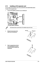
The illustrations below vary with models. 2.7.4 Installing an M.2 expansion card You can install an M.2 expansion card on your M.2 card, then secure the stand to the motherboard. Top screw Stand screw 3. ASUS TS300-E10-PS4/PS8 2-25 Remove the top screw and the stand from the motherboard. Locate the M.2 (NGFF) connectors on the provided M.2 socket (labeled M2) onboard. The installation steps are the same. 2. Select an appropriate screw hole on the motherboard for your motherboard. To install an M.2 expansion card: 1.
The illustrations below vary with models. 2.7.4 Installing an M.2 expansion card You can install an M.2 expansion card on your M.2 card, then secure the stand to the motherboard. Top screw Stand screw 3. ASUS TS300-E10-PS4/PS8 2-25 Remove the top screw and the stand from the motherboard. Locate the M.2 (NGFF) connectors on the provided M.2 socket (labeled M2) onboard. The installation steps are the same. 2. Select an appropriate screw hole on the motherboard for your motherboard. To install an M.2 expansion card: 1.
User Manual
Page 48
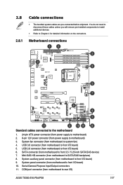
... motherboard to system fan) 4. Serial General Purpose Input/Output connectors 11. COM port connector (from motherboard to rear I /O board) 6. USB 2.0 connector (from motherboard to front I /O) ASUS TS300-E10-PS4/PS8 2-27 System panel connector (from motherboard to front 3.5 / 5.25-inch SATA/SAS device) 7. System fan connector (from motherboard to front I /O board) 10. Mini-SAS...
... motherboard to system fan) 4. Serial General Purpose Input/Output connectors 11. COM port connector (from motherboard to rear I /O board) 6. USB 2.0 connector (from motherboard to front I /O) ASUS TS300-E10-PS4/PS8 2-27 System panel connector (from motherboard to front 3.5 / 5.25-inch SATA/SAS device) 7. System fan connector (from motherboard to front I /O board) 10. Mini-SAS...
User Manual
Page 50
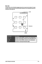
PWR1 MSAS_HD1 Connectors MSAS_HD1 BPSMB1 PWR1 BPSMB1 Description Connects to SATA SGPIO1 connector on the ASUS PIKE II card. This side includes the power connectors and SATA/SAS interfaces for the motherboard Serial ATA connectors or the SAS card. Back side The back side of the power supply ASUS TS300-E10-PS4/PS8 2-29 Connects to AUX_PANEL1 connector on the motherboard Connects to SATA/SAS connectors on the motherboard or connects to 4-pin plug of the SATA/SAS backplane faces the rear panel when installed.
PWR1 MSAS_HD1 Connectors MSAS_HD1 BPSMB1 PWR1 BPSMB1 Description Connects to SATA SGPIO1 connector on the ASUS PIKE II card. This side includes the power connectors and SATA/SAS interfaces for the motherboard Serial ATA connectors or the SAS card. Back side The back side of the power supply ASUS TS300-E10-PS4/PS8 2-29 Connects to AUX_PANEL1 connector on the motherboard Connects to SATA/SAS connectors on the motherboard or connects to 4-pin plug of the SATA/SAS backplane faces the rear panel when installed.


