T2-PE1 English User Manual E2151
Page 3
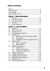
... 1-4 1.4 Rear panel 1-5 1.5 Internal components 1-7 Chapter 2: Basic Installation 2.1 Preparation 2-2 2.2 Before you proceed 2-2 2.3 Removing the cover 2-3 2.4 Removing the power supply unit 2-4 2.5 Installing a CPU 2-5 2.5.1 Removing the CPU fan and heatsink assembly ....... 2-5 2.5.2 CPU installation 2-6 2.5.3 Reinstalling the CPU fan and heatsink assembly ..... 2-9 2.6 Installing a DIMM 2-10 2.6.1 Memory configurations 2-10 2.6.2 DIMM installation 2-12 2.7 Installing an expansion card 2-13 2.7.1 Expansion slots 2-13...
... 1-4 1.4 Rear panel 1-5 1.5 Internal components 1-7 Chapter 2: Basic Installation 2.1 Preparation 2-2 2.2 Before you proceed 2-2 2.3 Removing the cover 2-3 2.4 Removing the power supply unit 2-4 2.5 Installing a CPU 2-5 2.5.1 Removing the CPU fan and heatsink assembly ....... 2-5 2.5.2 CPU installation 2-6 2.5.3 Reinstalling the CPU fan and heatsink assembly ..... 2-9 2.6 Installing a DIMM 2-10 2.6.1 Memory configurations 2-10 2.6.2 DIMM installation 2-12 2.7 Installing an expansion card 2-13 2.7.1 Expansion slots 2-13...
T2-PE1 English User Manual E2151
Page 10
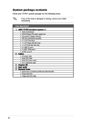
... cable 3 . System package contents Check your T2-PE1 system package for the following items. If any of the items is damaged or missing, contact your retailer immediately. User guide 5 . P E 1 b a r e b o n e s y s t e m with • ASUS motherboard • 250 W Passive PFC power supply... unit • PCI Express™ Gigabit LAN port • CPU fan and heatsink assembly • 2 x 5.25" drive bays • 1 x 3.5" floppy disk drive bay • 1 x...
... cable 3 . System package contents Check your T2-PE1 system package for the following items. If any of the items is damaged or missing, contact your retailer immediately. User guide 5 . P E 1 b a r e b o n e s y s t e m with • ASUS motherboard • 250 W Passive PFC power supply... unit • PCI Express™ Gigabit LAN port • CPU fan and heatsink assembly • 2 x 5.25" drive bays • 1 x 3.5" floppy disk drive bay • 1 x...
T2-PE1 English User Manual E2151
Page 20
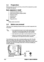
... proceed, make sure that the standby power LED is ON, in sleep mode or in soft-off mode, and not powered OFF. Central processing unit (CPU) 2. Basic components to avoid damaging them . • Whenever you uninstall any system component. ® Onboard LED 2-2 SB_PWR ON Standby Power OFF Powered Off Chapter 2: Basic...
... proceed, make sure that the standby power LED is ON, in sleep mode or in soft-off mode, and not powered OFF. Central processing unit (CPU) 2. Basic components to avoid damaging them . • Whenever you uninstall any system component. ® Onboard LED 2-2 SB_PWR ON Standby Power OFF Powered Off Chapter 2: Basic...
T2-PE1 English User Manual E2151
Page 22
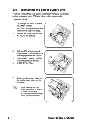
... hold or support it firmly. 2.4 Removing the power supply unit You must remove the power supply unit (PSU) before you can install a central processing unit( CPU) and other system components. 7 7 7 2-4 Chapter 2: Basic installation To remove the PSU: 1. Disconnect the optical drive and floppy disk drive power plugs. 3. When removing the PSU...
... hold or support it firmly. 2.4 Removing the power supply unit You must remove the power supply unit (PSU) before you can install a central processing unit( CPU) and other system components. 7 7 7 2-4 Chapter 2: Basic installation To remove the PSU: 1. Disconnect the optical drive and floppy disk drive power plugs. 3. When removing the PSU...
T2-PE1 English User Manual E2151
Page 23
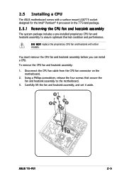
...to ensure optimum thermal condition and performance. To remove the CPU fan and heatsink assembly: 1. Carefully lift the fan and heatsink assembly, and set it aside. 2 2 2 2 1 ASUS T2-PE1 2-5 D O N O T replace the proprietary CPU fan and heatsink with a surface mount LGA775 socket designed for... the Intel® Pentium® 4 processor in the 775-land package. 2.5.1 Removing the CPU fan and heatsink assembly The system package includes a...
...to ensure optimum thermal condition and performance. To remove the CPU fan and heatsink assembly: 1. Carefully lift the fan and heatsink assembly, and set it aside. 2 2 2 2 1 ASUS T2-PE1 2-5 D O N O T replace the proprietary CPU fan and heatsink with a surface mount LGA775 socket designed for... the Intel® Pentium® 4 processor in the 775-land package. 2.5.1 Removing the CPU fan and heatsink assembly The system package includes a...
T2-PE1 English User Manual E2151
Page 24
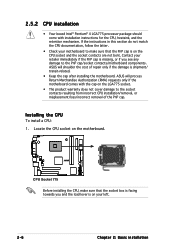
... to the PnP cap/socket contacts/motherboard components. ASUS will shoulder the cost of the PnP cap. Contact your retailer immediately if the PnP cap is shipment/ transit-related. • Keep the cap after installing the motherboard. 2.5.2 CPU installation • Your boxed Intel® Pentium®... is missing, or if you and the load lever is on the CPU socket and the socket contacts are not bent. ASUS will process Return Merchandise Authorization (RMA) requests only if the motherboard comes with installation instructions for the CPU, heatsink, and the retention mechanism.
... to the PnP cap/socket contacts/motherboard components. ASUS will shoulder the cost of the PnP cap. Contact your retailer immediately if the PnP cap is shipment/ transit-related. • Keep the cap after installing the motherboard. 2.5.2 CPU installation • Your boxed Intel® Pentium®... is missing, or if you and the load lever is on the CPU socket and the socket contacts are not bent. ASUS will process Return Merchandise Authorization (RMA) requests only if the motherboard comes with installation instructions for the CPU, heatsink, and the retention mechanism.
T2-PE1 English User Manual E2151
Page 25
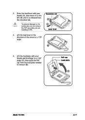
To prevent damage to a 135º angle. Retention tab A B Load lever 3 4. PnP cap Load plate B A ASUS T2-PE1 2-7 Lift the load plate with your thumb and forefinger to remove (B). 2. Press the load lever with your thumb (A), then move it to the left (B) until it is released from the load plate window to a 100º angle (A), then push the PnP cap from the retention tab. Lift the load lever in the direction of the arrow to the socket pins, do not remove the PnP cap unless you are installing a CPU. 3.
To prevent damage to a 135º angle. Retention tab A B Load lever 3 4. PnP cap Load plate B A ASUS T2-PE1 2-7 Lift the load plate with your thumb and forefinger to remove (B). 2. Press the load lever with your thumb (A), then move it to the left (B) until it is released from the load plate window to a 100º angle (A), then push the PnP cap from the retention tab. Lift the load lever in the direction of the arrow to the socket pins, do not remove the PnP cap unless you are installing a CPU. 3.
T2-PE1 English User Manual E2151
Page 26
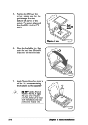
... seek professional medical help. 2-8 Chapter 2: Basic installation If it gets into your eyes or touches your skin, make sure to wash it A snaps into the CPU notch. B 7. Position the CPU over the socket, making sure that the gold triangle is on the...
... seek professional medical help. 2-8 Chapter 2: Basic installation If it gets into your eyes or touches your skin, make sure to wash it A snaps into the CPU notch. B 7. Position the CPU over the socket, making sure that the gold triangle is on the...
T2-PE1 English User Manual E2151
Page 27
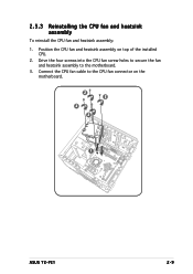
2.5.3 Reinstalling the CPU fan and heatsink assembly To reinstall the CPU fan and heatsink assembly: 1. Connect the CPU fan cable to the motherboard. 3. Position the CPU fan and heatsink assembly on the motherboard. 2 2 2 2 1 ASUS T2-PE1 2-9 Drive the four screws into the CPU fan screw holes to secure the fan and heatsink assembly to the CPU fan connector on top of the installed CPU. 2.
2.5.3 Reinstalling the CPU fan and heatsink assembly To reinstall the CPU fan and heatsink assembly: 1. Connect the CPU fan cable to the motherboard. 3. Position the CPU fan and heatsink assembly on the motherboard. 2 2 2 2 1 ASUS T2-PE1 2-9 Drive the four screws into the CPU fan screw holes to secure the fan and heatsink assembly to the CPU fan connector on top of the installed CPU. 2.
T2-PE1 English User Manual E2151
Page 41
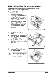
... the PSU cables do not interfere with the screw you removed earlier. Position the PSU over the chassis. 4. Secure the PSU with the CPU and/or chassis fans. 4 5 6 3 7 ASUS T2-PE1 2-23 Connect the two 4-pin 12 V power plugs to the EATXPWR connector on the motherboard. To reinstall the PSU: 1. See page 4-6 for the...
... the PSU cables do not interfere with the screw you removed earlier. Position the PSU over the chassis. 4. Secure the PSU with the CPU and/or chassis fans. 4 5 6 3 7 ASUS T2-PE1 2-23 Connect the two 4-pin 12 V power plugs to the EATXPWR connector on the motherboard. To reinstall the PSU: 1. See page 4-6 for the...
T2-PE1 English User Manual E2151
Page 48
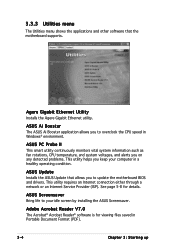
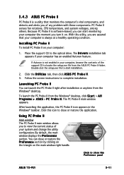
...applications and other software that allows you to update the motherboard BIOS and drivers. ASUS PC Probe II This smart utility continuously monitors vital system information such as fan rotations, CPU temperature, and system voltages, and alerts you on any detected problems. This ... Adobe Acrobat Reader V7.0 The Acrobat® Acrobat Reader® software is for details. ASUS Update Installs the ASUS Update that the motherboard supports. ASUS Screensaver Bring life to overclock the CPU speed in Windows® environment. See page 5-8 for viewing files saved in a healthy ...
...applications and other software that allows you to update the motherboard BIOS and drivers. ASUS PC Probe II This smart utility continuously monitors vital system information such as fan rotations, CPU temperature, and system voltages, and alerts you on any detected problems. This ... Adobe Acrobat Reader V7.0 The Acrobat® Acrobat Reader® software is for details. ASUS Update Installs the ASUS Update that the motherboard supports. ASUS Screensaver Bring life to overclock the CPU speed in Windows® environment. See page 5-8 for viewing files saved in a healthy ...
T2-PE1 English User Manual E2151
Page 55
...Probe II senses fan rotations, CPU temperature, and system voltages, among others. Place the support CD to start monitoring your computer the moment you turn it on. Double-click the setup.exe file to the optical drive. Follow the screen instructions to close the Preference panel ASUS T2-PE1 3-11 By default, the main... PC Probe II Main window The PC Probe II main window allows you of the support CD to locate the setup.exe file from the ASUS PC Probe II folder. Because PC Probe II is always at a healthy operating condition. After launching the application, the PC Probe II icon appears...
...Probe II senses fan rotations, CPU temperature, and system voltages, among others. Place the support CD to start monitoring your computer the moment you turn it on. Double-click the setup.exe file to the optical drive. Follow the screen instructions to close the Preference panel ASUS T2-PE1 3-11 By default, the main... PC Probe II Main window The PC Probe II main window allows you of the support CD to locate the setup.exe file from the ASUS PC Probe II folder. Because PC Probe II is always at a healthy operating condition. After launching the application, the PC Probe II icon appears...
T2-PE1 English User Manual E2151
Page 56
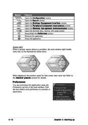
Button Function Opens the C o n f i g u r a t i o n window Opens the R e p o r t window Opens the D e s k t o p M a n a g e m e n t I n t e r f a c e window Opens the P e r i p h e r a l C o m p o n e n t I n t e r c o n n e c t window Opens the W i n d o w s M a n a g e m e n t I n s t r u m e n t a t i o n window Opens the hard disk drive, memory, CPU usage window Shows/Hides the P r e f e r e n c e section Minimizes the application Closes the application Sensor alert When a system sensor detects a problem, the main window right handle turns ...
Button Function Opens the C o n f i g u r a t i o n window Opens the R e p o r t window Opens the D e s k t o p M a n a g e m e n t I n t e r f a c e window Opens the P e r i p h e r a l C o m p o n e n t I n t e r c o n n e c t window Opens the W i n d o w s M a n a g e m e n t I n s t r u m e n t a t i o n window Opens the hard disk drive, memory, CPU usage window Shows/Hides the P r e f e r e n c e section Minimizes the application Closes the application Sensor alert When a system sensor detects a problem, the main window right handle turns ...

T2-PE1 English User Manual E2151
Page 57
... The hardware monitor panels display the current value of the S c h e m e options, then select another position from the list box. When you want to decrease value ASUS T2-PE1 3-13 Click to increase value Click to detach a monitor panel from the group, click the horseshoe magnet icon. You can now move together using the.... Click O K when finished. You can adjust the sensor threshold value in the desktop, click the arrow down button of a system sensor such as fan rotation, CPU temperature, and voltages.
... The hardware monitor panels display the current value of the S c h e m e options, then select another position from the list box. When you want to decrease value ASUS T2-PE1 3-13 Click to increase value Click to detach a monitor panel from the group, click the horseshoe magnet icon. You can now move together using the.... Click O K when finished. You can adjust the sensor threshold value in the desktop, click the arrow down button of a system sensor such as fan rotation, CPU temperature, and voltages.
T2-PE1 English User Manual E2151
Page 59
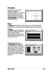
...Usage browser. The left panel of the two logical processors. CPU usage The C P U tab displays real-time CPU usage in line graph representation. Click a hard disk drive to display available information. If the CPU has an enabled Hyper-Threading, two separate line graphs display ...installed on the CPU, hard disk drive space, and memory usage. Click the plus sign (+) before the P C I I n f o r m a t i o n item to display the information on the right panel. Hard disk drive space usage The H a r d D i s k tab displays the used (blue) and the available HDD space. ASUS T2-PE1 3-15
...Usage browser. The left panel of the two logical processors. CPU usage The C P U tab displays real-time CPU usage in line graph representation. Click a hard disk drive to display available information. If the CPU has an enabled Hyper-Threading, two separate line graphs display ...installed on the CPU, hard disk drive space, and memory usage. Click the plus sign (+) before the P C I I n f o r m a t i o n item to display the information on the right panel. Hard disk drive space usage The H a r d D i s k tab displays the used (blue) and the available HDD space. ASUS T2-PE1 3-15
T2-PE1 English User Manual E2151
Page 65
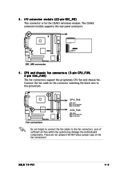
...forget to connect the fan cables to the fan connectors. The CGAEX extension module supports the rear panel serial port. These are not jumpers! ASUS T2-PE1 4-5 Lack of sufficient air flow within the system may damage the motherboard components. I/O extension module (22-pin IOC_MB) This connector is for... the CGAEX extension module. COM1 ¤ ¤ CGAEX IOC_DC IOC_MB connector 4 . CPU and chassis fan connectors (3-pin CPU_FAN, 3-pin CHA_FAN) The fan connectors support the proprietary CPU fan and chassis fan. 3 .
...forget to connect the fan cables to the fan connectors. The CGAEX extension module supports the rear panel serial port. These are not jumpers! ASUS T2-PE1 4-5 Lack of sufficient air flow within the system may damage the motherboard components. I/O extension module (22-pin IOC_MB) This connector is for... the CGAEX extension module. COM1 ¤ ¤ CGAEX IOC_DC IOC_MB connector 4 . CPU and chassis fan connectors (3-pin CPU_FAN, 3-pin CHA_FAN) The fan connectors support the proprietary CPU fan and chassis fan. 3 .
T2-PE1 English User Manual E2151
Page 87
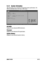
...Displays the auto-detected BIOS information. System Memory Displays the auto-detected system memory. ASUS T2-PE1 5-17 The BIOS automatically detects the items in this menu. Processor Displays the auto-detected CPU specification. 5.3.5 System Information This menu gives you an overview of the general system ...specifications. Main BIOS SETUP UTILITY AMIBIOS Version : 0023 Build Date : 08/02/05 Processor Type Speed Count : Genuine Intel (R) CPU 3.20 GHz : 3200 MHz : 1 System Memory Size : 192 MB Select Screen Select Item F1 General Help F10 Save and Exit ESC...
...Displays the auto-detected BIOS information. System Memory Displays the auto-detected system memory. ASUS T2-PE1 5-17 The BIOS automatically detects the items in this menu. Processor Displays the auto-detected CPU specification. 5.3.5 System Information This menu gives you an overview of the general system ...specifications. Main BIOS SETUP UTILITY AMIBIOS Version : 0023 Build Date : 08/02/05 Processor Type Speed Count : Genuine Intel (R) CPU 3.20 GHz : 3200 MHz : 1 System Memory Size : 192 MB Select Screen Select Item F1 General Help F10 Save and Exit ESC...
T2-PE1 English User Manual E2151
Page 88
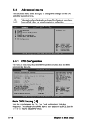
...General Help F10 Save and Exit ESC Exit v02.58 (C)Copyright 1985-2004, American Megatrends, Inc. Advanced BIOS SETUP UTILITY Configure advanced CPU Settings Manufacturer : Intel Brand String : Genuine Intel(R) CPU 3.20 GHz Frequency : 3200 MHz FSB Speed : 800 MHz Cache L1 Cache L2 Cache L3 : 16 KB : 1024 KB :... system to Subscreen Tab Select Field F1 General Help F10 Save and Exit v02.58 (C)Copyright 1985-2004, American Megatrends, Inc. 5.4.1 CPU Configuration The items in CMOS then actual and setpoint values may differ. Take caution when changing the settings of this menu show the...
...General Help F10 Save and Exit ESC Exit v02.58 (C)Copyright 1985-2004, American Megatrends, Inc. Advanced BIOS SETUP UTILITY Configure advanced CPU Settings Manufacturer : Intel Brand String : Genuine Intel(R) CPU 3.20 GHz Frequency : 3200 MHz FSB Speed : 800 MHz Cache L1 Cache L2 Cache L3 : 16 KB : 1024 KB :... system to Subscreen Tab Select Field F1 General Help F10 Save and Exit v02.58 (C)Copyright 1985-2004, American Megatrends, Inc. 5.4.1 CPU Configuration The items in CMOS then actual and setpoint values may differ. Take caution when changing the settings of this menu show the...
T2-PE1 English User Manual E2151
Page 89
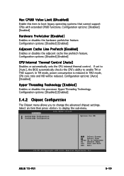
... to boot legacy operating systems that cannot support CPUs with extended CPUID functions. Configuration options: [Disabled] [Enabled] CPU Internal Thermal Control [Auto] Disables or automatically sets the CPU internal thermal control. Max CPUID Value Limit [Disabled] Enable this item to enable TM or TM2 support. Configuration options: [Disabled] [Enabled] Adjacent Cache...or disables the adjacent cache line prefetch feature. Configuration options: [Disabled] [Enabled] 5.4.2 Chipset Configuration The Chipset menu allows you to change the advanced chipset settings. ASUS T2-PE1 5-19
... to boot legacy operating systems that cannot support CPUs with extended CPUID functions. Configuration options: [Disabled] [Enabled] CPU Internal Thermal Control [Auto] Disables or automatically sets the CPU internal thermal control. Max CPUID Value Limit [Disabled] Enable this item to enable TM or TM2 support. Configuration options: [Disabled] [Enabled] Adjacent Cache...or disables the adjacent cache line prefetch feature. Configuration options: [Disabled] [Enabled] 5.4.2 Chipset Configuration The Chipset menu allows you to change the advanced chipset settings. ASUS T2-PE1 5-19
T2-PE1 English User Manual E2151
Page 95
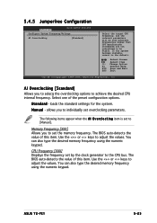
... r d - allows you to [Manual]. Memory Frequency [XXX] Allows you to achieve the desired CPU internal frequency. You can also type the desired memory frequency using the numeric keypad. ASUS T2-PE1 5-25 Change Option F1 General Help F10 Save and Exit ESC Exit v02.58 (C)Copyright 1985-2004,...Advanced BIOS SETUP UTILITY Configure System Frequency/Voltage AI Overclocking [Standard] Select the target CPU frequency, and the relevant parameters will be stable. Frequencies higher that CPU manufacturer recommends are not guaranteed to adjust the values. loads the standard settings for ...
... r d - allows you to [Manual]. Memory Frequency [XXX] Allows you to achieve the desired CPU internal frequency. You can also type the desired memory frequency using the numeric keypad. ASUS T2-PE1 5-25 Change Option F1 General Help F10 Save and Exit ESC Exit v02.58 (C)Copyright 1985-2004,...Advanced BIOS SETUP UTILITY Configure System Frequency/Voltage AI Overclocking [Standard] Select the target CPU frequency, and the relevant parameters will be stable. Frequencies higher that CPU manufacturer recommends are not guaranteed to adjust the values. loads the standard settings for ...


