T2-P User Manual
Page 10
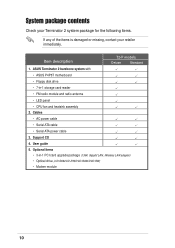
Cables • AC power cable • Serial ATA cable • Serial ATA power cable 3. ASUS Terminator 2 barebone system with • ASUS P4P8T motherboard • Floppy disk drive • 7-in -1 PCI card upgrade package (1394, Gigabit LAN, Wireless LAN adapter) • Optical drive (CD-ROM/CD-RW/... 4. Optional items • 3-in -1 storage card reader • FM radio module and radio antenna • LED panel • CPU fan and heatsink assembly 2. Item description T2-P models Deluxe Standard 1.
Cables • AC power cable • Serial ATA cable • Serial ATA power cable 3. ASUS Terminator 2 barebone system with • ASUS P4P8T motherboard • Floppy disk drive • 7-in -1 PCI card upgrade package (1394, Gigabit LAN, Wireless LAN adapter) • Optical drive (CD-ROM/CD-RW/... 4. Optional items • 3-in -1 storage card reader • FM radio module and radio antenna • LED panel • CPU fan and heatsink assembly 2. Item description T2-P models Deluxe Standard 1.
T2-P User Manual
Page 12
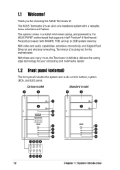
... Ethernet and wireless networking, Terminator 2 is an all-in a stylish mini-tower casing, and powered by the ASUS P4P8T motherboard that supports Intel® Pentium® 4 Northwood/ Prescott processor with a versatile home entertainment feature. Deluxe model 1 2 Standard model 1 2 3 4 9 10 MODE 5 6 7 8 11 12 13 14 MODE 3 4 5 6 7 8 15 16 17 18 12 Chapter 1: System...
... Ethernet and wireless networking, Terminator 2 is an all-in a stylish mini-tower casing, and powered by the ASUS P4P8T motherboard that supports Intel® Pentium® 4 Northwood/ Prescott processor with a versatile home entertainment feature. Deluxe model 1 2 Standard model 1 2 3 4 9 10 MODE 5 6 7 8 11 12 13 14 MODE 3 4 5 6 7 8 15 16 17 18 12 Chapter 1: System...
T2-P User Manual
Page 13
... seconds or presets a station when pressed for details. PLAY/PAUSE button ( / ). ASUS Terminator 2 barebone system 13 Power LED . When lit, this door to access the 6-in Audio DJ mode. LED panel (Deluxe models only). The audio control buttons are activated only when the system is being read...drive. 4. Press this button to FM radio mode or vice versa. 13. Power button . The following front panel buttons are available on deluxe models only. 11. The Audio DJ feature allows you eject the loading tray. 3. Mode button. In Radio mode, scans the available FM...
... seconds or presets a station when pressed for details. PLAY/PAUSE button ( / ). ASUS Terminator 2 barebone system 13 Power LED . When lit, this door to access the 6-in Audio DJ mode. LED panel (Deluxe models only). The audio control buttons are activated only when the system is being read...drive. 4. Press this button to FM radio mode or vice versa. 13. Power button . The following front panel buttons are available on deluxe models only. 11. The Audio DJ feature allows you eject the loading tray. 3. Mode button. In Radio mode, scans the available FM...
T2-P User Manual
Page 15
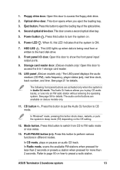
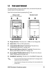
Open the front panel doors by pressing the mark. SmartMedia® card slot . ASUS Terminator 2 barebone system 15 Floppy disk drive. Memory Stick®/Memory Stick Pro™ card slot. Secure Digital™/MultimediaCard slot . 1.3 Front panel ...(internal) The optical drive(s), storage card reader slots, and several I/O ports are located inside the front panel doors. Deluxe model (with it. Optical drive. This slot is an IDE optical drive. 21. This is for a Secure Digital™/MultimediaCard storage card. 24. This ...
Open the front panel doors by pressing the mark. SmartMedia® card slot . ASUS Terminator 2 barebone system 15 Floppy disk drive. Memory Stick®/Memory Stick Pro™ card slot. Secure Digital™/MultimediaCard slot . 1.3 Front panel ...(internal) The optical drive(s), storage card reader slots, and several I/O ports are located inside the front panel doors. Deluxe model (with it. Optical drive. This slot is an IDE optical drive. 21. This is for a Secure Digital™/MultimediaCard storage card. 24. This ...

T2-P User Manual
Page 17
... connects an RJ-11 cable jack. GAME/MIDI port . This green 6-pin connector is for a PS/2 keyboard. Serial port . PS/2 mouse port . PS/2 keyboard port . ASUS Terminator 2 barebone system 17 Connect one end of an RJ-11 cable to this port and the other end to the RJ-11 wall socket... and several I/O ports that conforms with 3-in-1 PCI card upgrade) 1 2 15 3 4 5 16 6 7 8 17 9 10 18 11 12 19 13 14 20 21 22 23 24 1. Deluxe model (with serial specification. 5. This port connects an RJ-11 cable jack. Connect one end of an RJ-11 cable to this port and the...
... connects an RJ-11 cable jack. GAME/MIDI port . This green 6-pin connector is for a PS/2 keyboard. Serial port . PS/2 mouse port . PS/2 keyboard port . ASUS Terminator 2 barebone system 17 Connect one end of an RJ-11 cable to this port and the other end to the RJ-11 wall socket... and several I/O ports that conforms with 3-in-1 PCI card upgrade) 1 2 15 3 4 5 16 6 7 8 17 9 10 18 11 12 19 13 14 20 21 22 23 24 1. Deluxe model (with serial specification. 5. This port connects an RJ-11 cable jack. Connect one end of an RJ-11 cable to this port and the...
T2-P User Manual
Page 21
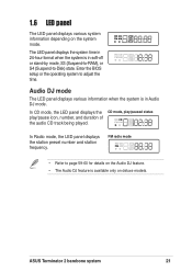
...) state. Audio DJ mode The LED panel displays various information when the system is available only on deluxe models. FM radio mode • Refer to page 59-60 for details on the system mode. ASUS Terminator 2 barebone system 21 1.6 LED panel The LED panel displays various system information depending on the Audio...
...) state. Audio DJ mode The LED panel displays various information when the system is available only on deluxe models. FM radio mode • Refer to page 59-60 for details on the system mode. ASUS Terminator 2 barebone system 21 1.6 LED panel The LED panel displays various system information depending on the Audio...
T2-P User Manual
Page 35
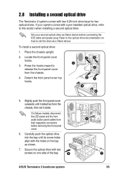
...plug. If your second optical drive as shown. 7. Secure the optical drive with two 5.25-inch drive bays for two optical drives. On Deluxe models, disconnect the LED panel and the front audio button panel cables from the chassis. 4. Refer to the optical drive documentation on one ...side of the bay. 6 5 7 ASUS Terminator 2 barebone system 35 Locate the front panel cover hooks. 3. To install a second optical drive: 1. Carefully push the optical drive into the bay...
...plug. If your second optical drive as shown. 7. Secure the optical drive with two 5.25-inch drive bays for two optical drives. On Deluxe models, disconnect the LED panel and the front audio button panel cables from the chassis. 4. Refer to the optical drive documentation on one ...side of the bay. 6 5 7 ASUS Terminator 2 barebone system 35 Locate the front panel cover hooks. 3. To install a second optical drive: 1. Carefully push the optical drive into the bay...
T2-P User Manual
Page 36
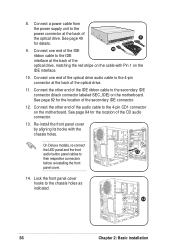
... 82 for details. 9. Connect a power cable from the power supply unit to the power connector at the back of the CD audio connector. 13. On Deluxe models, re-connect the LED panel and the front 13 audio button panel cables to the chassis holes as indicated. 14 36 Chapter 2: Basic installation...
... 82 for details. 9. Connect a power cable from the power supply unit to the power connector at the back of the CD audio connector. 13. On Deluxe models, re-connect the LED panel and the front 13 audio button panel cables to the chassis holes as indicated. 14 36 Chapter 2: Basic installation...
T2-P User Manual
Page 42
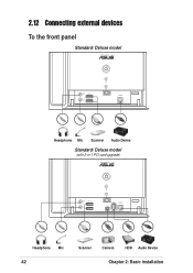
2.12 Connecting external devices To the front panel Standard/ Deluxe model Headphone Mic Scanner Audio Device Standard/ Deluxe model (with 3-in-1 PCI card upgrade) Headphone Mic 42 Scanner Camera HDD Audio Device Chapter 2: Basic installation
2.12 Connecting external devices To the front panel Standard/ Deluxe model Headphone Mic Scanner Audio Device Standard/ Deluxe model (with 3-in-1 PCI card upgrade) Headphone Mic 42 Scanner Camera HDD Audio Device Chapter 2: Basic installation
T2-P User Manual
Page 46
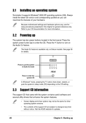
...to your hardware. Press the system power button ( ) to change at any time without notice. See page 59 for general reference only. Visit the ASUS website for more information. 3.2 Powering up The Audio DJ feature is available only on the OS setting. 3.3 Support CD information The support CD that... of your OS documentation for updates. 46 Chapter 3: Starting up The system has two power buttons located in sleep mode (S3) depending on Deluxe models. Press to put the system in Audio DJ mode MODE Press to enter the system OS In Windows® mode, pressing the button shuts...
...to your hardware. Press the system power button ( ) to change at any time without notice. See page 59 for general reference only. Visit the ASUS website for more information. 3.2 Powering up The Audio DJ feature is available only on the OS setting. 3.3 Support CD information The support CD that... of your OS documentation for updates. 46 Chapter 3: Starting up The system has two power buttons located in sleep mode (S3) depending on Deluxe models. Press to put the system in Audio DJ mode MODE Press to enter the system OS In Windows® mode, pressing the button shuts...
T2-P User Manual
Page 48
... 3: Starting up ASUS Radio Application This item installs the ASUS radio application that the motherboard supports. LifeView TV tuner allows you to tune in 1 Card Reader Driver This item installs the driver for details. This item appears only on Deluxe models. ASUS Wireless LAN Adapter ...Driver This item installs the ASUS wireless LAN driver. See page 54 for details. 3.3.3 Utilities menu The Utilities menu shows the applications...
... 3: Starting up ASUS Radio Application This item installs the ASUS radio application that the motherboard supports. LifeView TV tuner allows you to tune in 1 Card Reader Driver This item installs the driver for details. This item appears only on Deluxe models. ASUS Wireless LAN Adapter ...Driver This item installs the ASUS wireless LAN driver. See page 54 for details. 3.3.3 Utilities menu The Utilities menu shows the applications...
T2-P User Manual
Page 79
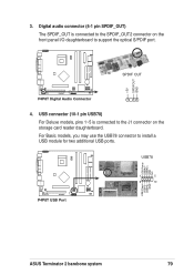
USBP3+ GND 1 5 6 10 ASUS Terminator 2 barebone system 79 USB78 USB Power USBP2- 3. USB connector (10-1 pin USB78) For Deluxe models, pins 1~5 is connected to the SPDIF_OUT2 connector on the storage card reader daughterboard. For Basic models, you may use the USB78 connector to the ...
USBP3+ GND 1 5 6 10 ASUS Terminator 2 barebone system 79 USB78 USB Power USBP2- 3. USB connector (10-1 pin USB78) For Deluxe models, pins 1~5 is connected to the SPDIF_OUT2 connector on the storage card reader daughterboard. For Basic models, you may use the USB78 connector to the ...