User Guide
Page 13
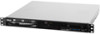
...Graphic VGA Auxiliary Storage FDD / CD / DVD Onboard I = internal A or S = hotswappable RS100-E8/PI2 1 x Socket LGA1150 Intel® Xeon® E3-1200 v3 Processor Family Intel® C224... up to two 2.5-inch SSDs. 1.3 System specifications The ASUS RS100-E8-PI2 is a 1U barebone server system featuring the ASUS P9D-M server board. Model Name Processor / System Bus Core Logic ASUS Features Smart Fan ASWM Enterprise Total Slots Memory Capacity Memory ...x 2) 1 x VGA port 2 x USB 2.0 port (Rear x2) 1 x PS/2 keyboard/mouse port (continued on the next page) ASUS RS100-E8-PI2 1-3
...Graphic VGA Auxiliary Storage FDD / CD / DVD Onboard I = internal A or S = hotswappable RS100-E8/PI2 1 x Socket LGA1150 Intel® Xeon® E3-1200 v3 Processor Family Intel® C224... up to two 2.5-inch SSDs. 1.3 System specifications The ASUS RS100-E8-PI2 is a 1U barebone server system featuring the ASUS P9D-M server board. Model Name Processor / System Bus Core Logic ASUS Features Smart Fan ASWM Enterprise Total Slots Memory Capacity Memory ...x 2) 1 x VGA port 2 x USB 2.0 port (Rear x2) 1 x PS/2 keyboard/mouse port (continued on the next page) ASUS RS100-E8-PI2 1-3
User Guide
Page 15
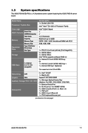
... any system component. 1.5 Rear panel features The rear panel has the AC power socket and access to section 1.7.1 Front panel LEDs for an ASUS ASMB7-iKVM controller card only. ASUS RS100-E8-PI2 1-5 Optical drive (optional) LAN1~2 LEDs Message LED HDD Access LED Power button VGA port USB 3.0 ports Reset button LED location button Asset...
... any system component. 1.5 Rear panel features The rear panel has the AC power socket and access to section 1.7.1 Front panel LEDs for an ASUS ASMB7-iKVM controller card only. ASUS RS100-E8-PI2 1-5 Optical drive (optional) LAN1~2 LEDs Message LED HDD Access LED Power button VGA port USB 3.0 ports Reset button LED location button Asset...

User Guide
Page 17
OFF Normal status. (Press the location switch again to turn off.) ASUS RS100-E8-PI2 1-7 indicates no incoming event 1. Without ASMB7-iKVM installed: CPU over-heated ON 2. 1.7 LED information 1.7.1 Front panel LEDs LAN1~2 LED Message LED HDD Access LED Power ...
OFF Normal status. (Press the location switch again to turn off.) ASUS RS100-E8-PI2 1-7 indicates no incoming event 1. Without ASMB7-iKVM installed: CPU over-heated ON 2. 1.7 LED information 1.7.1 Front panel LEDs LAN1~2 LED Message LED HDD Access LED Power ...

User Guide
Page 21
Side tabs ASUS RS100-E8-PI2 2-3 2.1.2 Reinstalling the chassis cover To reinstall the chassis cover: 1. Slide the cover toward the front until it snaps in place. Position the cover on top of the chassis with the hooks aligned to the side tabs of the chassis. 2.
Side tabs ASUS RS100-E8-PI2 2-3 2.1.2 Reinstalling the chassis cover To reinstall the chassis cover: 1. Slide the cover toward the front until it snaps in place. Position the cover on top of the chassis with the hooks aligned to the side tabs of the chassis. 2.
User Guide
Page 23
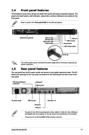
ASUS will process Return Merchandise Authorization (RMA) requests only if the motherboard comes with a surface mount LGA1150 socket designed for the Intel® Xeon® E3-... motherboard comes with the cap on the motherboard. Contact your right. ASUS will shoulder the cost of the PnP cap. 2.2.1 Installing the CPU To install the CPU: 1. Locate the CPU socket on the LGA1150 socket. • The product warranty does not cover damage to the PnP cap/socket contacts/motherboard components. ASUS RS100-E8-PI2 2-5
ASUS will process Return Merchandise Authorization (RMA) requests only if the motherboard comes with a surface mount LGA1150 socket designed for the Intel® Xeon® E3-... motherboard comes with the cap on the motherboard. Contact your right. ASUS will shoulder the cost of the PnP cap. 2.2.1 Installing the CPU To install the CPU: 1. Locate the CPU socket on the LGA1150 socket. • The product warranty does not cover damage to the PnP cap/socket contacts/motherboard components. ASUS RS100-E8-PI2 2-5

User Guide
Page 25
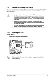
ASUS RS100-E8-PI2 2-7 Load lever Retention tab 7. Apply some Thermal Interface Material to the exposed area of the load plate slides under the retention tab to remove the ...
ASUS RS100-E8-PI2 2-7 Load lever Retention tab 7. Apply some Thermal Interface Material to the exposed area of the load plate slides under the retention tab to remove the ...

User Guide
Page 27
Locate and remove the screw for the airduct from the motherboard. 2. ASUS RS100-E8-PI2 2-9 The fastener on the airduct should align with the screwhole on the motherboard. 3. Replace the screw and secure the airduct onto the motherboard. To install the airduct: 1. Place the airduct over the heatsink.
Locate and remove the screw for the airduct from the motherboard. 2. ASUS RS100-E8-PI2 2-9 The fastener on the airduct should align with the screwhole on the motherboard. 3. Replace the screw and secure the airduct onto the motherboard. To install the airduct: 1. Place the airduct over the heatsink.
User Guide
Page 29
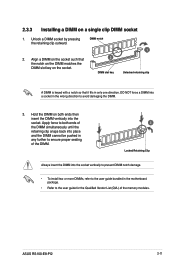
... retaining clip outward. Align a DIMM on the socket such that the notch on the DIMM matches the DIMM slot key on a single clip DIMM socket 1. ASUS RS100-E8-PI2 2-11 2.3.3 Installing a DIMM on the socket. 2 DIMM slot key 1 Unlocked retaining clip A DIMM is keyed with a notch so that it fits in the motherboard package...
... retaining clip outward. Align a DIMM on the socket such that the notch on the DIMM matches the DIMM slot key on a single clip DIMM socket 1. ASUS RS100-E8-PI2 2-11 2.3.3 Installing a DIMM on the socket. 2 DIMM slot key 1 Unlocked retaining clip A DIMM is keyed with a notch so that it fits in the motherboard package...

User Guide
Page 31
... screws. 5. Prepare a 3.5-inch Serial ATA HDD and the set aside. 4. Release the four screws that the 3.5-inch SATA HDD is seated securely in the chassis. 2. ASUS RS100-E8-PI2 HDD drive tray HDD bay 1 2-13 2.4 Hard disk drives The server chassis has two HDD bays for installing HDDs to HDD bay 1: 1. Locate the HDD...
... screws. 5. Prepare a 3.5-inch Serial ATA HDD and the set aside. 4. Release the four screws that the 3.5-inch SATA HDD is seated securely in the chassis. 2. ASUS RS100-E8-PI2 HDD drive tray HDD bay 1 2-13 2.4 Hard disk drives The server chassis has two HDD bays for installing HDDs to HDD bay 1: 1. Locate the HDD...

User Guide
Page 33
... from the 3.5-inch SATA HDD. 3. HDD drive tray HDD bay 1 4. Get one 2.5-inch SSD and orient it in the chassis. 2. SSD drive tray 2.5-inch SSD ASUS RS100-E8-PI2 2-15 Remove the HDD drive tray and 3.5-inch SATA HDD assembly. 5. Fasten the 2.5-inch SSD to HDD bay 1 and set aside. Release the four screws...
... from the 3.5-inch SATA HDD. 3. HDD drive tray HDD bay 1 4. Get one 2.5-inch SSD and orient it in the chassis. 2. SSD drive tray 2.5-inch SSD ASUS RS100-E8-PI2 2-15 Remove the HDD drive tray and 3.5-inch SATA HDD assembly. 5. Fasten the 2.5-inch SSD to HDD bay 1 and set aside. Release the four screws...
User Guide
Page 35
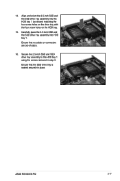
Secure the 2.5-inch SSD and SSD drive tray assembly to the HDD bay 1 using the screws removed in place. Align and orient the 2.5-inch SSD and the SSD drive tray assembly into HDD bay 1. Carefully place the 2.5-inch SSD and the SSD drive tray assembly into the HDD bay 1 (as shown) matching the four screw holes on the drive tray with the four screw holes on the HDD bay. 15. Ensure that the SSD drive tray is seated securely in step 3. Ensure that no cables or connectors are out-of-place. 16. ASUS RS100-E8-PI2 2-17 14.
Secure the 2.5-inch SSD and SSD drive tray assembly to the HDD bay 1 using the screws removed in place. Align and orient the 2.5-inch SSD and the SSD drive tray assembly into HDD bay 1. Carefully place the 2.5-inch SSD and the SSD drive tray assembly into the HDD bay 1 (as shown) matching the four screw holes on the drive tray with the four screw holes on the HDD bay. 15. Ensure that the SSD drive tray is seated securely in step 3. Ensure that no cables or connectors are out-of-place. 16. ASUS RS100-E8-PI2 2-17 14.

User Guide
Page 37
.... 1.d Remove the ODD as shown and set of screws as shown. 6. Remove the HDD drive tray. 4. Get a 3.5-inch Serial ATA HDD and the set aside. 2. ASUS RS100-E8-PI2 2-19 Use an L-type SATA connector to connect the 3.5-inch SATA HDD to the chassis. Connect a SATA signal cable and a power cable from the power...
.... 1.d Remove the ODD as shown and set of screws as shown. 6. Remove the HDD drive tray. 4. Get a 3.5-inch Serial ATA HDD and the set aside. 2. ASUS RS100-E8-PI2 2-19 Use an L-type SATA connector to connect the 3.5-inch SATA HDD to the chassis. Connect a SATA signal cable and a power cable from the power...

User Guide
Page 39
... an expansion card To install an expansion card: 1. Remove the screw to release the metal slot cover from the PCI Express slot on the motherboard. 2. ASUS RS100-E8-PI2 2-21
... an expansion card To install an expansion card: 1. Remove the screw to release the metal slot cover from the PCI Express slot on the motherboard. 2. ASUS RS100-E8-PI2 2-21

User Guide
Page 41
.../2 Compatible Mouse Port 13 8 Numeric Data Processor 14* 9 Primary IDE Channel 15* 10 Secondary IDE Channel * These IRQs are usually available for the expansion card. ASUS RS100-E8-PI2 2-23 Standard Interrupt assignments IRQ Priority Standard function 0 1 System Timer 1 2 Keyboard Controller 2 - Refer to the card. See Chapter 5 for information on the system and change...
.../2 Compatible Mouse Port 13 8 Numeric Data Processor 14* 9 Primary IDE Channel 15* 10 Secondary IDE Channel * These IRQs are usually available for the expansion card. ASUS RS100-E8-PI2 2-23 Standard Interrupt assignments IRQ Priority Standard function 0 1 System Timer 1 2 Keyboard Controller 2 - Refer to the card. See Chapter 5 for information on the system and change...

User Guide
Page 43
... turned off before removing any components. 2.7.1 Chassis fans To install the system fans: 1. Position the chassis fans to match the screw holes on the chassis. ASUS RS100-E8-PI2 2-25 Secure the fans onto the chassis using the provided screws. 3. Locate the screw holes for the system fans on the chassis. This section discusses...
... turned off before removing any components. 2.7.1 Chassis fans To install the system fans: 1. Position the chassis fans to match the screw holes on the chassis. ASUS RS100-E8-PI2 2-25 Secure the fans onto the chassis using the provided screws. 3. Locate the screw holes for the system fans on the chassis. This section discusses...
User Guide
Page 45
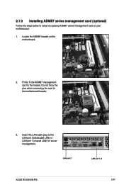
Do not force the pins when connecting the card to install an optional ASMB7 series management card on the motherboard. 2. 2.7.3 Installing ASMB7 series management card (optional) Follow the steps below to the motherboard header. 3. Locate the ASMB7 header on your motherboard. 1. Insert the LAN cable plug to the header. Firmly fit the ASMB7 management card to the LAN port 3 (dedicated LAN) or LAN port 1 (shared LAN) for server management. LAN port 3 ASUS RS100-E8-PI2 LAN port 1~2 2-27
Do not force the pins when connecting the card to install an optional ASMB7 series management card on the motherboard. 2. 2.7.3 Installing ASMB7 series management card (optional) Follow the steps below to the motherboard header. 3. Locate the ASMB7 header on your motherboard. 1. Insert the LAN cable plug to the header. Firmly fit the ASMB7 management card to the LAN port 3 (dedicated LAN) or LAN port 1 (shared LAN) for server management. LAN port 3 ASUS RS100-E8-PI2 LAN port 1~2 2-27

User Guide
Page 49
ASUS RS100-E8-PI2 3-3 Place three (3) nuts on the rack where you wish to install the server. 4. Select one unit of space (1U) on the front and three at ...
ASUS RS100-E8-PI2 3-3 Place three (3) nuts on the rack where you wish to install the server. 4. Select one unit of space (1U) on the front and three at ...
User Guide
Page 51
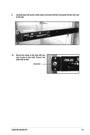
Secure the other side as well. Secure the server to the back until the front panel fits the front end of the rack. 10. 9. Rack screw ASUS RS100-E8-PI2 3-5 Carefully push the server all the way to the rack with one rack screw at one side.
Secure the other side as well. Secure the server to the back until the front panel fits the front end of the rack. 10. 9. Rack screw ASUS RS100-E8-PI2 3-5 Carefully push the server all the way to the rack with one rack screw at one side.

User Guide
Page 55
... 3. Power-on Button 9. Location LED (LOC_LED1) 4. VGA controller setting (3-pin VGA_SW1) 3. USB 3.0 ports 1 and 2 Page 4-10 4-10 4-10 4-10 4-10 4-10 4-10 4-10 4-10 4-10 ASUS RS100-E8-PI2 4-3 LAN controller setting (3-pin LAN_SW1, LAN_SW2,) 4. VGA connector (16-1 pin VGA_HDR1) Page 4-7 4-8 4-8 4-8 4-9 4-9 4-9 Rear panel connectors 1. COM1 port 4. Platform Environmental Control Interface Setting (3-pin PECI1) 6. Video...
... 3. Power-on Button 9. Location LED (LOC_LED1) 4. VGA controller setting (3-pin VGA_SW1) 3. USB 3.0 ports 1 and 2 Page 4-10 4-10 4-10 4-10 4-10 4-10 4-10 4-10 4-10 4-10 ASUS RS100-E8-PI2 4-3 LAN controller setting (3-pin LAN_SW1, LAN_SW2,) 4. VGA connector (16-1 pin VGA_HDR1) Page 4-7 4-8 4-8 4-8 4-9 4-9 4-9 Rear panel connectors 1. COM1 port 4. Platform Environmental Control Interface Setting (3-pin PECI1) 6. Video...
User Guide
Page 57
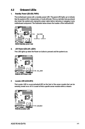
... removing or plugging in soft-off . It is used to indicate that the system is a reminder that can be remotely turned on or off mode. ASUS RS100-E8-PI2 4-5 This is ON, in sleep mode, or in any motherboard component.
... removing or plugging in soft-off . It is used to indicate that the system is a reminder that can be remotely turned on or off mode. ASUS RS100-E8-PI2 4-5 This is ON, in sleep mode, or in any motherboard component.


