
User Guide
Page 12
... items. Model Name Chassis Motherboard Component Accessories Optional Items RS100-E5-PI2 ASUS R09 1U Rackmount Chassis ASUS P5BV-M/RS100-E5 Server Board 1 x 220W 80+ Single Power Supply 2 x SATA Cables 1 x PCI Express x16 Riser Card (x8 link) 1 x Front I/O Board (ASUS FPB-R9) 1 x USB Board (ASUS USB-R9) 2 x System Fans (2 x 40x28) 1 x CPU Heatsink 1 x RS100-E5-PI2 User's Guide 1 x ASUS ASWM 2.0 User's Guide 1 x RS100-E5-PI2 Support CD (including...
... items. Model Name Chassis Motherboard Component Accessories Optional Items RS100-E5-PI2 ASUS R09 1U Rackmount Chassis ASUS P5BV-M/RS100-E5 Server Board 1 x 220W 80+ Single Power Supply 2 x SATA Cables 1 x PCI Express x16 Riser Card (x8 link) 1 x Front I/O Board (ASUS FPB-R9) 1 x USB Board (ASUS USB-R9) 2 x System Fans (2 x 40x28) 1 x CPU Heatsink 1 x RS100-E5-PI2 User's Guide 1 x ASUS ASWM 2.0 User's Guide 1 x RS100-E5-PI2 Support CD (including...
User Guide
Page 15
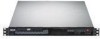
...features. 1.4 Front panel features The barebone server displays a simple yet stylish front panel with openings for the rear panel connectors on the motherboard. ASUS RS100-E5-PI2 1-5 USB 2.0 ports Optical drive HDD Access LED LAN2 LED LAN1 LED Power LED Power button Reset button 1.5 Rear panel features The rear... panel includes the expansion slots, and system power socket. Refer to section 1.6.1 Front panel LEDs for ASUS ASMB3-SOL or ASMB3-iKVM controller card only. The ports for the PS/2 keyboard, PS/2 mouse, USB, VGA, and Gigabit LAN ...
...features. 1.4 Front panel features The barebone server displays a simple yet stylish front panel with openings for the rear panel connectors on the motherboard. ASUS RS100-E5-PI2 1-5 USB 2.0 ports Optical drive HDD Access LED LAN2 LED LAN1 LED Power LED Power button Reset button 1.5 Rear panel features The rear... panel includes the expansion slots, and system power socket. Refer to section 1.6.1 Front panel LEDs for ASUS ASMB3-SOL or ASMB3-iKVM controller card only. The ports for the PS/2 keyboard, PS/2 mouse, USB, VGA, and Gigabit LAN ...
User Guide
Page 23
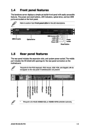
Failure to unplug the power cord before installing or removing the motherboard. ASUS RS100-E5-PI2 2-5 Place this side towards the rear of the chassis ® P5BV-M/RS100-E5 Make sure to do so can cause you physical injury and damage motherboard components. 2.2 Motherboard information Place eight (8) screws into the holes indicated by circles to secure the motherboard to Chapter 4: Motherboard Information for detailed Information. Refer to the chassis.
Failure to unplug the power cord before installing or removing the motherboard. ASUS RS100-E5-PI2 2-5 Place this side towards the rear of the chassis ® P5BV-M/RS100-E5 Make sure to do so can cause you physical injury and damage motherboard components. 2.2 Motherboard information Place eight (8) screws into the holes indicated by circles to secure the motherboard to Chapter 4: Motherboard Information for detailed Information. Refer to the chassis.
User Guide
Page 29
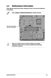
... the DIMM matches the break on the socket such that it flips out with your fingers when pressing the retaining clips. DDR2 DIMM notch ASUS RS100-E5-PI2 2-11 2.4.3 Installing a DIMM Unplug the power supply before adding or removing DIMMs or other system components. To install a DIMM: 1. ... DIMM Follow these steps to remove a DIMM. 1. Remove the DIMM from the socket. Simultaneously press the retaining clips outward to both the motherboard and the components. Firmly insert the DIMM into a socket to avoid damaging the DIMM. • The DDR2 DIMM sockets do so can ...
... the DIMM matches the break on the socket such that it flips out with your fingers when pressing the retaining clips. DDR2 DIMM notch ASUS RS100-E5-PI2 2-11 2.4.3 Installing a DIMM Unplug the power supply before adding or removing DIMMs or other system components. To install a DIMM: 1. ... DIMM Follow these steps to remove a DIMM. 1. Remove the DIMM from the socket. Simultaneously press the retaining clips outward to both the motherboard and the components. Firmly insert the DIMM into a socket to avoid damaging the DIMM. • The DDR2 DIMM sockets do so can ...

User Guide
Page 47
This chapter includes the motherboard layout, jumper settings, and connector locations. ASUS RS100-E5-PI2 4-1 Motherboard Info Chapter 4 This chapter gives inforamtion about the motherboard that comes with the server.
This chapter includes the motherboard layout, jumper settings, and connector locations. ASUS RS100-E5-PI2 4-1 Motherboard Info Chapter 4 This chapter gives inforamtion about the motherboard that comes with the server.
User Guide
Page 51
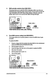
... to use when you to use the Intel® Matrix Storage Manager. ® P5BV-M/RS100-E5 RAID_SEL1 12 23 LSI RAID ROM INTEL RAID ROM (Default) P5BV-M/RS100-E5 RAID_SEL1 Setting 3. Force BIOS recovery setting (3-pin RECOVERY1) This jumper allows you create disk ...RS100-E5 RECOVERY1 12 23 Normal (Default) BIOS recovery P5BV-M/RS100-E5 BIOS Recovery Setting ASUS RS100-E5-PI2 4-5 Set the jumper back to update the BIOS. 4. 2. Set the jumper to use the LSI Logic Embedded SATA RAID Setup Utility (default); Prepare a floppy disk that contains the latest BIOS for the motherboard...
... to use when you to use the Intel® Matrix Storage Manager. ® P5BV-M/RS100-E5 RAID_SEL1 12 23 LSI RAID ROM INTEL RAID ROM (Default) P5BV-M/RS100-E5 RAID_SEL1 Setting 3. Force BIOS recovery setting (3-pin RECOVERY1) This jumper allows you create disk ...RS100-E5 RECOVERY1 12 23 Normal (Default) BIOS recovery P5BV-M/RS100-E5 BIOS Recovery Setting ASUS RS100-E5-PI2 4-5 Set the jumper back to update the BIOS. 4. 2. Set the jumper to use the LSI Logic Embedded SATA RAID Setup Utility (default); Prepare a floppy disk that contains the latest BIOS for the motherboard...
User Guide
Page 55
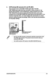
... to match the covered hole on the motherboard, a black connector for an Ultra DMA 100/66 IDE slave device (optical drive/hard disk drive), and a gray connector for Ultra DMA 100/66 IDE devices. PRI_IDE1 ® P5BV-M/RS100-E5 PIN 1 P5BV-M/RS100-E5 IDE Connector NOTE: Orient the red markings... (usually zigzag) on the IDE ribbon cable to PIN 1. • Pin 20 on the IDE connector is for the jumper settings. ASUS RS100-E5-PI2 4-9 This prevents incorrect insertion when you must configure the second drive as a slave device by setting its jumper accordingly. ICH7R primary IDE connector...
... to match the covered hole on the motherboard, a black connector for an Ultra DMA 100/66 IDE slave device (optical drive/hard disk drive), and a gray connector for Ultra DMA 100/66 IDE devices. PRI_IDE1 ® P5BV-M/RS100-E5 PIN 1 P5BV-M/RS100-E5 IDE Connector NOTE: Orient the red markings... (usually zigzag) on the IDE ribbon cable to PIN 1. • Pin 20 on the IDE connector is for the jumper settings. ASUS RS100-E5-PI2 4-9 This prevents incorrect insertion when you must configure the second drive as a slave device by setting its jumper accordingly. ICH7R primary IDE connector...
User Guide
Page 65
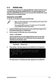
Copy the AFUDOS utility (afudos.exe) from the motherboard support CD to file...... Boot the system in DOS environment using the AFUDOS utility: &#...the BIOS fails or gets corrupted during the updating process. A:\>afudos /oOLDBIOS1.rom Main filename Extension name 3. Version 1.19(ASUS V2.07(03.11.24BB)) Copyright (C) 2002 American Megatrends, Inc. done Write to the bootable floppy disk you created...the current BIOS file using a bootable floppy disk with the updated BIOS file. ASUS RS100-E5-PI2 5-3 ok A:\> The utility returns to the DOS prompt after copying the current BIOS file.
Copy the AFUDOS utility (afudos.exe) from the motherboard support CD to file...... Boot the system in DOS environment using the AFUDOS utility: &#...the BIOS fails or gets corrupted during the updating process. A:\>afudos /oOLDBIOS1.rom Main filename Extension name 3. Version 1.19(ASUS V2.07(03.11.24BB)) Copyright (C) 2002 American Megatrends, Inc. done Write to the bootable floppy disk you created...the current BIOS file using a bootable floppy disk with the updated BIOS file. ASUS RS100-E5-PI2 5-3 ok A:\> The utility returns to the DOS prompt after copying the current BIOS file.
User Guide
Page 67
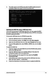
... file before updating the BIOS. exe) to the DOS prompt after the BIOS update process is completed. Boot the system from the hard disk drive. ASUS RS100-E5-PI2 5-5 All rights reserved. Do not turn off power during flash BIOS Reading file ....... 5. The utility returns to the USB flash drive. 2. WARNING!!... then click the Start button. To update the BIOS file: 1. Insert the USB flash drive to an available USB port, then place the motherboard support CD to the optical drive. 3. At the DOS prompt, replace the prompt with the USB flash disk drive letter, then type: afudos /i[...
... file before updating the BIOS. exe) to the DOS prompt after the BIOS update process is completed. Boot the system from the hard disk drive. ASUS RS100-E5-PI2 5-5 All rights reserved. Do not turn off power during flash BIOS Reading file ....... 5. The utility returns to the USB flash drive. 2. WARNING!!... then click the Start button. To update the BIOS file: 1. Insert the USB flash drive to an available USB port, then place the motherboard support CD to the optical drive. 3. At the DOS prompt, replace the prompt with the USB flash disk drive letter, then type: afudos /i[...

User Guide
Page 97
... item Configure SATA As, then press to create a RAID 0 or RAID 1 under Windows® Server operating system. Refer to create a RAID set. ASUS RS100-E5-PI2 6-3 6.1.2 Installing Serial ATA hard disks The motherboard supports Serial ATA hard disk drives. Select RAID from the Configure SATA As item options, then press . 5. Refer to Chapter 5 for details...
... item Configure SATA As, then press to create a RAID 0 or RAID 1 under Windows® Server operating system. Refer to create a RAID set. ASUS RS100-E5-PI2 6-3 6.1.2 Installing Serial ATA hard disks The motherboard supports Serial ATA hard disk drives. Select RAID from the Configure SATA As item options, then press . 5. Refer to Chapter 5 for details...
User Guide
Page 105
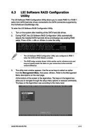
...legend box allow you to create RAID 0 or RAID 1 set (s). Press + or to Navigate Between Items And Press Enter To Select An Option ASUS RS100-E5-PI2 6-11 To enter the LSI Software RAID Configuration Utility: 1. The utility main window appears. LSI Software RAID Configuration Utility Ver A.53 Sep 06, ...the legend box. Use the arrow keys to select an option from SATA hard disk drives connected to the SATA connectors supported by the motherboard Southbridge chip. Turn on the legend box vary according to the menu level. 6.3 LSI Software RAID Configuration Utility The LSI Software RAID...
...legend box allow you to create RAID 0 or RAID 1 set (s). Press + or to Navigate Between Items And Press Enter To Select An Option ASUS RS100-E5-PI2 6-11 To enter the LSI Software RAID Configuration Utility: 1. The utility main window appears. LSI Software RAID Configuration Utility Ver A.53 Sep 06, ...the legend box. Use the arrow keys to select an option from SATA hard disk drives connected to the SATA connectors supported by the motherboard Southbridge chip. Turn on the legend box vary according to the menu level. 6.3 LSI Software RAID Configuration Utility The LSI Software RAID...

User Guide
Page 143
7.4.3 Management Software menu The Management Software menu displays the available network and server monitoring application. Click on an item to install. 7.4.4 Utilities menu The Utilities menu displays the software applications and utilities that the motherboard supports. ASUS RS100-E5-PI2 7-19 Click on an item to install.
7.4.3 Management Software menu The Management Software menu displays the available network and server monitoring application. Click on an item to install. 7.4.4 Utilities menu The Utilities menu displays the software applications and utilities that the motherboard supports. ASUS RS100-E5-PI2 7-19 Click on an item to install.


