User Guide
Page 9
... basic knowledge of configuring a server. ix Chapter 3: Installation options This chapter describes how to when configuring the motherboard. This chapter includes the motherboard layout, jumper settings, and connector locations. 5. Detailed descriptions of the server, including sections on front panel and rear panel specifications. 2. About this guide Audience This user guide is intended for different system components. 8. Chapter 2: Hardware setup This chapter lists the hardware setup procedures that you have to change system settings through the BIOS Setup menus and...
... basic knowledge of configuring a server. ix Chapter 3: Installation options This chapter describes how to when configuring the motherboard. This chapter includes the motherboard layout, jumper settings, and connector locations. 5. Detailed descriptions of the server, including sections on front panel and rear panel specifications. 2. About this guide Audience This user guide is intended for different system components. 8. Chapter 2: Hardware setup This chapter lists the hardware setup procedures that you have to change system settings through the BIOS Setup menus and...
User Guide
Page 10
... value enclosed in brackets. ASUS Server Web-based Management (ASWM) user guide This manual tells how to complete a task. Example: ++ Command Means that you must press the enclosed key. ASUS websites The ASUS websites worldwide provide updated information for product and software updates. 1. DANGER/WARNING: Information to prevent injury to yourself when trying to set up and use the proprietary ASUS server management utility. 2. NOTE: Tips and additional...
... value enclosed in brackets. ASUS Server Web-based Management (ASWM) user guide This manual tells how to complete a task. Example: ++ Command Means that you must press the enclosed key. ASUS websites The ASUS websites worldwide provide updated information for product and software updates. 1. DANGER/WARNING: Information to prevent injury to yourself when trying to set up and use the proprietary ASUS server management utility. 2. NOTE: Tips and additional...
User Guide
Page 13
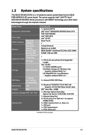
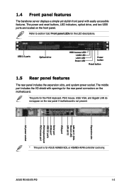
...Slim-type Optical Device Bay Options: No Device / DVD-ROM / DVD-RW 1 x External Serial Port 3 x RJ-45 ports (2 for GbE and 1 for Linux/Windows) - Supports software RAID 0 & 1 LSI MegaRAID (for optional ASMB3-iKVM) 4 x USB 2.0 ports (Front x 2, Rear x 2) 1 x VGA port 1 x PS/2 keyboard port 1 x PS/2 mouse port (continued on the next page) ASUS RS100-E5-PI2 1-3 Model Name Processor / System Bus Core Logic ASUS Features Smart Fan ASWM2.0 Total Slots Memory Capacity Memory Type Memory Size Total PCI/PCI-X/ Expansion Slots PCI-E Slots Slot Type Storage SATA Controller HDD Bays...
...Slim-type Optical Device Bay Options: No Device / DVD-ROM / DVD-RW 1 x External Serial Port 3 x RJ-45 ports (2 for GbE and 1 for Linux/Windows) - Supports software RAID 0 & 1 LSI MegaRAID (for optional ASMB3-iKVM) 4 x USB 2.0 ports (Front x 2, Rear x 2) 1 x VGA port 1 x PS/2 keyboard port 1 x PS/2 mouse port (continued on the next page) ASUS RS100-E5-PI2 1-3 Model Name Processor / System Bus Core Logic ASUS Features Smart Fan ASWM2.0 Total Slots Memory Capacity Memory Type Memory Size Total PCI/PCI-X/ Expansion Slots PCI-E Slots Slot Type Storage SATA Controller HDD Bays...
User Guide
Page 15
...USB, VGA, and Gigabit LAN do not appear on the front panel. ASUS RS100-E5-PI2 1-5 The middle part includes the I/O shield with easily accessible features. USB 2.0 ports Optical drive HDD Access LED LAN2 LED LAN1 LED Power LED Power button Reset button 1.5 Rear panel features The rear panel includes the expansion slots, and system power socket. The power and reset buttons, LED indicators, optical drive, and two USB ports are located on the rear panel if motherboard is for the LED descriptions. Refer to section 1.6.1 Front panel LEDs for ASUS ASMB3-SOL or ASMB3-iKVM controller card...
...USB, VGA, and Gigabit LAN do not appear on the front panel. ASUS RS100-E5-PI2 1-5 The middle part includes the I/O shield with easily accessible features. USB 2.0 ports Optical drive HDD Access LED LAN2 LED LAN1 LED Power LED Power button Reset button 1.5 Rear panel features The rear panel includes the expansion slots, and system power socket. The power and reset buttons, LED indicators, optical drive, and two USB ports are located on the rear panel if motherboard is for the LED descriptions. Refer to section 1.6.1 Front panel LEDs for ASUS ASMB3-SOL or ASMB3-iKVM controller card...
User Guide
Page 33
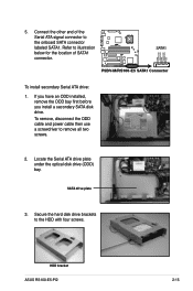
... install a secondary SATA disk drive. Secure the hard disk drive brackets to remove all two screws. 2. HDD bracket ASUS RS100-E5-PI2 2-15 Refer to illustration below for the location of the Serial ATA signal connector to the onboard SATA connector labeled SATA1. To remove, disconnect the ODD cable and power cable then use a screwdriver to the HDD with four screws. Locate the Serial ATA drive plate under the optical disk drive (ODD) bay. 5. Connect the other end of SATA1 connector...
... install a secondary SATA disk drive. Secure the hard disk drive brackets to remove all two screws. 2. HDD bracket ASUS RS100-E5-PI2 2-15 Refer to illustration below for the location of the Serial ATA signal connector to the onboard SATA connector labeled SATA1. To remove, disconnect the ODD cable and power cable then use a screwdriver to the HDD with four screws. Locate the Serial ATA drive plate under the optical disk drive (ODD) bay. 5. Connect the other end of SATA1 connector...
User Guide
Page 35
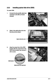
Align the screw hole of the ODD bracket with the screw hole on the SATA drive bracket, then secure it with a screw. ODD bracket Optical disk drive (optional) ASUS RS100-E5-PI2 2-17 Slide in the optical disk drive into the drive slot as shown. Optical disk drive slot 3. Connect the 80-pin IDE cable blue connector to the IDE connector onboard. 2. 2.5.3 Installing optical disk drive (ODD) To install ODD: 1.
Align the screw hole of the ODD bracket with the screw hole on the SATA drive bracket, then secure it with a screw. ODD bracket Optical disk drive (optional) ASUS RS100-E5-PI2 2-17 Slide in the optical disk drive into the drive slot as shown. Optical disk drive slot 3. Connect the 80-pin IDE cable blue connector to the IDE connector onboard. 2. 2.5.3 Installing optical disk drive (ODD) To install ODD: 1.
User Guide
Page 36
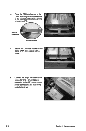
Secure the ODD side bracket to the IDE connector and power connector at the rear of the optical disk drive. 2-18 Chapter 2: Hardware setup Connect the 80-pin IDE cable black connector and 4-pin ATX power connector to the Serial SATA drive bracket with the holes on the side of the bracket with a screw. 6. Bracket connectors ODD side bracket 5. 4. Place the ODD side bracket to the ODD, matching the two connectors of the ODD.
Secure the ODD side bracket to the IDE connector and power connector at the rear of the optical disk drive. 2-18 Chapter 2: Hardware setup Connect the 80-pin IDE cable black connector and 4-pin ATX power connector to the Serial SATA drive bracket with the holes on the side of the bracket with a screw. 6. Bracket connectors ODD side bracket 5. 4. Place the ODD side bracket to the ODD, matching the two connectors of the ODD.
User Guide
Page 49
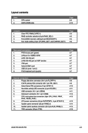
...System panel connector (20-pin PANEL1) 10. Serial (COM1) port 7. PS/2 keyboard port (purple) Internal connectors 1. Hard disk activity LED connector (4-pin HDLED1) 5. CPU and system fan connectors (4pin CPU_FAN1, FRNT_ FAN1, REAR_FAN1) 8. Layout contents Slots 1. 2. LAN port for ASMB3 iKVM 3. CPU socket DDR2 DIMM slots Page 2-6 2-10 Jumpers 1. Fan mode setting (3-pin CPUFAN_SET1 and CHAFAN_SET1) Page 4-4 4-5 4-5 4-6 Rear panel connectors 1. ICH7R primary IDE connector (40-1 pin PRI_IDE1) 3. PS/2 mouse port (green) 2. Clear RTC RAM (CLRTC1) 2. ATX power...
...System panel connector (20-pin PANEL1) 10. Serial (COM1) port 7. PS/2 keyboard port (purple) Internal connectors 1. Hard disk activity LED connector (4-pin HDLED1) 5. CPU and system fan connectors (4pin CPU_FAN1, FRNT_ FAN1, REAR_FAN1) 8. Layout contents Slots 1. 2. LAN port for ASMB3 iKVM 3. CPU socket DDR2 DIMM slots Page 2-6 2-10 Jumpers 1. Fan mode setting (3-pin CPUFAN_SET1 and CHAFAN_SET1) Page 4-4 4-5 4-5 4-6 Rear panel connectors 1. ICH7R primary IDE connector (40-1 pin PRI_IDE1) 3. PS/2 mouse port (green) 2. Clear RTC RAM (CLRTC1) 2. ATX power...

User Guide
Page 50
... CMOS memory of date, time, and system setup parameters by erasing the CMOS RTC RAM data. You must turn ON the computer. 4. The onboard button cell battery powers the RAM data in CMOS. Move the jumper cap from pins 1-2 (default) to overclocking, use the C.P.R. (CPU Parameter Recall) feature. After the CMOS clearance, reinstall the battery. ® P5BV-M/RS100-E5 CLRTC1 12 23 Normal (Default) P5BV-M/RS100-E5 Clear RTC RAM Clear CMOS • You do not help, remove...
... CMOS memory of date, time, and system setup parameters by erasing the CMOS RTC RAM data. You must turn ON the computer. 4. The onboard button cell battery powers the RAM data in CMOS. Move the jumper cap from pins 1-2 (default) to overclocking, use the C.P.R. (CPU Parameter Recall) feature. After the CMOS clearance, reinstall the battery. ® P5BV-M/RS100-E5 CLRTC1 12 23 Normal (Default) P5BV-M/RS100-E5 Clear RTC RAM Clear CMOS • You do not help, remove...
User Guide
Page 51
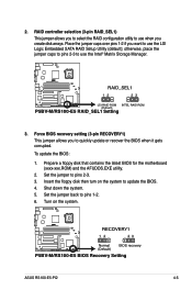
...-M/RS100-E5 RECOVERY1 12 23 Normal (Default) BIOS recovery P5BV-M/RS100-E5 BIOS Recovery Setting ASUS RS100-E5-PI2 4-5 2. Place the jumper caps over pins 1-2 if you want to use the LSI Logic Embedded SATA RAID Setup Utility (default); otherwise, place the jumper caps to pins 2-3 to use the Intel® Matrix Storage Manager. ® P5BV-M/RS100-E5 RAID_SEL1 12 23 LSI RAID ROM INTEL RAID ROM (Default) P5BV-M/RS100-E5 RAID_SEL1 Setting 3. Turn on the system to pins 1-2. 6. Prepare a floppy disk that contains the latest BIOS for the motherboard...
...-M/RS100-E5 RECOVERY1 12 23 Normal (Default) BIOS recovery P5BV-M/RS100-E5 BIOS Recovery Setting ASUS RS100-E5-PI2 4-5 2. Place the jumper caps over pins 1-2 if you want to use the LSI Logic Embedded SATA RAID Setup Utility (default); otherwise, place the jumper caps to pins 2-3 to use the Intel® Matrix Storage Manager. ® P5BV-M/RS100-E5 RAID_SEL1 12 23 LSI RAID ROM INTEL RAID ROM (Default) P5BV-M/RS100-E5 RAID_SEL1 Setting 3. Turn on the system to pins 1-2. 6. Prepare a floppy disk that contains the latest BIOS for the motherboard...
User Guide
Page 53
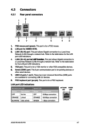
... mouse. 2. 4.3 Connectors 4.3.1 Rear panel connectors 1 2 8 7 6 5 4 3 1. LAN1 (RJ-45) port. Refer to the table below for a VGA monitor or other serial devices. 7. This 9-pin communication port is for the LAN port LED indications. 5. USB 2.0 ports 1 and 2. LAN port LED indications Activity/Link LED Status Description OFF No link ORANGE Linked BLINKING Data activity Speed LED Status Description OFF 10 Mbps connection ORANGE 100 Mbps connection GREEN 1 Gbps connection ACT/LINK SPEED LED LED LAN port ASUS RS100-E5-PI2 4-7 PS/2 mouse port (green). This port...
... mouse. 2. 4.3 Connectors 4.3.1 Rear panel connectors 1 2 8 7 6 5 4 3 1. LAN1 (RJ-45) port. Refer to the table below for a VGA monitor or other serial devices. 7. This 9-pin communication port is for the LAN port LED indications. 5. USB 2.0 ports 1 and 2. LAN port LED indications Activity/Link LED Status Description OFF No link ORANGE Linked BLINKING Data activity Speed LED Status Description OFF 10 Mbps connection ORANGE 100 Mbps connection GREEN 1 Gbps connection ACT/LINK SPEED LED LED LAN port ASUS RS100-E5-PI2 4-7 PS/2 mouse port (green). This port...
User Guide
Page 55
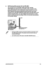
... configure the second drive as a slave device by setting its jumper accordingly. 2. ASUS RS100-E5-PI2 4-9 Refer to match the covered hole on the motherboard, a black connector for an Ultra DMA 100/66 IDE slave device (optical drive/hard disk drive), and a gray connector for an Ultra DMA 100/66 signal cable. ICH7R primary IDE connector (40-1 pin PRI_IDE1) This connector is removed to the hard disk documentation for Ultra DMA 100/66 IDE devices. If you install...
... configure the second drive as a slave device by setting its jumper accordingly. 2. ASUS RS100-E5-PI2 4-9 Refer to match the covered hole on the motherboard, a black connector for an Ultra DMA 100/66 IDE slave device (optical drive/hard disk drive), and a gray connector for an Ultra DMA 100/66 signal cable. ICH7R primary IDE connector (40-1 pin PRI_IDE1) This connector is removed to the hard disk documentation for Ultra DMA 100/66 IDE devices. If you install...
User Guide
Page 70
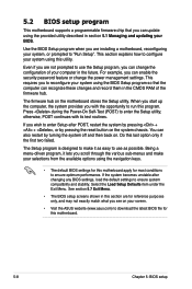
... change the power management settings. 5.2 BIOS setup program This motherboard supports a programmable firmware chip that the computer can recognize these changes and record them in the CMOS RAM of your selections from the available options using the BIOS Setup program so that you scroll through the various sub-menus and make it lets you can update using the provided utility described in section 5.1 Managing and updating your screen. • Visit the ASUS website (www.asus...
... change the power management settings. 5.2 BIOS setup program This motherboard supports a programmable firmware chip that the computer can recognize these changes and record them in the CMOS RAM of your selections from the available options using the BIOS Setup program so that you scroll through the various sub-menus and make it lets you can update using the provided utility described in section 5.1 Managing and updating your screen. • Visit the ASUS website (www.asus...
User Guide
Page 74
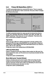
... are specifically configuring a CD-ROM drive. When set to [Disabled], the data transfer from and to display the IDE device information. Select a device item, then press to the device occurs multiple sectors at a time. Select Screen Select Item +- Select [ARMD] (ATAPI Removable Media Device) if your device is installed in the system. Type [Auto] Selects the type of device connected to the device occurs one sector at a time if the device supports multi...
... are specifically configuring a CD-ROM drive. When set to [Disabled], the data transfer from and to display the IDE device information. Select a device item, then press to the device occurs multiple sectors at a time. Select Screen Select Item +- Select [ARMD] (ATAPI Removable Media Device) if your device is installed in the system. Type [Auto] Selects the type of device connected to the device occurs one sector at a time if the device supports multi...
User Guide
Page 79
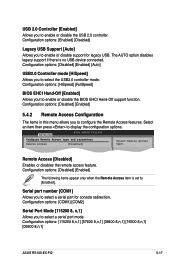
... no USB device connected. Configuration options: [Enabled] [Disabled] Legacy USB Support [Auto] Allows you to select a serial port mode. Configuration options: [COM1] [COM2] Serial Port Mode [115200 8, n,1] Allows you to enable or disable support for console redirection. The AUTO option disables legacy support if there is set to [Enabled]. Select an item then press to enable or disable the USB 2.0 controller. USB 2.0 Controller [Enabled] Allows you to display the configuration options. Advanced BIOS SETUP UTILITY Configure Remote Access type and parameters Remote Access [Disabled...
... no USB device connected. Configuration options: [Enabled] [Disabled] Legacy USB Support [Auto] Allows you to select a serial port mode. Configuration options: [COM1] [COM2] Serial Port Mode [115200 8, n,1] Allows you to enable or disable support for console redirection. The AUTO option disables legacy support if there is set to [Enabled]. Select an item then press to enable or disable the USB 2.0 controller. USB 2.0 Controller [Enabled] Allows you to display the configuration options. Advanced BIOS SETUP UTILITY Configure Remote Access type and parameters Remote Access [Disabled...

User Guide
Page 92
BIOS SETUP UTILITY Boot Security Settings Supervisor Password User Password : Not Installed : Not Installed Change Supervisor Password Change User Password to disable password. again to change password. The Supervisor Password item on how to erase the RTC RAM. 5.6.3 Security The Security menu items allow you to change other items appear to allow you to display the configuration options. To change the supervisor password. See section 2.6 Jumper for information on top of at least six letters and/or numbers, then press . 3. After...
BIOS SETUP UTILITY Boot Security Settings Supervisor Password User Password : Not Installed : Not Installed Change Supervisor Password Change User Password to disable password. again to change password. The Supervisor Password item on how to erase the RTC RAM. 5.6.3 Security The Security menu items allow you to change other items appear to allow you to display the configuration options. To change the supervisor password. See section 2.6 Jumper for information on top of at least six letters and/or numbers, then press . 3. After...

User Guide
Page 97
... jumper settings. ASUS RS100-E5-PI2 6-3 Go to display the configuration options. 4. Refer to use the RAID configuration utilities. 6.1.2 Installing Serial ATA hard disks The motherboard supports Serial ATA hard disk drives. Select RAID from the Configure SATA As item options, then press . 5. Use the Intel® Matrix Storage Manager to create a RAID 0 or RAID 1 under Windows® Server operating system. Enter the BIOS Setup during POST. 2. Save your changes, then exit the BIOS Setup. Use the LSI Software RAID Configuration Utility to create a RAID 0 or RAID 1 set...
... jumper settings. ASUS RS100-E5-PI2 6-3 Go to display the configuration options. 4. Refer to use the RAID configuration utilities. 6.1.2 Installing Serial ATA hard disks The motherboard supports Serial ATA hard disk drives. Select RAID from the Configure SATA As item options, then press . 5. Use the Intel® Matrix Storage Manager to create a RAID 0 or RAID 1 under Windows® Server operating system. Enter the BIOS Setup during POST. 2. Save your changes, then exit the BIOS Setup. Use the LSI Software RAID Configuration Utility to create a RAID 0 or RAID 1 set...
User Guide
Page 105
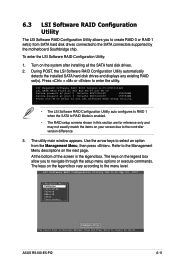
... Enter to run LSI Software RAID Setup Utility. - • The LSI Software RAID Configuration Utitlity auto configures to RAID 1 when the SATA to RAID Mode is the legend box. Turn on the next page. During POST, the LSI Software RAID Configuration Utility automatically detects the installed SATA hard disk drives and displays any existing RAID set (s) from SATA hard disk drives connected to select an option from the Management Menu, then press . The keys on the legend box allow you to create RAID 0 or RAID 1 set (s). The utility main window appears...
... Enter to run LSI Software RAID Setup Utility. - • The LSI Software RAID Configuration Utitlity auto configures to RAID 1 when the SATA to RAID Mode is the legend box. Turn on the next page. During POST, the LSI Software RAID Configuration Utility automatically detects the installed SATA hard disk drives and displays any existing RAID set (s) from SATA hard disk drives connected to select an option from the Management Menu, then press . The keys on the legend box allow you to create RAID 0 or RAID 1 set (s). The utility main window appears...
User Guide
Page 126
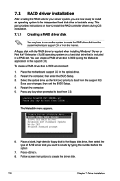
... driver disk. 7-2 Chapter 7: Driver installation Press any key to boot from CDROM... Follow screen instructions to create by typing the number before the option 7. You can create a RAID driver disk in DOS (using the Makedisk application in the optical drive. 2. The Makedisk menu appears. To create a RAID driver disk in a RAID set. A floppy disk with the RAID driver is required when installing Windows® Server or Red Hat® Enterprise / SuSE operating system on how to install the RAID controller drivers during OS installation. 7.1.1 Creating a RAID driver disk...
... driver disk. 7-2 Chapter 7: Driver installation Press any key to boot from CDROM... Follow screen instructions to create by typing the number before the option 7. You can create a RAID driver disk in DOS (using the Makedisk application in the optical drive. 2. The Makedisk menu appears. To create a RAID driver disk in a RAID set. A floppy disk with the RAID driver is required when installing Windows® Server or Red Hat® Enterprise / SuSE operating system on how to install the RAID controller drivers during OS installation. 7.1.1 Creating a RAID driver disk...
User Guide
Page 128
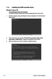
... During Windows® Server OS installation To install the RAID controller driver when installing Windows® Server OS: 1. Windows Setup Setup could not determine the type of the screen. 3. Currently, Setup will load support for the following mass storage devices(s): * To specify additional SCSI adapters, CD-ROM drives, or special disk controllers for use with Windows, including those for use with Windows, press ENTER. Press when the message "Press F6 if you need to specify an additional device. The Windows® Setup starts...
... During Windows® Server OS installation To install the RAID controller driver when installing Windows® Server OS: 1. Windows Setup Setup could not determine the type of the screen. 3. Currently, Setup will load support for the following mass storage devices(s): * To specify additional SCSI adapters, CD-ROM drives, or special disk controllers for use with Windows, including those for use with Windows, press ENTER. Press when the message "Press F6 if you need to specify an additional device. The Windows® Setup starts...


