
User Guide
Page 12
... Motherboard Component Accessories Optional Items RS100-E5-PI2 ASUS R09 1U Rackmount Chassis ASUS P5BV-M/RS100-E5 Server Board 1 x 220W 80+ Single Power Supply 2 x SATA Cables 1 x PCI Express x16 Riser Card (x8 link) 1 x Front I/O Board (ASUS FPB-R9) 1 x USB Board (ASUS USB-R9) 2 x System Fans (2 x 40x28) 1 x CPU Heatsink 1 x RS100-E5-PI2 User's Guide 1 x ASUS ASWM 2.0 User's Guide 1 x RS100-E5-PI2 Support CD (including ASWM...
... Motherboard Component Accessories Optional Items RS100-E5-PI2 ASUS R09 1U Rackmount Chassis ASUS P5BV-M/RS100-E5 Server Board 1 x 220W 80+ Single Power Supply 2 x SATA Cables 1 x PCI Express x16 Riser Card (x8 link) 1 x Front I/O Board (ASUS FPB-R9) 1 x USB Board (ASUS USB-R9) 2 x System Fans (2 x 40x28) 1 x CPU Heatsink 1 x RS100-E5-PI2 User's Guide 1 x ASUS ASWM 2.0 User's Guide 1 x RS100-E5-PI2 Support CD (including ASWM...
User Guide
Page 13
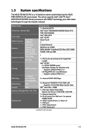
... ASMB3-iKVM) 4 x USB 2.0 ports (Front x 2, Rear x 2) 1 x VGA port 1 x PS/2 keyboard port 1 x PS/2 mouse port (continued on the next page) ASUS RS100-E5-PI2 1-3 1.3 System specifications The ASUS RS100-E5-PI2 is a 1U barebone server system featuring the ASUS P5BV-M/RS100-E5 server board. The server supports Intel® LGA775 Xeon® 3300/3200/3100/3000 Series processors with EM64T technology...
... ASMB3-iKVM) 4 x USB 2.0 ports (Front x 2, Rear x 2) 1 x VGA port 1 x PS/2 keyboard port 1 x PS/2 mouse port (continued on the next page) ASUS RS100-E5-PI2 1-3 1.3 System specifications The ASUS RS100-E5-PI2 is a 1U barebone server system featuring the ASUS P5BV-M/RS100-E5 server board. The server supports Intel® LGA775 Xeon® 3300/3200/3100/3000 Series processors with EM64T technology...
User Guide
Page 16
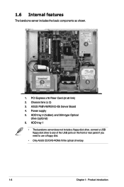
1.6 Internal features The barebone server includes the basic components as shown. 1 3 4 2 5 6 1. Chassis fans (x 2) 3. HDD tray 2 (hidden) and Slim-type Optical drive (optional) 6. HDD tray 1 • The barebone server does not include a floppy disk drive. connect a USB floppy disk drive to any of the USB ports on the front or rear panel if you need to use a floppy disk. • Only ASUS CD/DVD-ROMs fit the optical drive bay. 1-6 Chapter 1: Product introduction PCI Express x16 Riser Card (at x8 link) 2. ASUS P5BV-M/RS100-E5 Server Board 4. Power supply 5.
1.6 Internal features The barebone server includes the basic components as shown. 1 3 4 2 5 6 1. Chassis fans (x 2) 3. HDD tray 2 (hidden) and Slim-type Optical drive (optional) 6. HDD tray 1 • The barebone server does not include a floppy disk drive. connect a USB floppy disk drive to any of the USB ports on the front or rear panel if you need to use a floppy disk. • Only ASUS CD/DVD-ROMs fit the optical drive bay. 1-6 Chapter 1: Product introduction PCI Express x16 Riser Card (at x8 link) 2. ASUS P5BV-M/RS100-E5 Server Board 4. Power supply 5.
User Guide
Page 23
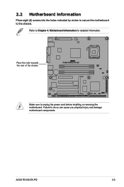
Place this side towards the rear of the chassis ® P5BV-M/RS100-E5 Make sure to Chapter 4: Motherboard Information for detailed Information. ASUS RS100-E5-PI2 2-5 Refer to unplug the power cord before installing or removing the motherboard. Failure to the chassis. 2.2 Motherboard information Place eight (8) screws into the holes indicated by circles to secure the motherboard to do so can cause you physical injury and damage motherboard components.
Place this side towards the rear of the chassis ® P5BV-M/RS100-E5 Make sure to Chapter 4: Motherboard Information for detailed Information. ASUS RS100-E5-PI2 2-5 Refer to unplug the power cord before installing or removing the motherboard. Failure to the chassis. 2.2 Motherboard information Place eight (8) screws into the holes indicated by circles to secure the motherboard to do so can cause you physical injury and damage motherboard components.

User Guide
Page 24
ASUS will process Return Merchandise Authorization (RMA) requests only if the motherboard comes with a surface mount LGA775 socket designed for the Intel® Xeon® 3300/.../socket contacts/motherboard components. ASUS shoulders the repair cost only if the damage is on the socket and the socket contacts are not bent. Locate the CPU socket on your left. 2-6 Chapter 2: Hardware setup Contact your retailer immediately if the PnP cap is on the motherboard. ® P5BV-M/RS100-E5 P5BV-M/RS100-E5 CPU Socket 775 Before...
ASUS will process Return Merchandise Authorization (RMA) requests only if the motherboard comes with a surface mount LGA775 socket designed for the Intel® Xeon® 3300/.../socket contacts/motherboard components. ASUS shoulders the repair cost only if the damage is on the socket and the socket contacts are not bent. Locate the CPU socket on your left. 2-6 Chapter 2: Hardware setup Contact your retailer immediately if the PnP cap is on the motherboard. ® P5BV-M/RS100-E5 P5BV-M/RS100-E5 CPU Socket 775 Before...
User Guide
Page 28
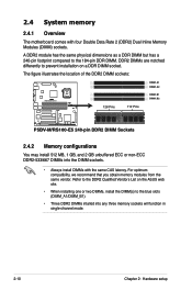
DDR2 DIMMs are notched differently to prevent installation on the ASUS web site. • When installing one or two DIMMs, install the DIMM(s) to the blue slots (DIMM_A1/DIMM_B1). • Three DDR2 DIMMs intalled into the ... 184-pin DDR DIMM. The figure illustrates the location of the DDR2 DIMM sockets: DIMM_A1 DIMM_A2 ® P5BV-M/RS100-E5 128 Pins 112 Pins DIMM_B1 DIMM_B2 P5BV-M/RS100-E5 240-pin DDR2 DIMM Sockets 2.4.2 Memory configurations You may install 512 MB, 1 GB, and 2 GB unbuffered ECC or non‑ECC DDR2-533/667 DIMMs into any three...
DDR2 DIMMs are notched differently to prevent installation on the ASUS web site. • When installing one or two DIMMs, install the DIMM(s) to the blue slots (DIMM_A1/DIMM_B1). • Three DDR2 DIMMs intalled into the ... 184-pin DDR DIMM. The figure illustrates the location of the DDR2 DIMM sockets: DIMM_A1 DIMM_A2 ® P5BV-M/RS100-E5 128 Pins 112 Pins DIMM_B1 DIMM_B2 P5BV-M/RS100-E5 240-pin DDR2 DIMM Sockets 2.4.2 Memory configurations You may install 512 MB, 1 GB, and 2 GB unbuffered ECC or non‑ECC DDR2-533/667 DIMMs into any three...
User Guide
Page 31
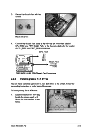
... screws. ASUS RS100-E5-PI2 2-13 Refer to install each of CPU_FAN1 and FRNT_FAN1 connectors. Follow the succeeding instructions to the illustration below for the location of the drives. Locate the Serial ATA drive bay beside the power supply unit. CPU_FAN1 GND FANPWR2 FAN PWM ® P5BV-M/RS100-E5 FRNT_FAN1 FAN PWM FANPWR2 GND P5BV-M/RS100-E5 CPU/Chassis...
... screws. ASUS RS100-E5-PI2 2-13 Refer to install each of CPU_FAN1 and FRNT_FAN1 connectors. Follow the succeeding instructions to the illustration below for the location of the drives. Locate the Serial ATA drive bay beside the power supply unit. CPU_FAN1 GND FANPWR2 FAN PWM ® P5BV-M/RS100-E5 FRNT_FAN1 FAN PWM FANPWR2 GND P5BV-M/RS100-E5 CPU/Chassis...
User Guide
Page 33
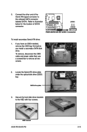
HDD bracket ASUS RS100-E5-PI2 2-15 Connect the other end of SATA1 connector. ® P5BV-M/RS100-E5 SATA1 GND RSATA_RXN1 RSATA_RXP1 GND RSATA_TXN1 RSATA_TXP1 GND P5BV-M/RS100-E5 SATA1 Connector To install secondary Serial ATA drive: 1. Refer to illustration below for the location of the Serial ATA signal connector to the onboard SATA ...
HDD bracket ASUS RS100-E5-PI2 2-15 Connect the other end of SATA1 connector. ® P5BV-M/RS100-E5 SATA1 GND RSATA_RXN1 RSATA_RXP1 GND RSATA_TXN1 RSATA_TXP1 GND P5BV-M/RS100-E5 SATA1 Connector To install secondary Serial ATA drive: 1. Refer to illustration below for the location of the Serial ATA signal connector to the onboard SATA ...
User Guide
Page 34
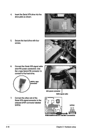
4. SATA L-type connector 7. ATX power connector SATA signal cable ® P5BV-M/RS100-E5 SATA3 GND RSATA_RXN1 RSATA_RXP1 GND RSATA_TXN1 RSATA_TXP1 GND P5BV-M/RS100-E5 SATA3 Connector 2-16 Chapter 2: Hardware setup Use the L-type Serial ATA connector to connect to the onboard SATA connector labeled SATA3. Connect the Serial ATA signal cable and ATX power connectors. Connect the other end of the Serial ATA signal connector to the hard drive. Secure the hard drive with four screws. 6. Insert the Serial ATA drive into the drive plate as shown. 5.
4. SATA L-type connector 7. ATX power connector SATA signal cable ® P5BV-M/RS100-E5 SATA3 GND RSATA_RXN1 RSATA_RXP1 GND RSATA_TXN1 RSATA_TXP1 GND P5BV-M/RS100-E5 SATA3 Connector 2-16 Chapter 2: Hardware setup Use the L-type Serial ATA connector to connect to the onboard SATA connector labeled SATA3. Connect the Serial ATA signal cable and ATX power connectors. Connect the other end of the Serial ATA signal connector to the hard drive. Secure the hard drive with four screws. 6. Insert the Serial ATA drive into the drive plate as shown. 5.
User Guide
Page 48
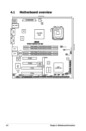
... (9.6in) 4.1 Motherboard overview PS/2KBMS T: Mouse B: Keyboard LAN_USB12 EATXPWR1 24.5cm (9.6in) ATX12V1 ISL 6312 COM1 VGA1 BCM 5721 BCM 5721 Intel 3200 MCH ® P5BV-M/RS100-E5 DDR2 DIMM_A1 (64 bit,240-pin module) LAN1 DDR2 DIMM_A2 (64 bit,240-pin module) LAN2 CR2032 3V Lithium Cell CMOS Power DDR2 DIMM_B1 (64...
... (9.6in) 4.1 Motherboard overview PS/2KBMS T: Mouse B: Keyboard LAN_USB12 EATXPWR1 24.5cm (9.6in) ATX12V1 ISL 6312 COM1 VGA1 BCM 5721 BCM 5721 Intel 3200 MCH ® P5BV-M/RS100-E5 DDR2 DIMM_A1 (64 bit,240-pin module) LAN1 DDR2 DIMM_A2 (64 bit,240-pin module) LAN2 CR2032 3V Lithium Cell CMOS Power DDR2 DIMM_B1 (64...

User Guide
Page 50
...) This jumper allows you to overclocking. The onboard button cell battery powers the RAM data in CMOS. After the CMOS clearance, reinstall the battery. ® P5BV-M/RS100-E5 CLRTC1 12 23 Normal (Default) P5BV-M/RS100-E5 Clear RTC RAM Clear CMOS • You do not help, remove the onboard battery and move the cap back to clear the...
...) This jumper allows you to overclocking. The onboard button cell battery powers the RAM data in CMOS. After the CMOS clearance, reinstall the battery. ® P5BV-M/RS100-E5 CLRTC1 12 23 Normal (Default) P5BV-M/RS100-E5 Clear RTC RAM Clear CMOS • You do not help, remove the onboard battery and move the cap back to clear the...
User Guide
Page 51
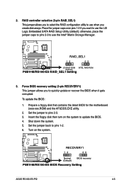
... floppy disk then turn on the system. ® P5BV-M/RS100-E5 RECOVERY1 12 23 Normal (Default) BIOS recovery P5BV-M/RS100-E5 BIOS Recovery Setting ASUS RS100-E5-PI2 4-5 Turn on the system to use the Intel® Matrix Storage Manager. ® P5BV-M/RS100-E5 RAID_SEL1 12 23 LSI RAID ROM INTEL RAID ROM (Default) P5BV-M/RS100-E5 RAID_SEL1 Setting 3. otherwise, place the jumper caps to...
... floppy disk then turn on the system. ® P5BV-M/RS100-E5 RECOVERY1 12 23 Normal (Default) BIOS recovery P5BV-M/RS100-E5 BIOS Recovery Setting ASUS RS100-E5-PI2 4-5 Turn on the system to use the Intel® Matrix Storage Manager. ® P5BV-M/RS100-E5 RAID_SEL1 12 23 LSI RAID ROM INTEL RAID ROM (Default) P5BV-M/RS100-E5 RAID_SEL1 Setting 3. otherwise, place the jumper caps to...
User Guide
Page 52
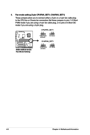
CHAFAN_SET1) These jumpers allow you to connect either a 3-pin or a 4-pin fan cable plug to the CPU fan or Chasis fan connectors Set these jumpers to pins 1-2 Short PWM mode if you are using a 4-pin fan cable plug, or to pins 2‑3 Short DC mode if you are using a 3-pin plug. ® P5BV-M/RS100-E5 P5BV-M/RS100-E5 Fan Mode Setting CPUFAN_SET1 12 23 PWM Mode (Default) DC Mode CHAFAN_SET1 12 23 PWM Mode (Default) DC Mode 4-6 Chapter 4: Motherboard Information Fan mode setting (3-pin CPUFAN_SET1; 4.
CHAFAN_SET1) These jumpers allow you to connect either a 3-pin or a 4-pin fan cable plug to the CPU fan or Chasis fan connectors Set these jumpers to pins 1-2 Short PWM mode if you are using a 4-pin fan cable plug, or to pins 2‑3 Short DC mode if you are using a 3-pin plug. ® P5BV-M/RS100-E5 P5BV-M/RS100-E5 Fan Mode Setting CPUFAN_SET1 12 23 PWM Mode (Default) DC Mode CHAFAN_SET1 12 23 PWM Mode (Default) DC Mode 4-6 Chapter 4: Motherboard Information Fan mode setting (3-pin CPUFAN_SET1; 4.
User Guide
Page 54
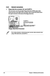
P5BV-M/RS100-E5 Floppy Disk Drive Connector Pin 5 on the floppy ribbon cable to prevent incorrect cable connection when using a FDD cable with a covered Pin 5. 4-8 Chapter 4: Motherboard Information ... end of the cable to this connector, then connect the other end to the signal connector at the back of the floppy disk drive. ® P5BV-M/RS100-E5 FLOPPY1 PIN1 NOTE: Orient the red markings on the connector is for the provided Floppy Disk Drive (FDD) signal cable. 4.3.2 Internal connectors 1.
P5BV-M/RS100-E5 Floppy Disk Drive Connector Pin 5 on the floppy ribbon cable to prevent incorrect cable connection when using a FDD cable with a covered Pin 5. 4-8 Chapter 4: Motherboard Information ... end of the cable to this connector, then connect the other end to the signal connector at the back of the floppy disk drive. ® P5BV-M/RS100-E5 FLOPPY1 PIN1 NOTE: Orient the red markings on the connector is for the provided Floppy Disk Drive (FDD) signal cable. 4.3.2 Internal connectors 1.
User Guide
Page 55
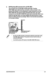
... drive as a slave device by setting its jumper accordingly. ASUS RS100-E5-PI2 4-9 ICH7R primary IDE connector (40-1 pin PRI_IDE1) This connector is removed to the hard disk documentation for an Ultra DMA 100/66 IDE master device (hard disk drive). PRI_IDE1 ® P5BV-M/RS100-E5 PIN 1 P5BV-M/RS100-E5 IDE Connector NOTE: Orient the red markings (usually zigzag...
... drive as a slave device by setting its jumper accordingly. ASUS RS100-E5-PI2 4-9 ICH7R primary IDE connector (40-1 pin PRI_IDE1) This connector is removed to the hard disk documentation for an Ultra DMA 100/66 IDE master device (hard disk drive). PRI_IDE1 ® P5BV-M/RS100-E5 PIN 1 P5BV-M/RS100-E5 IDE Connector NOTE: Orient the red markings (usually zigzag...
User Guide
Page 56
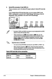
...® Matrix Storage Technology or the LSI MegaRAID® utility embedded in the Intel® ICH7R Southbridge. ® P5BV-M/RS100-E5 SATA3 SATA1 SATA2 SATA4 GND RSATA_RXN2 RSATA_RXP2 GND RSATA_TXN2 RSATA_TXP2 GND GND RSATA_RXN1 RSATA_RXP1 GND RSATA_TXN1 RSATA_TXP1 GND GND RSATA_RXN3 RSATA_RXP3... GND RSATA_TXN3 RSATA_TXP3 GND GND RSATA_RXN4 RSATA_RXP4 GND RSATA_TXN4 RSATA_TXP4 GND P5BV-M/RS100-E5 SATA Connectors • By default, SATA1 and SATA3 connectors are pre-installed with two SATA cables for each RAID...
...® Matrix Storage Technology or the LSI MegaRAID® utility embedded in the Intel® ICH7R Southbridge. ® P5BV-M/RS100-E5 SATA3 SATA1 SATA2 SATA4 GND RSATA_RXN2 RSATA_RXP2 GND RSATA_TXN2 RSATA_TXP2 GND GND RSATA_RXN1 RSATA_RXP1 GND RSATA_TXN1 RSATA_TXP1 GND GND RSATA_RXN3 RSATA_RXP3... GND RSATA_TXN3 RSATA_TXP3 GND GND RSATA_RXN4 RSATA_RXP4 GND RSATA_TXN4 RSATA_TXP4 GND P5BV-M/RS100-E5 SATA Connectors • By default, SATA1 and SATA3 connectors are pre-installed with two SATA cables for each RAID...
User Guide
Page 57
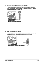
... Mbps connection speed. USB connector (10-1 pin USB34) This connector is for USB 2.0 ports. USB+5V USB_P3USB_P3+ GND ® P5BV-M/RS100-E5 USB34 P5BV-M/RS100-E5 USB 2.0 Connector USB+5V USB_P4USB_P4+ GND NC ASUS RS100-E5-PI2 4-11 HDLED1 1 ® P5BV-M/RS100-E5 P5BV-M/RS100-E5 Hard Disk Activity LED Connector 5. This USB connector complies with USB 2.0 specification that supports up . The read or write...
... Mbps connection speed. USB connector (10-1 pin USB34) This connector is for USB 2.0 ports. USB+5V USB_P3USB_P3+ GND ® P5BV-M/RS100-E5 USB34 P5BV-M/RS100-E5 USB 2.0 Connector USB+5V USB_P4USB_P4+ GND NC ASUS RS100-E5-PI2 4-11 HDLED1 1 ® P5BV-M/RS100-E5 P5BV-M/RS100-E5 Hard Disk Activity LED Connector 5. This USB connector complies with USB 2.0 specification that supports up . The read or write...
User Guide
Page 58
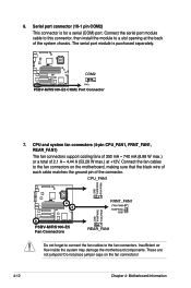
... fan cables to the fan connectors on the fan connectors! 4-12 Chapter 4: Motherboard Information CPU_FAN1 GND FANPWR2 FAN PWM ® P5BV-M/RS100-E5 FRNT_FAN1 FAN PWM FANPWR2 GND GND FANPWR2 FAN PWM P5BV-M/RS100-E5 Fan Connectors REAR_FAN1 Do not forget to connect the fan cables to a slot opening at +12V. Do not place jumper caps...fan connectors. Insufficient air flow inside the system may damage the motherboard components. Serial port connector (10-1 pin COM2) This connector is purchased separately. ® P5BV-M/RS100-E5 COM2 PIN 1 P5BV-M/RS100-E5 COM2 Port Connector 7.
... fan cables to the fan connectors on the fan connectors! 4-12 Chapter 4: Motherboard Information CPU_FAN1 GND FANPWR2 FAN PWM ® P5BV-M/RS100-E5 FRNT_FAN1 FAN PWM FANPWR2 GND GND FANPWR2 FAN PWM P5BV-M/RS100-E5 Fan Connectors REAR_FAN1 Do not forget to connect the fan cables to a slot opening at +12V. Do not place jumper caps...fan connectors. Insufficient air flow inside the system may damage the motherboard components. Serial port connector (10-1 pin COM2) This connector is purchased separately. ® P5BV-M/RS100-E5 COM2 PIN 1 P5BV-M/RS100-E5 COM2 Port Connector 7.
User Guide
Page 59
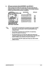
...Volts Ground Power OK +5V Standby +12 Volts +12 Volts +3 Volts GND GND ® P5BV-M/RS100-E5 +3 Volts -12 Volts Ground PSON# Ground Ground Ground -5 Volts +5 Volts +5 Volts +5 Volts Ground +12V DC +12V DC P5BV-M/RS100-E5 ATX Power Connector • Use of 450 W is inadequate. • You must install ...power connectors (24-pin EATXPWR1, 4-pin ATX12V1) These connectors are designed to connect the 4-pin or 8-pin ATX +12 V power plug; ASUS RS100-E5-PI2 4-13 The power supply plugs are for a fullyconfigured system. • Do not forget to fit these connectors in only one orientation....
...Volts Ground Power OK +5V Standby +12 Volts +12 Volts +3 Volts GND GND ® P5BV-M/RS100-E5 +3 Volts -12 Volts Ground PSON# Ground Ground Ground -5 Volts +5 Volts +5 Volts +5 Volts Ground +12V DC +12V DC P5BV-M/RS100-E5 ATX Power Connector • Use of 450 W is inadequate. • You must install ...power connectors (24-pin EATXPWR1, 4-pin ATX12V1) These connectors are designed to connect the 4-pin or 8-pin ATX +12 V power plug; ASUS RS100-E5-PI2 4-13 The power supply plugs are for a fullyconfigured system. • Do not forget to fit these connectors in only one orientation....
User Guide
Page 60
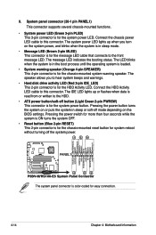
... the system is in sleep or soft-off the system power. 1 2 3 POWERLED+ GND POWERLEDMLED+ MLEDNC +5V GND GND SPKROUT ® P5BV-M/RS100-E5 PANEL1 HDLED+ HDLEDNMIBTN# GND POWERBTN# GND NC RESETBTN# GND 4 5 6 P5BV-M/RS100-E5 System Panel Connector The system panel connector is for the system power button. 9. The IDE LED lights up when you to...
... the system is in sleep or soft-off the system power. 1 2 3 POWERLED+ GND POWERLEDMLED+ MLEDNC +5V GND GND SPKROUT ® P5BV-M/RS100-E5 PANEL1 HDLED+ HDLEDNMIBTN# GND POWERBTN# GND NC RESETBTN# GND 4 5 6 P5BV-M/RS100-E5 System Panel Connector The system panel connector is for the system power button. 9. The IDE LED lights up when you to...