
User Guide
Page 6
... 7.2.2 Red Hat® Enterprise 7-15 7.3 VGA driver installation 7-16 7.3.1 Windows® Server 7-16 7.3.2 Red Hat enterprise 7-17 7.4 Management applications and utilities installation 7-18 7.4.1 Running the support CD 7-18 7.4.2 Drivers menu 7-18 7.4.3 Management Software menu 7-19 7.4.4 Utilities menu 7-19 7.4.5 Contact information 7-20 Appendix: Reference information A.1 Intel® EM64T A-2 Using the Intel®...
... 7.2.2 Red Hat® Enterprise 7-15 7.3 VGA driver installation 7-16 7.3.1 Windows® Server 7-16 7.3.2 Red Hat enterprise 7-17 7.4 Management applications and utilities installation 7-18 7.4.1 Running the support CD 7-18 7.4.2 Drivers menu 7-18 7.4.3 Management Software menu 7-19 7.4.4 Utilities menu 7-19 7.4.5 Contact information 7-20 Appendix: Reference information A.1 Intel® EM64T A-2 Using the Intel®...

User Guide
Page 12
... 1 x 220W 80+ Single Power Supply 2 x SATA Cables 1 x PCI Express x16 Riser Card (x8 link) 1 x Front I/O Board (ASUS FPB-R9) 1 x USB Board (ASUS USB-R9) 2 x System Fans (2 x 40x28) 1 x CPU Heatsink 1 x RS100-E5-PI2 User's Guide 1 x ASUS ASWM 2.0 User's Guide 1 x RS100-E5-PI2 Support CD (including ASWM*) 1 x Bag of Screws 1 x AC Power Cable Rackmount Rail Kit Slim-type Optical Device...
... 1 x 220W 80+ Single Power Supply 2 x SATA Cables 1 x PCI Express x16 Riser Card (x8 link) 1 x Front I/O Board (ASUS FPB-R9) 1 x USB Board (ASUS USB-R9) 2 x System Fans (2 x 40x28) 1 x CPU Heatsink 1 x RS100-E5-PI2 User's Guide 1 x ASUS ASWM 2.0 User's Guide 1 x RS100-E5-PI2 Support CD (including ASWM*) 1 x Bag of Screws 1 x AC Power Cable Rackmount Rail Kit Slim-type Optical Device...
User Guide
Page 13
... (Front x 2, Rear x 2) 1 x VGA port 1 x PS/2 keyboard port 1 x PS/2 mouse port (continued on the next page) ASUS RS100-E5-PI2 1-3 Supports software RAID 0 & 1 2 x Internal SATA2 HDD Bays 2 x Broadcom® BCM5721 PCI-E GbE LAN - Model Name Processor / System Bus Core Logic ASUS Features Smart Fan ASWM2.0 Total Slots Memory Capacity Memory Type Memory Size Total PCI/PCI...
... (Front x 2, Rear x 2) 1 x VGA port 1 x PS/2 keyboard port 1 x PS/2 mouse port (continued on the next page) ASUS RS100-E5-PI2 1-3 Supports software RAID 0 & 1 2 x Internal SATA2 HDD Bays 2 x Broadcom® BCM5721 PCI-E GbE LAN - Model Name Processor / System Bus Core Logic ASUS Features Smart Fan ASWM2.0 Total Slots Memory Capacity Memory Type Memory Size Total PCI/PCI...
User Guide
Page 26
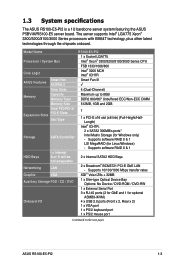
... the heatsink grill is parallel to the Appendix for more information on the socket and damaging the CPU! 6. To install the CPU heatsink: 1. B The motherboard supports Intel® Xeon® 3300/3200/3100/3000 series processors with the heatsink standoffs. The CPU fits in only one correct orientation. Screws Chassis fans...
... the heatsink grill is parallel to the Appendix for more information on the socket and damaging the CPU! 6. To install the CPU heatsink: 1. B The motherboard supports Intel® Xeon® 3300/3200/3100/3000 series processors with the heatsink standoffs. The CPU fits in only one correct orientation. Screws Chassis fans...
User Guide
Page 29
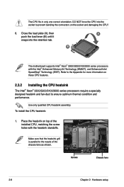
... 2 1 1 2. 2.4.3 Installing a DIMM Unplug the power supply before adding or removing DIMMs or other system components. Failure to do not support DDR DIMMs. DO NOT install DDR DIMMs to the DDR2 DIMM sockets. 2.4.4 Removing a DIMM Follow these steps to unlock the DIMM. Firmly ...avoid damaging the DIMM. • The DDR2 DIMM sockets do so can cause severe damage to both the motherboard and the components. DDR2 DIMM notch ASUS RS100-E5-PI2 2-11 Simultaneously press the retaining clips outward to remove a DIMM. 1. Unlock a DIMM socket by pressing the retaining clips outward. 2. To...
... 2 1 1 2. 2.4.3 Installing a DIMM Unplug the power supply before adding or removing DIMMs or other system components. Failure to do not support DDR DIMMs. DO NOT install DDR DIMMs to the DDR2 DIMM sockets. 2.4.4 Removing a DIMM Follow these steps to unlock the DIMM. Firmly ...avoid damaging the DIMM. • The DDR2 DIMM sockets do so can cause severe damage to both the motherboard and the components. DDR2 DIMM notch ASUS RS100-E5-PI2 2-11 Simultaneously press the retaining clips outward to remove a DIMM. 1. Unlock a DIMM socket by pressing the retaining clips outward. 2. To...

User Guide
Page 43
Get one side for installation. 3. ASUS RS100-E5-PI2 3-7 Secure the rack ear to attach the other rack ear. Locate the six screw holes on each front-side of twelve (12) screws. 2. Orient ... chassis. Prepare the pair of long rack ears and set of the chassis.Select one long rack ear and match the six screw holes to support the server system in a rack cabinet.
Get one side for installation. 3. ASUS RS100-E5-PI2 3-7 Secure the rack ear to attach the other rack ear. Locate the six screw holes on each front-side of twelve (12) screws. 2. Orient ... chassis. Prepare the pair of long rack ears and set of the chassis.Select one long rack ear and match the six screw holes to support the server system in a rack cabinet.
User Guide
Page 57
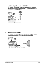
... that supports up to light up. NC ADD_IN_CARD_ACT# ADD_IN_CARD_ACT# NC 4. Hard disk activity LED connector (4-pin HDLED1) This connector supplies power to the hard disk activity LED. HDLED1 1 ® P5BV-M/RS100-E5 P5BV-M/RS100-E5 Hard Disk Activity LED Connector 5. USB+5V USB_P3USB_P3+ GND ® P5BV-M/RS100-E5 USB34 P5BV-M/RS100-E5 USB 2.0 Connector USB+5V USB_P4USB_P4+ GND NC ASUS RS100-E5...
... that supports up to light up. NC ADD_IN_CARD_ACT# ADD_IN_CARD_ACT# NC 4. Hard disk activity LED connector (4-pin HDLED1) This connector supplies power to the hard disk activity LED. HDLED1 1 ® P5BV-M/RS100-E5 P5BV-M/RS100-E5 Hard Disk Activity LED Connector 5. USB+5V USB_P3USB_P3+ GND ® P5BV-M/RS100-E5 USB34 P5BV-M/RS100-E5 USB 2.0 Connector USB+5V USB_P4USB_P4+ GND NC ASUS RS100-E5...
User Guide
Page 58
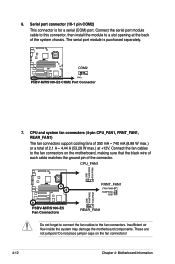
...RS100-E5 Fan Connectors REAR_FAN1 Do not forget to connect the fan cables to a slot opening at +12V. These are not jumpers! Insufficient air flow inside the system may damage the motherboard components. CPU and system fan connectors (4-pin CPU_FAN1, FRNT_FAN1, REAR_FAN1) The fan connectors support...12 Chapter 4: Motherboard Information 6. Serial port connector (10-1 pin COM2) This connector is purchased separately. ® P5BV-M/RS100-E5 COM2 PIN 1 P5BV-M/RS100-E5 COM2 Port Connector 7. Do not place jumper caps on the motherboard, making sure that the black wire of each cable ...
...RS100-E5 Fan Connectors REAR_FAN1 Do not forget to connect the fan cables to a slot opening at +12V. These are not jumpers! Insufficient air flow inside the system may damage the motherboard components. CPU and system fan connectors (4-pin CPU_FAN1, FRNT_FAN1, REAR_FAN1) The fan connectors support...12 Chapter 4: Motherboard Information 6. Serial port connector (10-1 pin COM2) This connector is purchased separately. ® P5BV-M/RS100-E5 COM2 PIN 1 P5BV-M/RS100-E5 COM2 Port Connector 7. Do not place jumper caps on the motherboard, making sure that the black wire of each cable ...
User Guide
Page 60
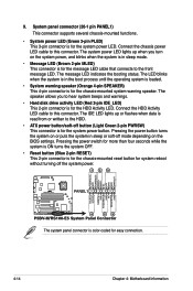
...supports several chassis-mounted functions. • System power LED (Green 3-pin PLED) This 3-pin connector is for the system power LED. The LED blinks when the system is in sleep or soft-off the system power. 1 2 3 POWERLED+ GND POWERLEDMLED+ MLEDNC +5V GND GND SPKROUT ® P5BV-M/RS100-E5... PANEL1 HDLED+ HDLEDNMIBTN# GND POWERBTN# GND NC RESETBTN# GND 4 5 6 P5BV-M/RS100-E5 System Panel Connector The system panel connector is for the HDD Activity LED.
...supports several chassis-mounted functions. • System power LED (Green 3-pin PLED) This 3-pin connector is for the system power LED. The LED blinks when the system is in sleep or soft-off the system power. 1 2 3 POWERLED+ GND POWERLEDMLED+ MLEDNC +5V GND GND SPKROUT ® P5BV-M/RS100-E5... PANEL1 HDLED+ HDLEDNMIBTN# GND POWERBTN# GND NC RESETBTN# GND 4 5 6 P5BV-M/RS100-E5 System Panel Connector The system panel connector is for the HDD Activity LED.

User Guide
Page 61
...-2 pin AUX_PANEL1) This connector supports several server system functions. AUX_PANEL1 1 22 ® P5BV-M/RS100-E5 NC I2CCLK1 GND I2CDATA1 +5VSB LAN1_LINKACTLEDLAN1_LINKACTLED+ LAN2_LINKACTLED+ LAN2_LINKACTLED- +5VSB CASEOPEN GND LOCATORLED1+ LOCATORLED1LOCATORBTN# GND LOCAT ORLED2LOCATORLED2+ P5BV-M/RS100-E5 Auxiliary Panel Connector 3 454 ...LED (2-pin LOCATORLED1 and 2-pin LOCATORLED2) These leads are for a chassis with an intrusion detection feature. ASUS RS100-E5-PI2 4-15 This requires an external detection mechanism such as a chassis intrusion sensor or microswitch. The LEDs...
...-2 pin AUX_PANEL1) This connector supports several server system functions. AUX_PANEL1 1 22 ® P5BV-M/RS100-E5 NC I2CCLK1 GND I2CDATA1 +5VSB LAN1_LINKACTLEDLAN1_LINKACTLED+ LAN2_LINKACTLED+ LAN2_LINKACTLED- +5VSB CASEOPEN GND LOCATORLED1+ LOCATORLED1LOCATORBTN# GND LOCAT ORLED2LOCATORLED2+ P5BV-M/RS100-E5 Auxiliary Panel Connector 3 454 ...LED (2-pin LOCATORLED1 and 2-pin LOCATORLED2) These leads are for a chassis with an intrusion detection feature. ASUS RS100-E5-PI2 4-15 This requires an external detection mechanism such as a chassis intrusion sensor or microswitch. The LEDs...
User Guide
Page 65
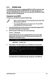
... support CD to the bootable floppy disk you to save the file. • The succeeding BIOS screens are for the extension name. The utility copies the current BIOS file to file...... 5.1.2 AFUDOS utility The AFUDOS utility allows you created earlier. 2. Version 1.19(ASUS V2...current BIOS To copy the current BIOS file using a bootable floppy disk with the updated BIOS file. done Write to the floppy disk. ASUS RS100-E5-PI2 5-3 A:\>afudos /oOLDBIOS1.rom AMI Firmware Update Utility - All rights reserved. Reading flash ..... ok A:\> The utility returns to copy the...
... support CD to the bootable floppy disk you to save the file. • The succeeding BIOS screens are for the extension name. The utility copies the current BIOS file to file...... 5.1.2 AFUDOS utility The AFUDOS utility allows you created earlier. 2. Version 1.19(ASUS V2...current BIOS To copy the current BIOS file using a bootable floppy disk with the updated BIOS file. done Write to the floppy disk. ASUS RS100-E5-PI2 5-3 A:\>afudos /oOLDBIOS1.rom AMI Firmware Update Utility - All rights reserved. Reading flash ..... ok A:\> The utility returns to copy the...
User Guide
Page 66
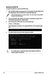
... in DOS mode, then at the DOS prompt. 2. Copy the AFUDOS utility (afudos.exe) from the motherboard support CD to prevent system boot failure! 5-4 Chapter 5: BIOS setup Version 1.19(ASUS V2.07(03.11.24BB)) Copyright (C) 2002 American Megatrends, Inc. done Reading flash ...... A:\>afudos /irs100e5.rom... AMI Firmware Update Utility - Visit the ASUS website (www.asus.com) and download the latest BIOS file for the motherboard. Save the BIOS file to type the exact BIOS filename at the ...
... in DOS mode, then at the DOS prompt. 2. Copy the AFUDOS utility (afudos.exe) from the motherboard support CD to prevent system boot failure! 5-4 Chapter 5: BIOS setup Version 1.19(ASUS V2.07(03.11.24BB)) Copyright (C) 2002 American Megatrends, Inc. done Reading flash ...... A:\>afudos /irs100e5.rom... AMI Firmware Update Utility - Visit the ASUS website (www.asus.com) and download the latest BIOS file for the motherboard. Save the BIOS file to type the exact BIOS filename at the ...
User Guide
Page 67
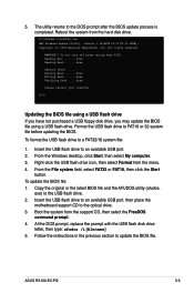
... click the Start button. done Reading flash ...... Right-click the USB flash drive icon, then select Format from the support CD, then select the FreeDOS command prompt. 4. ASUS RS100-E5-PI2 5-5 A:\>afudos /irs100e5.rom AMI Firmware Update Utility - Do not turn off power during flash BIOS Reading file ... the latest BIOS file and the AFUDOS utility (afudos. Insert the USB flash drive to an available USB port, then place the motherboard support CD to the USB flash drive. 2. Boot the system from the menu. 4. done Please restart your computer A:\> Updating the BIOS file...
... click the Start button. done Reading flash ...... Right-click the USB flash drive icon, then select Format from the support CD, then select the FreeDOS command prompt. 4. ASUS RS100-E5-PI2 5-5 A:\>afudos /irs100e5.rom AMI Firmware Update Utility - Do not turn off power during flash BIOS Reading file ... the latest BIOS file and the AFUDOS utility (afudos. Insert the USB flash drive to an available USB port, then place the motherboard support CD to the USB flash drive. 2. Boot the system from the menu. 4. done Please restart your computer A:\> Updating the BIOS file...
User Guide
Page 68
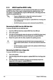
... utility completes the updating process. • Only the USB flash disk with the original or updated BIOS file to the USB port. 2. You can support ASUS CrashFree BIOS 3. Insert the USB flash disk that contains BIOS file to the floppy disk drive. 3. Doing so can cause system boot failure! Bad ...recovery tool that allows you rename the original or updated BIOS file in the floppy disk or the USB flash disk. • Visit ASUS website (www.asus.com) to restore the BIOS file when it fails or gets corrupted during the updating process. The utility will automatically checks the devices ...
... utility completes the updating process. • Only the USB flash disk with the original or updated BIOS file to the USB port. 2. You can support ASUS CrashFree BIOS 3. Insert the USB flash disk that contains BIOS file to the floppy disk drive. 3. Doing so can cause system boot failure! Bad ...recovery tool that allows you rename the original or updated BIOS file in the floppy disk or the USB flash disk. • Visit ASUS website (www.asus.com) to restore the BIOS file when it fails or gets corrupted during the updating process. The utility will automatically checks the devices ...
User Guide
Page 70
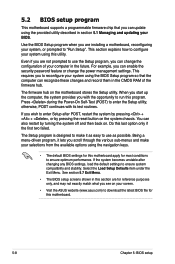
...only, and may not exactly match what you see on the system chassis. If you to configure your screen. • Visit the ASUS website (www.asus.com) to enter Setup after changing any BIOS settings, load the default settings to enter the Setup utility; For example, you can ...in section 5.1 Managing and updating your computer in the future. 5.2 BIOS setup program This motherboard supports a programmable firmware chip that the computer can recognize these changes and record them in the CMOS RAM of your BIOS. Use the BIOS Setup program when you are not prompted to "Run Setup"....
...only, and may not exactly match what you see on the system chassis. If you to configure your screen. • Visit the ASUS website (www.asus.com) to enter Setup after changing any BIOS settings, load the default settings to enter the Setup utility; For example, you can ...in section 5.1 Managing and updating your computer in the future. 5.2 BIOS setup program This motherboard supports a programmable firmware chip that the computer can recognize these changes and record them in the CMOS RAM of your BIOS. Use the BIOS Setup program when you are not prompted to "Run Setup"....
User Guide
Page 74
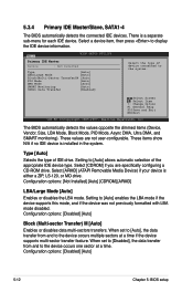
...display the IDE device information. When set to [Disabled], the data transfer from and to the device occurs one sector at a time if the device supports multi-sector transfer feature. Configuration options: [Disabled] [Auto] 5-12 Chapter 5: BIOS setup There is a separate sub-menu for each IDE device. ...Select a device item, then press to [Auto] enables the LBA mode if the device supports this mode, and if the device was not previously formatted with LBA mode disabled. Main BIOS SETUP UTILITY Primary IDE Master Device : Not Detected...
...display the IDE device information. When set to [Disabled], the data transfer from and to the device occurs one sector at a time if the device supports multi-sector transfer feature. Configuration options: [Disabled] [Auto] 5-12 Chapter 5: BIOS setup There is a separate sub-menu for each IDE device. ...Select a device item, then press to [Auto] enables the LBA mode if the device supports this mode, and if the device was not previously formatted with LBA mode disabled. Main BIOS SETUP UTILITY Primary IDE Master Device : Not Detected...
User Guide
Page 78
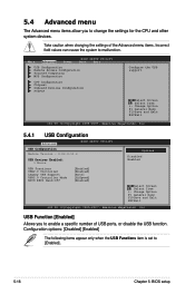
... Configuration Advanced BIOS SETUP UTILITY USB Configuration Module Version - 2.24.3-13.4 USB Devices Enabled: 1 Mouse USB Functions USB2.0 Controller Legacy USB Support USB2.0 Controller Mode BIOS EHCI Hand-Off [Enabled] [Enabled] [Auto] [HiSpeed] [Enabled] Options Disabled Enabled Select Screen Select Item ...USB Configuration Remote Access Configuration Trusted Computing MPS Configuration CPU Configuration Chipset Onboard Devices Configuration PCIPnP Configure the USB support. Change Option F1 General Help F10 Save and Exit ESC Exit v02.58 (C)Copyright 1985-2007, American Megatrends...
... Configuration Advanced BIOS SETUP UTILITY USB Configuration Module Version - 2.24.3-13.4 USB Devices Enabled: 1 Mouse USB Functions USB2.0 Controller Legacy USB Support USB2.0 Controller Mode BIOS EHCI Hand-Off [Enabled] [Enabled] [Auto] [HiSpeed] [Enabled] Options Disabled Enabled Select Screen Select Item ...USB Configuration Remote Access Configuration Trusted Computing MPS Configuration CPU Configuration Chipset Onboard Devices Configuration PCIPnP Configure the USB support. Change Option F1 General Help F10 Save and Exit ESC Exit v02.58 (C)Copyright 1985-2007, American Megatrends...
User Guide
Page 79
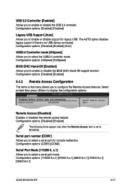
...Controller mode [HiSpeed] Allows you to enable or disable support for console redirection. Serial port number [COM1] Allows you to select a serial port mode. Configuration options: [115200 8,n,1] [57600 8,n,1] [38400 8,n,1] [19200 8,n,1] [09600 8,n,1] ASUS RS100-E5-PI2 5-17 Remote Access [Disabled] Enables or disables the...UTILITY Configure Remote Access type and parameters Remote Access [Disabled] Select Remote Access type. The AUTO option disables legacy support if there is set to [Enabled]. Configuration options: [HiSpeed] [FullSpeed] BIOS EHCI Hand-Off [Enabled] Allows...
...Controller mode [HiSpeed] Allows you to enable or disable support for console redirection. Serial port number [COM1] Allows you to select a serial port mode. Configuration options: [115200 8,n,1] [57600 8,n,1] [38400 8,n,1] [19200 8,n,1] [09600 8,n,1] ASUS RS100-E5-PI2 5-17 Remote Access [Disabled] Enables or disables the...UTILITY Configure Remote Access type and parameters Remote Access [Disabled] Select Remote Access type. The AUTO option disables legacy support if there is set to [Enabled]. Configuration options: [HiSpeed] [FullSpeed] BIOS EHCI Hand-Off [Enabled] Allows...

User Guide
Page 80
... options: [Enabled] [Disabled] 5.4.3 Trusted Computing Advanced BIOS SETUP UTILITY Trusted Computing TCG/TPM SUPPORT [No] TCG/TPM SUPPORT [No] Allows you to set to select the MPS revision. Some operating systems may not work when this item is set...] Allows you to select the target terminal type. Configuration options: [ANSI] [VT100] [VT-UTF8] VT-UTF8 Combo Key Support [Enabled] Allows you to enable or disable VT-UTF8 Combination Key Support for console redirection. Configuration options: [No] [Yes] Enable/Disable TPM TCG (TPM 1.1/1.2) supp in BIOS 5.4.4 MPS Configuration ...
... options: [Enabled] [Disabled] 5.4.3 Trusted Computing Advanced BIOS SETUP UTILITY Trusted Computing TCG/TPM SUPPORT [No] TCG/TPM SUPPORT [No] Allows you to set to select the MPS revision. Some operating systems may not work when this item is set...] Allows you to select the target terminal type. Configuration options: [ANSI] [VT100] [VT-UTF8] VT-UTF8 Combo Key Support [Enabled] Allows you to enable or disable VT-UTF8 Combination Key Support for console redirection. Configuration options: [No] [Yes] Enable/Disable TPM TCG (TPM 1.1/1.2) supp in BIOS 5.4.4 MPS Configuration ...
User Guide
Page 81
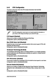
... options: [Disabled] [Enabled] Max CPUID Value Limit [Disabled] Enable this menu show the CPU-related information that cannot support CPUs with extended CPUID functions. Configuration options: [Disabled] [Enabled] Vanderpool Technology [Enabled] The Vanderpool Technology allows a hardware... exactly match the information on your actual CPU type. C1E Support Max CPUID Value Limit: Vanderpool Technology CPU TM function: Execute Disable Bit [Enabled] [Disabled] [Enabled] [Enabled] [Enabled] Select Screen Select Item +- Configuration options: [Disabled] [Enabled] ASUS RS100-E5-PI2 5-19
... options: [Disabled] [Enabled] Max CPUID Value Limit [Disabled] Enable this menu show the CPU-related information that cannot support CPUs with extended CPUID functions. Configuration options: [Disabled] [Enabled] Vanderpool Technology [Enabled] The Vanderpool Technology allows a hardware... exactly match the information on your actual CPU type. C1E Support Max CPUID Value Limit: Vanderpool Technology CPU TM function: Execute Disable Bit [Enabled] [Disabled] [Enabled] [Enabled] [Enabled] Select Screen Select Item +- Configuration options: [Disabled] [Enabled] ASUS RS100-E5-PI2 5-19


