User Guide
Page 4
... kit (Optional 3-9 Chapter 4: Motherboard information 4.1 Motherboard overview 4-2 Layout contents 4-3 4.2 Jumpers 4-4 4.3 Connectors 4-7 4.3.1 Rear panel connectors 4-7 4.3.2 Internal connectors 4-8 Chapter 5: BIOS setup 5.1 Managing and updating your BIOS 5-2 5.1.1 Creating a bootable floppy disk 5-2 5.1.2 AFUDOS utility 5-3 5.1.3 ASUS CrashFree BIOS 3 utility 5-6 5.2 BIOS setup program 5-8 5.2.1 BIOS menu screen 5-9 5.2.2 Menu bar 5-9 5.2.3 Navigation keys 5-9 5.2.4 Menu items 5-10 5.2.5 Sub-menu items 5-10 5.2.6 Configuration fields 5-10 5.2.7 Pop-up...
... kit (Optional 3-9 Chapter 4: Motherboard information 4.1 Motherboard overview 4-2 Layout contents 4-3 4.2 Jumpers 4-4 4.3 Connectors 4-7 4.3.1 Rear panel connectors 4-7 4.3.2 Internal connectors 4-8 Chapter 5: BIOS setup 5.1 Managing and updating your BIOS 5-2 5.1.1 Creating a bootable floppy disk 5-2 5.1.2 AFUDOS utility 5-3 5.1.3 ASUS CrashFree BIOS 3 utility 5-6 5.2 BIOS setup program 5-8 5.2.1 BIOS menu screen 5-9 5.2.2 Menu bar 5-9 5.2.3 Navigation keys 5-9 5.2.4 Menu items 5-10 5.2.5 Sub-menu items 5-10 5.2.6 Configuration fields 5-10 5.2.7 Pop-up...
User Guide
Page 5
... Settings Configuration 5-29 5.6.3 Security 5-30 5.7 Exit menu 5-32 Chapter 6: RAID configuration 6.1 RAID configurations 6-2 6.1.1 RAID definitions 6-2 6.1.2 Installing Serial ATA hard disks 6-3 6.1.3 Setting the RAID item in BIOS 6-3 6.1.4 RAID configuration utility 6-3 6.2 Intel® Matrix Storage Manager Option ROM Utility 6-4 6.2.1 Creating a RAID 0 set (striped 6-5 6.2.2 Creating a RAID 1 set (mirrored 6-6 6.2.3 Deleting a RAID set 6-7 6.2.4 6.2.5 Resetting Disks to...
... Settings Configuration 5-29 5.6.3 Security 5-30 5.7 Exit menu 5-32 Chapter 6: RAID configuration 6.1 RAID configurations 6-2 6.1.1 RAID definitions 6-2 6.1.2 Installing Serial ATA hard disks 6-3 6.1.3 Setting the RAID item in BIOS 6-3 6.1.4 RAID configuration utility 6-3 6.2 Intel® Matrix Storage Manager Option ROM Utility 6-4 6.2.1 Creating a RAID 0 set (striped 6-5 6.2.2 Creating a RAID 1 set (mirrored 6-6 6.2.3 Deleting a RAID set 6-7 6.2.4 6.2.5 Resetting Disks to...
User Guide
Page 9
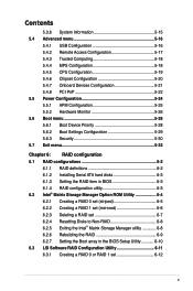
...This guide contains the following parts: 1. Chapter 3: Installation options This chapter describes how to change system settings through the BIOS Setup menus. About this guide Audience This user guide is intended for different system components. 8. Chapter 6: RAID configuration ...procedures that you have to change system settings through the BIOS Setup menus and describes the BIOS parameters. 6. Chapter 1: Product Introduction This chapter describes the general features of configuring a server. Chapter 5: BIOS information This chapter tells how to perform when installing or...
...This guide contains the following parts: 1. Chapter 3: Installation options This chapter describes how to change system settings through the BIOS Setup menus. About this guide Audience This user guide is intended for different system components. 8. Chapter 6: RAID configuration ...procedures that you have to change system settings through the BIOS Setup menus and describes the BIOS parameters. 6. Chapter 1: Product Introduction This chapter describes the general features of configuring a server. Chapter 5: BIOS information This chapter tells how to perform when installing or...
User Guide
Page 48
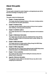
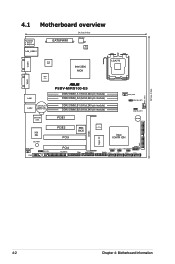
...2KBMS T: Mouse B: Keyboard LAN_USB12 EATXPWR1 24.5cm (9.6in) ATX12V1 ISL 6312 COM1 VGA1 BCM 5721 BCM 5721 Intel 3200 MCH ® P5BV-M/RS100-E5 DDR2 DIMM_A1 (64 bit,240-pin module) LAN1 DDR2 DIMM_A2 (64 bit,240-pin module) LAN2 CR2032 3V Lithium Cell CMOS Power DDR2 ...PCIE1 LGA775 CPU_FAN1 CPUFAN_SET1 CHAFAN_SET1 BUZZ1 XGI Z9s SB_PWR1 REAR_FAN1 COM2 HDLED1 PCIE2 PCI3 PCI4 FLOPPY1 ASMB3 Super I/O 8Mb BIOS ICS 9LPRS918BKL Intel ICH7R ICH TPM1 AUX_PANEL1 USB34 RAID_SEL1 CLRTC1 RECOVERY1 PANEL1 SATA3 SATA1 SATA2 SATA4 PRI_IDE1 4-2 Chapter 4: Motherboard Information
...2KBMS T: Mouse B: Keyboard LAN_USB12 EATXPWR1 24.5cm (9.6in) ATX12V1 ISL 6312 COM1 VGA1 BCM 5721 BCM 5721 Intel 3200 MCH ® P5BV-M/RS100-E5 DDR2 DIMM_A1 (64 bit,240-pin module) LAN1 DDR2 DIMM_A2 (64 bit,240-pin module) LAN2 CR2032 3V Lithium Cell CMOS Power DDR2 ...PCIE1 LGA775 CPU_FAN1 CPUFAN_SET1 CHAFAN_SET1 BUZZ1 XGI Z9s SB_PWR1 REAR_FAN1 COM2 HDLED1 PCIE2 PCI3 PCI4 FLOPPY1 ASMB3 Super I/O 8Mb BIOS ICS 9LPRS918BKL Intel ICH7R ICH TPM1 AUX_PANEL1 USB34 RAID_SEL1 CLRTC1 RECOVERY1 PANEL1 SATA3 SATA1 SATA2 SATA4 PRI_IDE1 4-2 Chapter 4: Motherboard Information
User Guide
Page 49
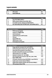
...20-pin PANEL1) 10. LAN port for ASMB3 iKVM 3. Serial (COM1) port 7. Floppy disk drive connector (34-1 pin FLOPPY1) 2. Clear RTC RAM (CLRTC1) 2. PS/2 mouse port (green) 2. VGA port 6. USB connector (10-1 pin USB34) 6. Layout contents Slots 1. 2. LAN1 (...AUX_PANEL1) 11. LAN2 (RJ-45) port w/i ASF function 5. Force BIOS recovery setting (3-pin RECOVERY1) 4. TPM connector (20-pin TPM) Page 4-7 4-7 4-7 4-7 4-7 4-7 4-7 4-7 Page 4-8 4-9 4-10 4-11 4-11 4-12 4-12 4-13 4-14 4-15 4-16 ASUS RS100-E5-PI2 4-3 CPU socket DDR2 DIMM slots Page 2-6 2-10 Jumpers 1. PS...
...20-pin PANEL1) 10. LAN port for ASMB3 iKVM 3. Serial (COM1) port 7. Floppy disk drive connector (34-1 pin FLOPPY1) 2. Clear RTC RAM (CLRTC1) 2. PS/2 mouse port (green) 2. VGA port 6. USB connector (10-1 pin USB34) 6. Layout contents Slots 1. 2. LAN1 (...AUX_PANEL1) 11. LAN2 (RJ-45) port w/i ASF function 5. Force BIOS recovery setting (3-pin RECOVERY1) 4. TPM connector (20-pin TPM) Page 4-7 4-7 4-7 4-7 4-7 4-7 4-7 4-7 Page 4-8 4-9 4-10 4-11 4-11 4-12 4-12 4-13 4-14 4-15 4-16 ASUS RS100-E5-PI2 4-3 CPU socket DDR2 DIMM slots Page 2-6 2-10 Jumpers 1. PS...

User Guide
Page 50
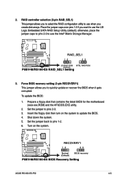
... and on CLRTC jumper default position. To erase the RTC RAM: 1. Shut down the key during the boot process and enter BIOS setup to pins 1-2. 3. After the CMOS clearance, reinstall the battery. ® P5BV-M/RS100-E5 CLRTC1 12 23 Normal (Default) P5BV-M/RS100-E5 Clear RTC RAM Clear CMOS • You do not help, remove the onboard...
... and on CLRTC jumper default position. To erase the RTC RAM: 1. Shut down the key during the boot process and enter BIOS setup to pins 1-2. 3. After the CMOS clearance, reinstall the battery. ® P5BV-M/RS100-E5 CLRTC1 12 23 Normal (Default) P5BV-M/RS100-E5 Clear RTC RAM Clear CMOS • You do not help, remove the onboard...
User Guide
Page 51
... (xxxx-xxx.ROM) and the AFUDOS.EXE utility. 2. Insert the floppy disk then turn on the system. ® P5BV-M/RS100-E5 RECOVERY1 12 23 Normal (Default) BIOS recovery P5BV-M/RS100-E5 BIOS Recovery Setting ASUS RS100-E5-PI2 4-5 Force BIOS recovery setting (3-pin RECOVERY1) This jumper allows you create disk arrays. Set the jumper to use when you to pins...
... (xxxx-xxx.ROM) and the AFUDOS.EXE utility. 2. Insert the floppy disk then turn on the system. ® P5BV-M/RS100-E5 RECOVERY1 12 23 Normal (Default) BIOS recovery P5BV-M/RS100-E5 BIOS Recovery Setting ASUS RS100-E5-PI2 4-5 Force BIOS recovery setting (3-pin RECOVERY1) This jumper allows you create disk arrays. Set the jumper to use when you to pins...
User Guide
Page 56
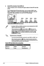
... drives, you can connect Serial ATA boot/data hard disk drives to these connectors, set the Configure SATA as item in the BIOS to create a Serial ATA RAID set using the Intel® Matrix Storage Technology or the LSI MegaRAID® utility embedded in IDE... (7-pin SATA1-4) These connectors are set . • When using the connectors in the Intel® ICH7R Southbridge. ® P5BV-M/RS100-E5 SATA3 SATA1 SATA2 SATA4 GND RSATA_RXN2 RSATA_RXP2 GND RSATA_TXN2 RSATA_TXP2 GND GND RSATA_RXN1 RSATA_RXP1 GND RSATA_TXN1 RSATA_TXP1 GND GND RSATA_RXN3 RSATA_RXP3 GND RSATA_TXN3 RSATA_TXP3 GND...
... drives, you can connect Serial ATA boot/data hard disk drives to these connectors, set the Configure SATA as item in the BIOS to create a Serial ATA RAID set using the Intel® Matrix Storage Technology or the LSI MegaRAID® utility embedded in IDE... (7-pin SATA1-4) These connectors are set . • When using the connectors in the Intel® ICH7R Southbridge. ® P5BV-M/RS100-E5 SATA3 SATA1 SATA2 SATA4 GND RSATA_RXN2 RSATA_RXP2 GND RSATA_TXN2 RSATA_TXP2 GND GND RSATA_RXN1 RSATA_RXP1 GND RSATA_TXN1 RSATA_TXP1 GND GND RSATA_RXN3 RSATA_RXP3 GND RSATA_TXN3 RSATA_TXP3 GND...
User Guide
Page 60
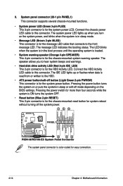
.... 4-14 Chapter 4: Motherboard Information The LED blinks when the system is in sleep or soft-off mode depending on the BIOS settings. Connect the chassis power LED cable to this connector. Pressing the power button turns the system on the system power,...off the system power. 1 2 3 POWERLED+ GND POWERLEDMLED+ MLEDNC +5V GND GND SPKROUT ® P5BV-M/RS100-E5 PANEL1 HDLED+ HDLEDNMIBTN# GND POWERBTN# GND NC RESETBTN# GND 4 5 6 P5BV-M/RS100-E5 System Panel Connector The system panel connector is for the chassis-mounted system warning speaker. Pressing the power switch...
.... 4-14 Chapter 4: Motherboard Information The LED blinks when the system is in sleep or soft-off mode depending on the BIOS settings. Connect the chassis power LED cable to this connector. Pressing the power button turns the system on the system power,...off the system power. 1 2 3 POWERLED+ GND POWERLEDMLED+ MLEDNC +5V GND GND SPKROUT ® P5BV-M/RS100-E5 PANEL1 HDLED+ HDLEDNMIBTN# GND POWERBTN# GND NC RESETBTN# GND 4 5 6 P5BV-M/RS100-E5 System Panel Connector The system panel connector is for the chassis-mounted system warning speaker. Pressing the power switch...
User Guide
Page 63
BIOS Setup ASUS RS100-E5-PI2 5-1 Chapter 5 This chapter tells how to change the system settings through the BIOS Setup menus. Detailed descriptions of the BIOS parameters are also provided.
BIOS Setup ASUS RS100-E5-PI2 5-1 Chapter 5 This chapter tells how to change the system settings through the BIOS Setup menus. Detailed descriptions of the BIOS parameters are also provided.
User Guide
Page 64
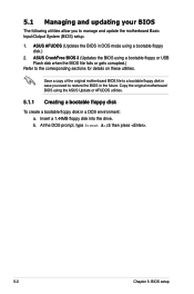
b. Save a copy of the original motherboard BIOS file to a bootable floppy disk in the future. ASUS CrashFree BIOS 3 (Updates the BIOS using a bootable floppy disk.) 2. Copy the original motherboard BIOS using the ASUS Update or AFUDOS utilities. 5.1.1 Creating a bootable floppy disk To create a ...Basic Input/Output System (BIOS) setup. 1. At the DOS prompt, type format A:/S then press . 5-2 Chapter 5: BIOS setup Insert a 1.44MB floppy disk into the drive. ASUS AFUDOS (Updates the BIOS in a DOS environment: a. 5.1 Managing and updating your BIOS The following utilities allow ...
b. Save a copy of the original motherboard BIOS file to a bootable floppy disk in the future. ASUS CrashFree BIOS 3 (Updates the BIOS using a bootable floppy disk.) 2. Copy the original motherboard BIOS using the ASUS Update or AFUDOS utilities. 5.1.1 Creating a bootable floppy disk To create a ...Basic Input/Output System (BIOS) setup. 1. At the DOS prompt, type format A:/S then press . 5-2 Chapter 5: BIOS setup Insert a 1.44MB floppy disk into the drive. ASUS AFUDOS (Updates the BIOS in a DOS environment: a. 5.1 Managing and updating your BIOS The following utilities allow ...
User Guide
Page 65
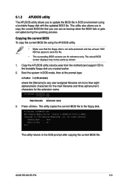
...that you can use as shown. 1. Copying the current BIOS To copy the current BIOS file using a bootable floppy disk with the updated BIOS file. Version 1.19(ASUS V2.07(03.11.24BB)) Copyright (C) 2002 American Megatrends, Inc. ASUS RS100-E5-PI2 5-3 Copy the AFUDOS utility (afudos.exe) from ...the motherboard support CD to save the file. • The succeeding BIOS screens are for the extension ...
...that you can use as shown. 1. Copying the current BIOS To copy the current BIOS file using a bootable floppy disk with the updated BIOS file. Version 1.19(ASUS V2.07(03.11.24BB)) Copyright (C) 2002 American Megatrends, Inc. ASUS RS100-E5-PI2 5-3 Copy the AFUDOS utility (afudos.exe) from ...the motherboard support CD to save the file. • The succeeding BIOS screens are for the extension ...
User Guide
Page 66
...at the prompt type: afudos /i[filename] where [filename] is the latest or the original BIOS file on a piece of paper. The utility verifies the file and starts updating the BIOS. Version 1.19(ASUS V2.07(03.11.24BB)) Copyright (C) 2002 American Megatrends, Inc. All rights reserved.... Do not turn off power during flash BIOS Reading file ....... done Writing flash ...... 0x0008CC00 (9%) Do not shut ...
...at the prompt type: afudos /i[filename] where [filename] is the latest or the original BIOS file on a piece of paper. The utility verifies the file and starts updating the BIOS. Version 1.19(ASUS V2.07(03.11.24BB)) Copyright (C) 2002 American Megatrends, Inc. All rights reserved.... Do not turn off power during flash BIOS Reading file ....... done Writing flash ...... 0x0008CC00 (9%) Do not shut ...
User Guide
Page 67
... or 32 system file before updating the BIOS. From the Windows desktop, click Start, then select My computer. 3. ASUS RS100-E5-PI2 5-5 Erasing flash ...... Copy the original or the latest BIOS file and the AFUDOS utility (afudos. To update the BIOS file: 1. exe) to the DOS prompt after the BIOS update process is completed. 5. The utility returns...
... or 32 system file before updating the BIOS. From the Windows desktop, click Start, then select My computer. 3. ASUS RS100-E5-PI2 5-5 Erasing flash ...... Copy the original or the latest BIOS file and the AFUDOS utility (afudos. To update the BIOS file: 1. exe) to the DOS prompt after the BIOS update process is completed. 5. The utility returns...
User Guide
Page 68
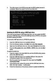
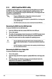
... corrupted during the updating process. Turn on the system. 3. Starting BIOS recovery... Recovering the BIOS from a floppy disk To recover the BIOS from the USB flash disk: 1. 5.1.3 ASUS CrashFree BIOS 3 utility The ASUS CrashFree BIOS 3 is an auto recovery tool that contains BIOS file to the USB port. 2. Recovering the BIOS from the USB flash disk To recover the...
... corrupted during the updating process. Turn on the system. 3. Starting BIOS recovery... Recovering the BIOS from a floppy disk To recover the BIOS from the USB flash disk: 1. 5.1.3 ASUS CrashFree BIOS 3 utility The ASUS CrashFree BIOS 3 is an auto recovery tool that contains BIOS file to the USB port. 2. Recovering the BIOS from the USB flash disk To recover the...
User Guide
Page 69
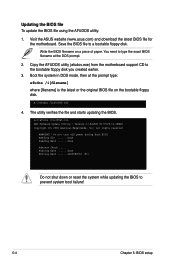
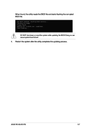
Start flashing... Doing so can cause system boot failure! 4. Starting BIOS recovery... Completed. Restart the system after the utility completes the updating process. Floppy found , the utility reads the BIOS file and starts flashing the corrupted BIOS file. DO NOT shut down or reset the system while updating the BIOS! When found ! Reading file "rs100e5.rom". ASUS RS100-E5-PI2 5-7 Checking for floppy... Bad BIOS checksum.
Start flashing... Doing so can cause system boot failure! 4. Starting BIOS recovery... Completed. Restart the system after the utility completes the updating process. Floppy found , the utility reads the BIOS file and starts flashing the corrupted BIOS file. DO NOT shut down or reset the system while updating the BIOS! When found ! Reading file "rs100e5.rom". ASUS RS100-E5-PI2 5-7 Checking for floppy... Bad BIOS checksum.
User Guide
Page 70
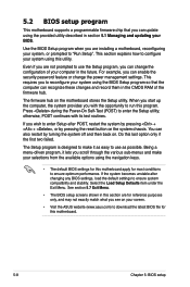
...BIOS setup screens shown in this section are installing a motherboard, reconfiguring your screen. • Visit the ASUS website (www.asus....com) to reconfigure your selections from the available options using this utility. This requires you to download the latest BIOS...BIOS Setup program when you are for most conditions to make your system using the BIOS...BIOS settings for this motherboard. 5-8 Chapter 5: BIOS setup Do this program. This section explains how to enter Setup after changing any BIOS... Menu. 5.2 BIOS setup program This motherboard supports a programmable firmware ...
...BIOS setup screens shown in this section are installing a motherboard, reconfiguring your screen. • Visit the ASUS website (www.asus....com) to reconfigure your selections from the available options using this utility. This requires you to download the latest BIOS...BIOS Setup program when you are for most conditions to make your system using the BIOS...BIOS settings for this motherboard. 5-8 Chapter 5: BIOS setup Do this program. This section explains how to enter Setup after changing any BIOS... Menu. 5.2 BIOS setup program This motherboard supports a programmable firmware ...
User Guide
Page 71
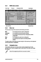
...differ from one screen to select items in the menu and change the settings. 5.2.1 BIOS menu screen Menu items Menu bar Configuration fields General help BIOS SETUP UTILITY Main Advanced Power Boot Exit System Time System Date Legacy Diskette A Primary ...TS] : [Hitachi HDS721616P] : [Not Detected] : [Not Detected] : [Hitachi HDS721616P] Use [ENTER]. [TAB], or [SHIFT-TAB] to configure system time. ASUS RS100-E5-PI2 5-9 Change Option F1 General Help F10 Save and Exit ESC Exit v02.58 (C)Copyright 1985-2004, American Megatrends, Inc. Use [+] or [-] to select a field...
...differ from one screen to select items in the menu and change the settings. 5.2.1 BIOS menu screen Menu items Menu bar Configuration fields General help BIOS SETUP UTILITY Main Advanced Power Boot Exit System Time System Date Legacy Diskette A Primary ...TS] : [Hitachi HDS721616P] : [Not Detected] : [Not Detected] : [Hitachi HDS721616P] Use [ENTER]. [TAB], or [SHIFT-TAB] to configure system time. ASUS RS100-E5-PI2 5-9 Change Option F1 General Help F10 Save and Exit ESC Exit v02.58 (C)Copyright 1985-2004, American Megatrends, Inc. Use [+] or [-] to select a field...
User Guide
Page 72
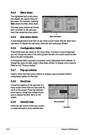
Refer to "4.2.7 Pop-up window." 5.2.7 Pop-up window Select a menu item then press to display a pop-up window Scroll bar 5-10 Chapter 5: BIOS setup To display the sub-menu, select the item and press . 5.2.6 Configuration fields These fields show the values for that menu. Use [+] or [-] to display a ...
Refer to "4.2.7 Pop-up window." 5.2.7 Pop-up window Select a menu item then press to display a pop-up window Scroll bar 5-10 Chapter 5: BIOS setup To display the sub-menu, select the item and press . 5.2.6 Configuration fields These fields show the values for that menu. Use [+] or [-] to display a ...
User Guide
Page 73
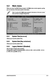
... options: [Disabled] [360K, 5.25 in.] [1.2M , 5.25 in.] [720K , 3.5 in.] [1.44M, 3.5 in.] [2.88M, 3.5 in.] ASUS RS100-E5-PI2 5-11 BIOS SETUP UTILITY Main Advanced Power Boot Exit System Time System Date Legacy Diskette A [11:10:19] [Mon 01/28/2008] [Disabled] Use [ENTER]. ...Allows you to set the system date. 5.3.3 Legacy Diskette A [Disabled] Sets the type of the basic system information. 5.3 Main menu When you enter the BIOS Setup program, the Main menu screen appears, giving you to select a field. Primary IDE Master Primary IDE Slave SATA 1 SATA 2 SATA 3 SATA 4 ...
... options: [Disabled] [360K, 5.25 in.] [1.2M , 5.25 in.] [720K , 3.5 in.] [1.44M, 3.5 in.] [2.88M, 3.5 in.] ASUS RS100-E5-PI2 5-11 BIOS SETUP UTILITY Main Advanced Power Boot Exit System Time System Date Legacy Diskette A [11:10:19] [Mon 01/28/2008] [Disabled] Use [ENTER]. ...Allows you to set the system date. 5.3.3 Legacy Diskette A [Disabled] Sets the type of the basic system information. 5.3 Main menu When you enter the BIOS Setup program, the Main menu screen appears, giving you to select a field. Primary IDE Master Primary IDE Slave SATA 1 SATA 2 SATA 3 SATA 4 ...


