
User Manual
Page 12
... and provide a satisfactory solution to model. 1.1 System package contents Check your system package for the following items. Model Name RS100-E10-PI2 Chassis ASUS R09 1U Rackmount Chassis Motherboard ASUS P11C-M/4L Server Board Component 1 x 250W Single Power Supply or 1 x 350W Single Power Supply* 2 x SATA Cables 1 x PCI Express x16 Riser Card 1 x Front I/O Board 3 x System Fans (40mm...
... and provide a satisfactory solution to model. 1.1 System package contents Check your system package for the following items. Model Name RS100-E10-PI2 Chassis ASUS R09 1U Rackmount Chassis Motherboard ASUS P11C-M/4L Server Board Component 1 x 250W Single Power Supply or 1 x 350W Single Power Supply* 2 x SATA Cables 1 x PCI Express x16 Riser Card 1 x Front I/O Board 3 x System Fans (40mm...
User Manual
Page 13
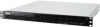
1.3 System specifications The ASUS RS100-E10-PI2 is for the purpose of easy debugging only. 2 x USB 3.1 Gen 2 ports 2 x USB 3.1 Gen 1 ports Rear I /O 1 x VGA port* * The full system supports a total of 1 VGA output, the front VGA is a 1U barebone server system featuring the ASUS P11C-M/4L server board. With ODD: 2 x 3.5" Internal HDD Bays (Optional 1 x 3.5" HDD + 2 ... 4 (2 Channels) Memory Capacity Memory Type Maximum up to 128GB (UDIMM) DDR4 2666/2400 ECC/non-ECC UDIMM * Refer to ASUS server AVL for ASMB9-iKVM) (Optional) (continued on the next page) ASUS RS100-E10-PI2 1-3
1.3 System specifications The ASUS RS100-E10-PI2 is for the purpose of easy debugging only. 2 x USB 3.1 Gen 2 ports 2 x USB 3.1 Gen 1 ports Rear I /O 1 x VGA port* * The full system supports a total of 1 VGA output, the front VGA is a 1U barebone server system featuring the ASUS P11C-M/4L server board. With ODD: 2 x 3.5" Internal HDD Bays (Optional 1 x 3.5" HDD + 2 ... 4 (2 Channels) Memory Capacity Memory Type Maximum up to 128GB (UDIMM) DDR4 2666/2400 ECC/non-ECC UDIMM * Refer to ASUS server AVL for ASMB9-iKVM) (Optional) (continued on the next page) ASUS RS100-E10-PI2 1-3
User Manual
Page 15
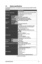
...Code LED Power button Location LED Message LED USB 3.1 Gen 2 ports VGA port *This port is for the LED descriptions. ASUS RS100-E10-PI2 1-5 1.4 Front panel features This barebone server has a simple yet stylish front panel with openings for the rear panel connectors on the motherboard are located on the front panel...system component. 1.5 Rear panel features The rear panel has the AC power socket and access to section 1.7.1 Front panel LEDs for an ASUS ASMB9-iKVM controller card only. The power and reset buttons, LED indicators, optical drive, and two USB ports are also found in ...
...Code LED Power button Location LED Message LED USB 3.1 Gen 2 ports VGA port *This port is for the LED descriptions. ASUS RS100-E10-PI2 1-5 1.4 Front panel features This barebone server has a simple yet stylish front panel with openings for the rear panel connectors on the motherboard are located on the front panel...system component. 1.5 Rear panel features The rear panel has the AC power socket and access to section 1.7.1 Front panel LEDs for an ASUS ASMB9-iKVM controller card only. The power and reset buttons, LED indicators, optical drive, and two USB ports are also found in ...
User Manual
Page 31
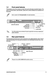
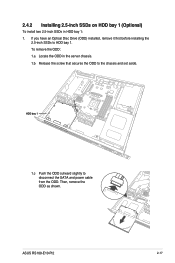
To remove the ODD: 1.a Locate the ODD in the server chassis. 1.b Release the screw that secures the ODD to disconnect the SATA and power cable from the ODD. HDD bay 1 1.c Push the ODD outward slightly to the chassis and set aside. ASUS RS100-E10-PI2 2-13 If you have an Optical Disc Drive (ODD) installed, remove... drive to the HDD bay 1 To install a 3.5-inch Serial ATA HDD to HDD bay 1. inch Sertial ATA HDD to HDD bay 1: 1. 2.4 Hard disk drives The server chassis has two HDD bays for installing HDDs to the system.
To remove the ODD: 1.a Locate the ODD in the server chassis. 1.b Release the screw that secures the ODD to disconnect the SATA and power cable from the ODD. HDD bay 1 1.c Push the ODD outward slightly to the chassis and set aside. ASUS RS100-E10-PI2 2-13 If you have an Optical Disc Drive (ODD) installed, remove... drive to the HDD bay 1 To install a 3.5-inch Serial ATA HDD to HDD bay 1. inch Sertial ATA HDD to HDD bay 1: 1. 2.4 Hard disk drives The server chassis has two HDD bays for installing HDDs to the system.
User Manual
Page 35
HDD bay 1 1.c Push the ODD outward slightly to the chassis and set aside. ASUS RS100-E10-PI2 2-17 2.4.2 Installing 2.5-inch SSDs on HDD bay 1 (Optional) To install two 2.5-inch SSDs in the server chassis. 1.b Release the screw that secures the ODD to disconnect the SATA and power cable from the ODD. To remove the ODD: 1.a Locate the ODD in HDD bay 1: 1. If you have an Optical Disc Drive (ODD) installed, remove it first before installing the 2.5-inch SSDs to HDD bay 1. Then, remove the ODD as shown.
HDD bay 1 1.c Push the ODD outward slightly to the chassis and set aside. ASUS RS100-E10-PI2 2-17 2.4.2 Installing 2.5-inch SSDs on HDD bay 1 (Optional) To install two 2.5-inch SSDs in the server chassis. 1.b Release the screw that secures the ODD to disconnect the SATA and power cable from the ODD. To remove the ODD: 1.a Locate the ODD in HDD bay 1: 1. If you have an Optical Disc Drive (ODD) installed, remove it first before installing the 2.5-inch SSDs to HDD bay 1. Then, remove the ODD as shown.
User Manual
Page 51
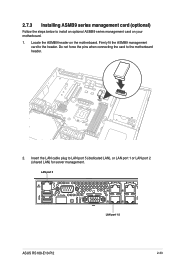
Insert the LAN cable plug to the motherboard header. 4 2. Locate the ASMB9 header on your motherboard. 1. Do not force the pins when connecting the card to LAN port 5 (dedicated LAN), or LAN port 1 or LAN port 2 (shared LAN) for server management. Firmly fit the ASMB9 management card to the header. LAN port 5 Q-Code 2 4 1 3 LAN port 1-2 ASUS RS100-E10-PI2 2-33 2.7.3 Installing ASMB9 series management card (optional) Follow the steps below to install an optional ASMB9 series management card on the motherboard.
Insert the LAN cable plug to the motherboard header. 4 2. Locate the ASMB9 header on your motherboard. 1. Do not force the pins when connecting the card to LAN port 5 (dedicated LAN), or LAN port 1 or LAN port 2 (shared LAN) for server management. Firmly fit the ASMB9 management card to the header. LAN port 5 Q-Code 2 4 1 3 LAN port 1-2 ASUS RS100-E10-PI2 2-33 2.7.3 Installing ASMB9 series management card (optional) Follow the steps below to install an optional ASMB9 series management card on the motherboard.
User Manual
Page 55
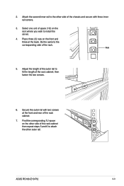
ASUS RS100-E10-PI2 3-3 Select one unit of space (1U) on the rack where you wish to the corresponding side of the rack. Place three (3) nuts on the other ... 5 and 6 to attach the other side of the rack cabinet. 7. Secure the outer rail with three inner rail screws. 3. Do the same to install the server. 4. Find the corresponding 1U space on the front and three at the front and rear of the chassis and secure with two screws at the...
ASUS RS100-E10-PI2 3-3 Select one unit of space (1U) on the rack where you wish to the corresponding side of the rack. Place three (3) nuts on the other ... 5 and 6 to attach the other side of the rack cabinet. 7. Secure the outer rail with three inner rail screws. 3. Do the same to install the server. 4. Find the corresponding 1U space on the front and three at the front and rear of the chassis and secure with two screws at the...
User Manual
Page 57
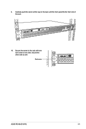
Rack screw 4 3 2 1 ASUS RS100-E10-PI2 3-5 Carefully push the server all the way to the rack with one rack screw at one side. 9. Secure the server to the back until the front panel fits the front end of the rack. 4 3 2 1 10. Secure the other side as well.
Rack screw 4 3 2 1 ASUS RS100-E10-PI2 3-5 Carefully push the server all the way to the rack with one rack screw at one side. 9. Secure the server to the back until the front panel fits the front end of the rack. 4 3 2 1 10. Secure the other side as well.

User Manual
Page 93
... options for special functions Event Logs For changing the event log settings Server Mgmt For changing the server mgmt settings Save & Exit For selecting the save & exit options To select an item on the menu bar, press the right or left arrow key on the keyboard until the desired item is highlighted. ASUS RS100-E10-PI2 5-7
... options for special functions Event Logs For changing the event log settings Server Mgmt For changing the server mgmt settings Save & Exit For selecting the save & exit options To select an item on the menu bar, press the right or left arrow key on the keyboard until the desired item is highlighted. ASUS RS100-E10-PI2 5-7
User Manual
Page 107
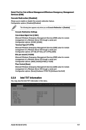
... [VT-UTF8] [ANSI] Bits per second [115200] Microsoft Windows Emergency Management Services (EMS) allow for remote management of a Windows Server OS through a serial port. Configuration options: [None] [Hardware RTS/CTS] [Software Xon/Xoff] 5.5.9 Intel TXT Information You may view... Out-of-Band Mgmt Port [COM1] Microsoft Windows Emergency Management Services (EMS) allow for remote management of a Windows Server OS through a serial port. ASUS RS100-E10-PI2 5-21 Configuration options: [Disabled] [Enabled] The following item appears only when you to [Enabled]. Configuration options: ...
... [VT-UTF8] [ANSI] Bits per second [115200] Microsoft Windows Emergency Management Services (EMS) allow for remote management of a Windows Server OS through a serial port. Configuration options: [None] [Hardware RTS/CTS] [Software Xon/Xoff] 5.5.9 Intel TXT Information You may view... Out-of-Band Mgmt Port [COM1] Microsoft Windows Emergency Management Services (EMS) allow for remote management of a Windows Server OS through a serial port. ASUS RS100-E10-PI2 5-21 Configuration options: [Disabled] [Enabled] The following item appears only when you to [Enabled]. Configuration options: ...
User Manual
Page 147
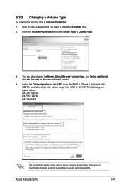
... change the volume type in Volume Properties: 1. The following are typical values: RAID 0: 128KB RAID 10: 64KB RAID 5: 64KB We recommend a lower stripe size for server systems, and a higher stripe size for multimedia computer systems used mainly for RAID 0, 10 and 5 only) and click OK. From the Volume Properties field, select..., Select the new volume type, and Select additional disks to include in Volumes field. 2. The available stripe size values range from 4 KB to 128 KB. ASUS RS100-E10-PI2 6-15
... change the volume type in Volume Properties: 1. The following are typical values: RAID 0: 128KB RAID 10: 64KB RAID 5: 64KB We recommend a lower stripe size for server systems, and a higher stripe size for multimedia computer systems used mainly for RAID 0, 10 and 5 only) and click OK. From the Volume Properties field, select..., Select the new volume type, and Select additional disks to include in Volumes field. 2. The available stripe size values range from 4 KB to 128 KB. ASUS RS100-E10-PI2 6-15

User Manual
Page 155
ASUS RS100-E10-PI2 7-5 The screenshots are provided for the latest updates on software and utilities. • The support DVD is supported on the motherboard and chipset. By default, the Drivers tab is displayed. If Autorun is NOT enabled in your computer. Onscreen display and content vary depending on Windows® Server 2016. 7.3 Running the Support...
ASUS RS100-E10-PI2 7-5 The screenshots are provided for the latest updates on software and utilities. • The support DVD is supported on the motherboard and chipset. By default, the Drivers tab is displayed. If Autorun is NOT enabled in your computer. Onscreen display and content vary depending on Windows® Server 2016. 7.3 Running the Support...
