User Manual
Page 13
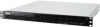
1.3 System specifications The ASUS RS100-E10-PI2 is for the purpose of easy debugging only. 2 x USB 3.1 Gen 2 ports 2 x USB 3.1 Gen 1 ports Rear I /O 1 x VGA port* * The full system supports a total of 1 VGA output, the front VGA is a 1U barebone server system featuring the ASUS P11C-M/4L server board. With ODD: 2 x 3.5" Internal HDD Bays (Optional 1 x 3.5" HDD ... 4 (2 Channels) Memory Capacity Memory Type Maximum up to 128GB (UDIMM) DDR4 2666/2400 ECC/non-ECC UDIMM * Refer to ASUS server AVL for ASMB9-iKVM) (Optional) (continued on the next page) ASUS RS100-E10-PI2 1-3
1.3 System specifications The ASUS RS100-E10-PI2 is for the purpose of easy debugging only. 2 x USB 3.1 Gen 2 ports 2 x USB 3.1 Gen 1 ports Rear I /O 1 x VGA port* * The full system supports a total of 1 VGA output, the front VGA is a 1U barebone server system featuring the ASUS P11C-M/4L server board. With ODD: 2 x 3.5" Internal HDD Bays (Optional 1 x 3.5" HDD ... 4 (2 Channels) Memory Capacity Memory Type Maximum up to 128GB (UDIMM) DDR4 2666/2400 ECC/non-ECC UDIMM * Refer to ASUS server AVL for ASMB9-iKVM) (Optional) (continued on the next page) ASUS RS100-E10-PI2 1-3
User Manual
Page 15
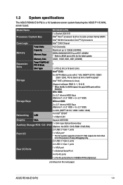
... port 1-2 Q-Code 2 4 1 3 USB 3.1 Gen 1 ports Q-Code LED Power button Location LED Message LED USB 3.1 Gen 2 ports VGA port *This port is for the LED descriptions. ASUS RS100-E10-PI2 1-5 The power and reset buttons, LED indicators, optical drive, and two USB ports are located on the motherboard are also found in the rear panel... or replacing any system component. 1.5 Rear panel features The rear panel has the AC power socket and access to section 1.7.1 Front panel LEDs for an ASUS ASMB9-iKVM controller card only. Refer to any added expansion cards.
... port 1-2 Q-Code 2 4 1 3 USB 3.1 Gen 1 ports Q-Code LED Power button Location LED Message LED USB 3.1 Gen 2 ports VGA port *This port is for the LED descriptions. ASUS RS100-E10-PI2 1-5 The power and reset buttons, LED indicators, optical drive, and two USB ports are located on the motherboard are also found in the rear panel... or replacing any system component. 1.5 Rear panel features The rear panel has the AC power socket and access to section 1.7.1 Front panel LEDs for an ASUS ASMB9-iKVM controller card only. Refer to any added expansion cards.

User Manual
Page 17
... Location LED LAN LEDs Display status Description ON System power ON OFF No activity Blinking Read/write data into the HDD OFF System is present ASUS RS100-E10-PI2 1-7 no incoming event ON A hardware monitor event is indicated OFF Normal status ON OFF Blinking ON Location switch is pressed (Press the location switch again...
... Location LED LAN LEDs Display status Description ON System power ON OFF No activity Blinking Read/write data into the HDD OFF System is present ASUS RS100-E10-PI2 1-7 no incoming event ON A hardware monitor event is indicated OFF Normal status ON OFF Blinking ON Location switch is pressed (Press the location switch again...

User Manual
Page 21
Side tabs ASUS RS100-E10-PI2 2-3 2.1.2 Reinstalling the chassis cover To reinstall the chassis cover: 1. Position the cover on top of the chassis with the hooks aligned to the side tabs of the chassis.
Side tabs ASUS RS100-E10-PI2 2-3 2.1.2 Reinstalling the chassis cover To reinstall the chassis cover: 1. Position the cover on top of the chassis with the hooks aligned to the side tabs of the chassis.

User Manual
Page 23
ASUS RS100-E10-PI2 2-5 Locate the CPU socket on your right. The product warranty does not cover damage to the socket contacts resulting from incorrect CPU installation/removal, or ...
ASUS RS100-E10-PI2 2-5 Locate the CPU socket on your right. The product warranty does not cover damage to the socket contacts resulting from incorrect CPU installation/removal, or ...

User Manual
Page 25
Load lever 6. ASUS RS100-E10-PI2 Retention lock Load lever Retention tab 2-7 Apply some Thermal Interface Material to the exposed area of the load plate slides under the retention tab to ...
Load lever 6. ASUS RS100-E10-PI2 Retention lock Load lever Retention tab 2-7 Apply some Thermal Interface Material to the exposed area of the load plate slides under the retention tab to ...
User Manual
Page 27
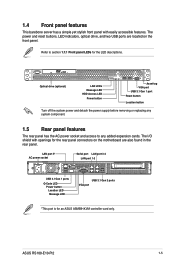
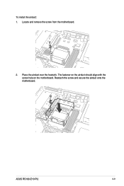
The fastener on the airduct should align with the screw hole on the motherboard. ASUS RS100-E10-PI2 2-9 To install the airduct: 1. Locate and remove the screw from the motherboard. 2. Reattach the screw and secure the airduct onto the motherboard. Place the airduct over the heatsink.
The fastener on the airduct should align with the screw hole on the motherboard. ASUS RS100-E10-PI2 2-9 To install the airduct: 1. Locate and remove the screw from the motherboard. 2. Reattach the screw and secure the airduct onto the motherboard. Place the airduct over the heatsink.

User Manual
Page 29
... vertically into place and the DIMM cannot be pushed in the wrong direction to both ends of the DIMM. Hold the DIMM on the socket. ASUS RS100-E10-PI2 2-11 Unlock a DIMM socket by pressing the retaining clip outward. Apply force to avoid damaging the DIMM. 3. Locked Retaining Clip Always insert the DIMM into...
... vertically into place and the DIMM cannot be pushed in the wrong direction to both ends of the DIMM. Hold the DIMM on the socket. ASUS RS100-E10-PI2 2-11 Unlock a DIMM socket by pressing the retaining clip outward. Apply force to avoid damaging the DIMM. 3. Locked Retaining Clip Always insert the DIMM into...
User Manual
Page 31
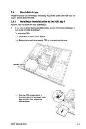
... chassis and set aside. To remove the ODD: 1.a Locate the ODD in the server chassis. 1.b Release the screw that secures the ODD to HDD bay 1. ASUS RS100-E10-PI2 2-13 If you have an Optical Disc Drive (ODD) installed, remove it first before installing a 3.5- HDD bay 1 1.c Push the ODD outward slightly to disconnect the...
... chassis and set aside. To remove the ODD: 1.a Locate the ODD in the server chassis. 1.b Release the screw that secures the ODD to HDD bay 1. ASUS RS100-E10-PI2 2-13 If you have an Optical Disc Drive (ODD) installed, remove it first before installing a 3.5- HDD bay 1 1.c Push the ODD outward slightly to disconnect the...
User Manual
Page 33
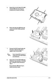
Connect the SATA signal cable and the power cable from the power supply to the motherboard. 8. 5. Ensure that the HDD drive tray is seated securely in step 2. Use an L-type SATA connector to connect the 3.5-inch SATA HDD to the 3.5-inch HDD. Secure the 3.5-inch SATA HDD and HDD drive tray assembly to the HDD bay 1 using the bundled set of screws (as shown. 7. Place and orient the HDD drive tray and 3.5-inch SATA HDD assembly as shown). 6. ASUS RS100-E10-PI2 2-15 Secure the 3.5-inch Serial ATA HDD into the HDD drive tray using the screws removed in place.
Connect the SATA signal cable and the power cable from the power supply to the motherboard. 8. 5. Ensure that the HDD drive tray is seated securely in step 2. Use an L-type SATA connector to connect the 3.5-inch SATA HDD to the 3.5-inch HDD. Secure the 3.5-inch SATA HDD and HDD drive tray assembly to the HDD bay 1 using the bundled set of screws (as shown. 7. Place and orient the HDD drive tray and 3.5-inch SATA HDD assembly as shown). 6. ASUS RS100-E10-PI2 2-15 Secure the 3.5-inch Serial ATA HDD into the HDD drive tray using the screws removed in place.
User Manual
Page 35
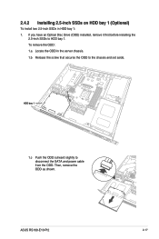
Then, remove the ODD as shown. 2.4.2 Installing 2.5-inch SSDs on HDD bay 1 (Optional) To install two 2.5-inch SSDs in the server chassis. 1.b Release the screw that secures the ODD to the chassis and set aside. HDD bay 1 1.c Push the ODD outward slightly to HDD bay 1. ASUS RS100-E10-PI2 2-17 If you have an Optical Disc Drive (ODD) installed, remove it first before installing the 2.5-inch SSDs to disconnect the SATA and power cable from the ODD. To remove the ODD: 1.a Locate the ODD in HDD bay 1: 1.
Then, remove the ODD as shown. 2.4.2 Installing 2.5-inch SSDs on HDD bay 1 (Optional) To install two 2.5-inch SSDs in the server chassis. 1.b Release the screw that secures the ODD to the chassis and set aside. HDD bay 1 1.c Push the ODD outward slightly to HDD bay 1. ASUS RS100-E10-PI2 2-17 If you have an Optical Disc Drive (ODD) installed, remove it first before installing the 2.5-inch SSDs to disconnect the SATA and power cable from the ODD. To remove the ODD: 1.a Locate the ODD in HDD bay 1: 1.
User Manual
Page 37
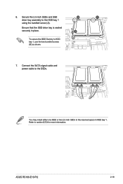
Secure the 2.5-inch SSDs and SSD drive tray assembly to the SSDs. Connect the SATA signal cable and power cable to the HDD bay 1 using the bundled screw (A). Ensure that the SSD drive tray is seated securely in HDD bay 1. ASUS RS100-E10-PI2 2-19 Refer to HDD bay 1, use the two bundled screws (B) as shown. 7. 6. To secure the ODD Dummy to section 2.7.3 for more information. You may install either one ODD or two 2.5-inch SSDs to the reserved space in place.
Secure the 2.5-inch SSDs and SSD drive tray assembly to the SSDs. Connect the SATA signal cable and power cable to the HDD bay 1 using the bundled screw (A). Ensure that the SSD drive tray is seated securely in HDD bay 1. ASUS RS100-E10-PI2 2-19 Refer to HDD bay 1, use the two bundled screws (B) as shown. 7. 6. To secure the ODD Dummy to section 2.7.3 for more information. You may install either one ODD or two 2.5-inch SSDs to the reserved space in place.

User Manual
Page 39
Secure the 3.5-inch Serial ATA HDD into the HDD drive tray. Connect the SATA signal cable and the power cable from the power supply to the motherboard. Use an L-type SATA connector to connect the 3.5-inch SATA HDD to the 3.5-inch HDD. Insert a 3.5-inch Serial ATA HDD into the HDD drive tray using the bundled set of screws (as shown). 6. Ensure that the 3.5-inch SATA HDD is seated securely in place. 5. SATA power cable SATA signal cable ASUS RS100-E10-PI2 2-21 4.
Secure the 3.5-inch Serial ATA HDD into the HDD drive tray. Connect the SATA signal cable and the power cable from the power supply to the motherboard. Use an L-type SATA connector to connect the 3.5-inch SATA HDD to the 3.5-inch HDD. Insert a 3.5-inch Serial ATA HDD into the HDD drive tray using the bundled set of screws (as shown). 6. Ensure that the 3.5-inch SATA HDD is seated securely in place. 5. SATA power cable SATA signal cable ASUS RS100-E10-PI2 2-21 4.

User Manual
Page 41
Locate the 3.5-inch Serial ATA HDD and the HDD drive tray assembly in HDD bay 2: 1. Release the four screws that secure the HDD drive tray and 3.5-inch SATA HDD assembly to HDD bay 2 and set aside. Remove the HDD drive tray and set aside. 4. 2.4.4 Installing 2.5-inch SSDs on HDD bay 2 (Optional) To replace an installed 3.5-inch Serial ATA HDD with two 2.5-inch SSDs in the chassis. 2. Disconnect the SATA cable and power cable from the 3.5-inch SATA HDD. 3. ASUS RS100-E10-PI2 2-23
Locate the 3.5-inch Serial ATA HDD and the HDD drive tray assembly in HDD bay 2: 1. Release the four screws that secure the HDD drive tray and 3.5-inch SATA HDD assembly to HDD bay 2 and set aside. Remove the HDD drive tray and set aside. 4. 2.4.4 Installing 2.5-inch SSDs on HDD bay 2 (Optional) To replace an installed 3.5-inch Serial ATA HDD with two 2.5-inch SSDs in the chassis. 2. Disconnect the SATA cable and power cable from the 3.5-inch SATA HDD. 3. ASUS RS100-E10-PI2 2-23

User Manual
Page 43
Connect the 4-pin power connector of the power cable to the SATA connector on accessory. Connect the other end of -place. Use the SATA power cable that no cables or connectors are out-of the SATA signal cable to the 4-pin power connector from the power supply. SSD 2 SSD 1 11. ASUS RS100-E10-PI2 2-25 10. Connect the SATA signal cable and power cable to the 2.5-inch SSD as an add-on the motherboard. 12. Ensure that comes with the SSD drive tray as shown.
Connect the 4-pin power connector of the power cable to the SATA connector on accessory. Connect the other end of -place. Use the SATA power cable that no cables or connectors are out-of the SATA signal cable to the 4-pin power connector from the power supply. SSD 2 SSD 1 11. ASUS RS100-E10-PI2 2-25 10. Connect the SATA signal cable and power cable to the 2.5-inch SSD as an add-on the motherboard. 12. Ensure that comes with the SSD drive tray as shown.

User Manual
Page 45
Install the expansion card to the riser card (C). 6. Install the expansion card and the riser card assembly into the PCIE connector on the motherboard (D). ASUS RS100-E10-PI2 2-27 Secure the bracket using the screw removed in place. 7. Enusre that the golden connectors of the riser card are seated firmly in step 2. 4. Install the expansion card to the bracket (A) and secure the expansion card with the screw removed in step 3 (B). 5.
Install the expansion card to the riser card (C). 6. Install the expansion card and the riser card assembly into the PCIE connector on the motherboard (D). ASUS RS100-E10-PI2 2-27 Secure the bracket using the screw removed in place. 7. Enusre that the golden connectors of the riser card are seated firmly in step 2. 4. Install the expansion card to the bracket (A) and secure the expansion card with the screw removed in step 3 (B). 5.

User Manual
Page 47
Secure the M.2 card to the motherboard using the screw removed in step 2. Remove the screw from the motherboard. 3. ASUS RS100-E10-PI2 2-29 Align and insert the M.2 card into the M.2 connector on the motherboard. 2. Locate the M.2 (NGFF) card connector on the motherboard. 5. Prepare the M.2 card. 4. 2.5.3 Installing M.2 (NGFF) cards To install an M.2 (NGFF) card: 1.
Secure the M.2 card to the motherboard using the screw removed in step 2. Remove the screw from the motherboard. 3. ASUS RS100-E10-PI2 2-29 Align and insert the M.2 card into the M.2 connector on the motherboard. 2. Locate the M.2 (NGFF) card connector on the motherboard. 5. Prepare the M.2 card. 4. 2.5.3 Installing M.2 (NGFF) cards To install an M.2 (NGFF) card: 1.

User Manual
Page 49
...-iKVM (optional) Ensure that the system is turned off before removing any components. 2.7.1 System fans To install the system fans: 1. ASUS RS100-E10-PI2 2-31 System fans 2. 2.7 Removable/optional components You may need to remove previously installed system components when installing or removing system devices or you may need ...
...-iKVM (optional) Ensure that the system is turned off before removing any components. 2.7.1 System fans To install the system fans: 1. ASUS RS100-E10-PI2 2-31 System fans 2. 2.7 Removable/optional components You may need to remove previously installed system components when installing or removing system devices or you may need ...
User Manual
Page 51
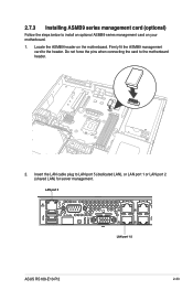
LAN port 5 Q-Code 2 4 1 3 LAN port 1-2 ASUS RS100-E10-PI2 2-33 2.7.3 Installing ASMB9 series management card (optional) Follow the steps below to the header. Firmly fit the ASMB9 management card to install an optional ASMB9 series management card on the motherboard. Locate the ASMB9 header on your motherboard. 1. Do not force the pins when connecting the card to LAN port 5 (dedicated LAN), or LAN port 1 or LAN port 2 (shared LAN) for server management. Insert the LAN cable plug to the motherboard header. 4 2.
LAN port 5 Q-Code 2 4 1 3 LAN port 1-2 ASUS RS100-E10-PI2 2-33 2.7.3 Installing ASMB9 series management card (optional) Follow the steps below to the header. Firmly fit the ASMB9 management card to install an optional ASMB9 series management card on the motherboard. Locate the ASMB9 header on your motherboard. 1. Do not force the pins when connecting the card to LAN port 5 (dedicated LAN), or LAN port 1 or LAN port 2 (shared LAN) for server management. Insert the LAN cable plug to the motherboard header. 4 2.
User Manual
Page 55
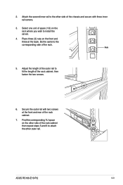
... unit of the rack cabinet. 7. Attach the second inner rail to the corresponding side of the chassis and secure with two screws at the back. ASUS RS100-E10-PI2 3-3 Do the same to the other side of the rack cabinet, then fasten the two screws. 6.
... unit of the rack cabinet. 7. Attach the second inner rail to the corresponding side of the chassis and secure with two screws at the back. ASUS RS100-E10-PI2 3-3 Do the same to the other side of the rack cabinet, then fasten the two screws. 6.


