
RAMPAGE IV BLACK EDITION User's Manual
Page 1
Motherboard RAMPAGE IV BLACK EDITION
Motherboard RAMPAGE IV BLACK EDITION
RAMPAGE IV BLACK EDITION User's Manual
Page 3
......vi About this guide...vii RAMPAGE IV BLACK EDITION specifications summary ix OC Panel specifications summary xiii Package contents...xiv Installation tools and components xv Chapter 1: Product Introduction 1.1 Special features 1-1 1.1.1 Product highlights 1-1 1.1.2 ROG Unique Gaming Features 1-2 1.1.3 ROG exclusive features 1-3 1.1.4 ASUS special features 1-5 1.1.5 ROG rich-bundled software 1-6 1.2 Motherboard overview 1-7 1.2.1 Before you proceed 1-7 1.2.2 Motherboard layout 1-8 1.2.3 Central Processing Unit (CPU...
......vi About this guide...vii RAMPAGE IV BLACK EDITION specifications summary ix OC Panel specifications summary xiii Package contents...xiv Installation tools and components xv Chapter 1: Product Introduction 1.1 Special features 1-1 1.1.1 Product highlights 1-1 1.1.2 ROG Unique Gaming Features 1-2 1.1.3 ROG exclusive features 1-3 1.1.4 ASUS special features 1-5 1.1.5 ROG rich-bundled software 1-6 1.2 Motherboard overview 1-7 1.2.1 Before you proceed 1-7 1.2.2 Motherboard layout 1-8 1.2.3 Central Processing Unit (CPU...
RAMPAGE IV BLACK EDITION User's Manual
Page 9
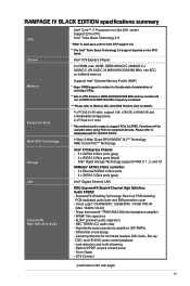
RAMPAGE IV BLACK EDITION specifications summary CPU Chipset Memory Expansion Slots Multi-GPU Technology Storage LAN SupremeFX High Definition Audio Intel® Core™ i7 Processors for LGA 2011 socket Support 22nm CPU Intel® Turbo Boost Technology 2.0 * Refer to www.asus.com for details. 4 x PCIe3.0 x16 ... - Please refer to support PCIe 3.0 SPEC. x16/x8/x16 and x16/x8/x8/x8 configurations 2 x PCIe2.0 x1 slots * This motherboard is subject to the physical characteristics of individual CPUs. ** Due to Memory QVL (Qualified Vendors List) for Intel CPU support list. ** The...
RAMPAGE IV BLACK EDITION specifications summary CPU Chipset Memory Expansion Slots Multi-GPU Technology Storage LAN SupremeFX High Definition Audio Intel® Core™ i7 Processors for LGA 2011 socket Support 22nm CPU Intel® Turbo Boost Technology 2.0 * Refer to www.asus.com for details. 4 x PCIe3.0 x16 ... - Please refer to support PCIe 3.0 SPEC. x16/x8/x16 and x16/x8/x8/x8 configurations 2 x PCIe2.0 x1 slots * This motherboard is subject to the physical characteristics of individual CPUs. ** Due to Memory QVL (Qualified Vendors List) for Intel CPU support list. ** The...
RAMPAGE IV BLACK EDITION User's Manual
Page 13
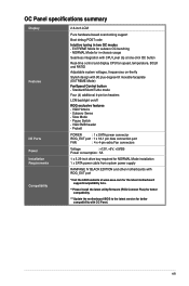
... Pure hardware-based overclocking support Boot debug POST code Intuitive tuning in -chassis usage Seamless integration with CPU Level Up at www.asus.com for the latest motherboard support/compatibility lists. **Please install the latest utility/firmware (ROG Connect Plus) for better compatibility. ***Update the... - VGA Hotwire - Slow Mode - VGA SMB header - Pause Switch - EXTREME Mode for NORMAL Mode installation 1 x SATA power cable from system power supply RAMPAGE IV BLACK EDITION and other motherboards with 90 plus-degree-tilt movable faceplate (EXTREME Mode) FanSpeed Control button -
... Pure hardware-based overclocking support Boot debug POST code Intuitive tuning in -chassis usage Seamless integration with CPU Level Up at www.asus.com for the latest motherboard support/compatibility lists. **Please install the latest utility/firmware (ROG Connect Plus) for better compatibility. ***Update the... - VGA Hotwire - Slow Mode - VGA SMB header - Pause Switch - EXTREME Mode for NORMAL Mode installation 1 x SATA power cable from system power supply RAMPAGE IV BLACK EDITION and other motherboards with 90 plus-degree-tilt movable faceplate (EXTREME Mode) FanSpeed Control button -
RAMPAGE IV BLACK EDITION User's Manual
Page 14
Package contents Check your motherboard package for the following items. Motherboard Cables Accessories Application DVD Documentation ROG RAMPAGE IV BLACK EDITION 1 x ROG Connect cable 2 x 2-in-1 SATA 3.0 Gb/s signal cables 3 x 2-in-1 SATA 6.0 Gb/s signal cables 1 x SLI® cable 1 x CrossFireTM cable 1 x I/O... x 2T2R dual-band Wi-Fi moving antennas 1 x ROG Magnet 1 x 2-in-1 ASUS Q-Connector Kit 1 x 12-in-1 ROG Cable label 1 x X-Socket pad 1 x 4-WAY SLI® bridge 1 x 3-WAY SLI® bridge ROG motherboard support DVD User's manual If any of the above items is damaged or missing, contact ...
Package contents Check your motherboard package for the following items. Motherboard Cables Accessories Application DVD Documentation ROG RAMPAGE IV BLACK EDITION 1 x ROG Connect cable 2 x 2-in-1 SATA 3.0 Gb/s signal cables 3 x 2-in-1 SATA 6.0 Gb/s signal cables 1 x SLI® cable 1 x CrossFireTM cable 1 x I/O... x 2T2R dual-band Wi-Fi moving antennas 1 x ROG Magnet 1 x 2-in-1 ASUS Q-Connector Kit 1 x 12-in-1 ROG Cable label 1 x X-Socket pad 1 x 4-WAY SLI® bridge 1 x 3-WAY SLI® bridge ROG motherboard support DVD User's manual If any of the above items is damaged or missing, contact ...
RAMPAGE IV BLACK EDITION User's Manual
Page 17
... X79 Express Chipset Intel® X79 Express Chipset is ready to www.asus.com for updated details. 3-Way/4-way/Quad-GPU SLI™ and CrossFireX™ Support This motherboard features the most powerful Intel® X79 platform that optimizes PCIe allocation in...performance. * This motherboard is a single chipset that features data transfer rates of DDR3 2800(O.C.)/ 2666(O.C.)/ 2400(O.C.)/ 2133(O.C.)/ 1866/ 1600/ 1333/ 1066 MHz to boost the system's performance, and to meet the higher bandwidth requirements of current bus systems. Chapter 1 ASUS RAMPAGE IV BLACK EDITION 1-1 Extra SATA ...
... X79 Express Chipset Intel® X79 Express Chipset is ready to www.asus.com for updated details. 3-Way/4-way/Quad-GPU SLI™ and CrossFireX™ Support This motherboard features the most powerful Intel® X79 platform that optimizes PCIe allocation in...performance. * This motherboard is a single chipset that features data transfer rates of DDR3 2800(O.C.)/ 2666(O.C.)/ 2400(O.C.)/ 2133(O.C.)/ 1866/ 1600/ 1333/ 1066 MHz to boost the system's performance, and to meet the higher bandwidth requirements of current bus systems. Chapter 1 ASUS RAMPAGE IV BLACK EDITION 1-1 Extra SATA ...
RAMPAGE IV BLACK EDITION User's Manual
Page 19
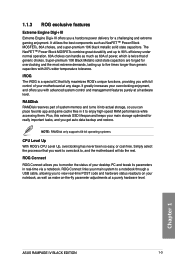
...select the processor that you can handle as much as 60A of power, which is a special IC that of generic chokes. Chapter 1 ASUS RAMPAGE IV BLACK EDITION 1-3 ROG Connect ROG Connect allows you a hardcore power delivery for a challenging and extreme gaming enjoyment. 1.1.3 ROG exclusive features Extreme Engine...durability and up to a notebook through a USB cable, allowing you get auto data backup and restore. ROG Connect links your motherboard at a purely hardware level. It greatly increases your overclocking enjoyment, and offers you with full control of your main system to...
...select the processor that you can handle as much as 60A of power, which is a special IC that of generic chokes. Chapter 1 ASUS RAMPAGE IV BLACK EDITION 1-3 ROG Connect ROG Connect allows you a hardcore power delivery for a challenging and extreme gaming enjoyment. 1.1.3 ROG exclusive features Extreme Engine...durability and up to a notebook through a USB cable, allowing you get auto data backup and restore. ROG Connect links your motherboard at a purely hardware level. It greatly increases your overclocking enjoyment, and offers you with full control of your main system to...
RAMPAGE IV BLACK EDITION User's Manual
Page 23
... object, such as the power supply case, to avoid damaging them due to static electricity. • Hold components by the edges to the motherboard, peripherals, or components. Chapter 1 ASUS RAMPAGE IV BLACK EDITION 1-7 Failure to do so may cause severe damage to avoid touching the ICs on them. • Whenever you uninstall any component, place it... or in the bag that the ATX power supply is switched off or the power cord is detached from the wall socket before touching any motherboard settings. • Unplug the power cord from the power supply.
... object, such as the power supply case, to avoid damaging them due to static electricity. • Hold components by the edges to the motherboard, peripherals, or components. Chapter 1 ASUS RAMPAGE IV BLACK EDITION 1-7 Failure to do so may cause severe damage to avoid touching the ICs on them. • Whenever you uninstall any component, place it... or in the bag that the ATX power supply is switched off or the power cord is detached from the wall socket before touching any motherboard settings. • Unplug the power cord from the power supply.
RAMPAGE IV BLACK EDITION User's Manual
Page 27
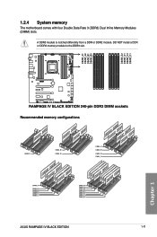
Recommended memory configurations Chapter 1 ASUS RAMPAGE IV BLACK EDITION 1-11 DO NOT install a DDR or DDR2 memory module to the DDR3 slot. A DDR3 module is notched differently from a DDR or DDR2 module. 1.2.4 System memory The motherboard comes with four Double Data Rate 3 (DDR3) Dual Inline Memory Modules (DIMM) slots.
Recommended memory configurations Chapter 1 ASUS RAMPAGE IV BLACK EDITION 1-11 DO NOT install a DDR or DDR2 memory module to the DDR3 slot. A DDR3 module is notched differently from a DDR or DDR2 module. 1.2.4 System memory The motherboard comes with four Double Data Rate 3 (DDR3) Dual Inline Memory Modules (DIMM) slots.
RAMPAGE IV BLACK EDITION User's Manual
Page 29
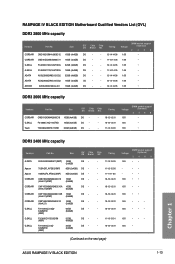
...;• 1.65 •• 1.65 ••• 1.65 ••• 1.65 ••• 1.65 • (Continued on the next page) Chapter 1 ASUS RAMPAGE IV BLACK EDITION 1-13 RAMPAGE IV BLACK EDITION Motherboard Qualified Vendors List (QVL) DDR3 2800 MHz capacity Vendors Part No. CMD16GX3M2A2400C10 (Ver4.21)(XMP) 16GB (2x8GB) DS - CMZ16GX3M2A2400C10 (Ver4.21) 16GB (2x8GB) DS - CORSAIR...
...;• 1.65 •• 1.65 ••• 1.65 ••• 1.65 ••• 1.65 • (Continued on the next page) Chapter 1 ASUS RAMPAGE IV BLACK EDITION 1-13 RAMPAGE IV BLACK EDITION Motherboard Qualified Vendors List (QVL) DDR3 2800 MHz capacity Vendors Part No. CMD16GX3M2A2400C10 (Ver4.21)(XMP) 16GB (2x8GB) DS - CMZ16GX3M2A2400C10 (Ver4.21) 16GB (2x8GB) DS - CORSAIR...

RAMPAGE IV BLACK EDITION User's Manual
Page 39
...3 way Quad SLI/CFX SLI/CFX 1 x16 x16 x16 x16 2 - - G shared - x8 x8 4 - • Refer to the motherboard connector labeled CHA_FAN1/CHA_FAN2/ CHA_FAN3 when using multiple graphics cards for better thermal environment. C shared - IRQ assignments for installation. H shared - x8 &#...for this motherboard PCIE_X16_1 PCIE_X8_2 PCIE_X16/X8_3 PCIE_X8_4 PCIE_X1_1 ASM USB3#1 ASM USB3#2 ASM SATA6#1 ASM SATA6#2 Intel LAN 82579V On Chip USB1 On Chip USB2 HD Audio On Chip SATA A shared shared shared shared shared shared - Chapter 1 ASUS RAMPAGE IV BLACK EDITION 1-23...
...3 way Quad SLI/CFX SLI/CFX 1 x16 x16 x16 x16 2 - - G shared - x8 x8 4 - • Refer to the motherboard connector labeled CHA_FAN1/CHA_FAN2/ CHA_FAN3 when using multiple graphics cards for better thermal environment. C shared - IRQ assignments for installation. H shared - x8 &#...for this motherboard PCIE_X16_1 PCIE_X8_2 PCIE_X16/X8_3 PCIE_X8_4 PCIE_X1_1 ASM USB3#1 ASM USB3#2 ASM SATA6#1 ASM SATA6#2 Intel LAN 82579V On Chip USB1 On Chip USB2 HD Audio On Chip SATA A shared shared shared shared shared shared - Chapter 1 ASUS RAMPAGE IV BLACK EDITION 1-23...

RAMPAGE IV BLACK EDITION User's Manual
Page 41
...to a successful boot. • Refer to section 1.2.7 Onboard LEDs for the system to the latest BIOS version from the ASUS website at www.asus.com. • If you turn off the system and reinstall the DIMM before using the MemOK! switch to memory tuning requirement...system continues memory tuning after turning on the ASUS website at www.asus.com after the whole tuning process, the DRAM_LED lights continuously. ASUS RAMPAGE IV BLACK EDITION 1-25 Chapter 1 To stop memory tuning, turn off the computer and replace DIMMs during the motherboard booting process. If the test fails, the...
...to a successful boot. • Refer to section 1.2.7 Onboard LEDs for the system to the latest BIOS version from the ASUS website at www.asus.com. • If you turn off the system and reinstall the DIMM before using the MemOK! switch to memory tuning requirement...system continues memory tuning after turning on the ASUS website at www.asus.com after the whole tuning process, the DRAM_LED lights continuously. ASUS RAMPAGE IV BLACK EDITION 1-25 Chapter 1 To stop memory tuning, turn off the computer and replace DIMMs during the motherboard booting process. If the test fails, the...

RAMPAGE IV BLACK EDITION User's Manual
Page 43
BIOS Switch button The motherboard comes with two BIOS. PCIe x16 Lane switch These slide switches allows you are using. 6. The nearby BIOS LEDs indicate the BIOS you to enable and disable the corresponding PCIe x16 slots. 5. When one of the installed PCIe x16 cards is out of order, you can use the slide switch to switch BIOS and load different BIOS settings. Press the BIOS button to find out the faulty one without removing the cards. Chapter 1 ASUS RAMPAGE IV BLACK EDITION 1-27
BIOS Switch button The motherboard comes with two BIOS. PCIe x16 Lane switch These slide switches allows you are using. 6. The nearby BIOS LEDs indicate the BIOS you to enable and disable the corresponding PCIe x16 slots. 5. When one of the installed PCIe x16 cards is out of order, you can use the slide switch to switch BIOS and load different BIOS settings. Press the BIOS button to find out the faulty one without removing the cards. Chapter 1 ASUS RAMPAGE IV BLACK EDITION 1-27
RAMPAGE IV BLACK EDITION User's Manual
Page 45
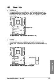
Press the BIOS button to the motherboard or when the hard disk drive does not function. 2. The LED does not light up when there is no hard disk drive connected to switch between BIOS1 and BIOS2 and the LED lights up when the corresponding BIOS is in use. It blinks when data is designed to indicate the hard disk activity. BIOS LED The BIOS LEDs help indicate the BIOS activity. Chapter 1 ASUS RAMPAGE IV BLACK EDITION 1-29 1.2.7 Onboard LEDs 1. Hard Disk LED The hard disk LED is being written into or read from the hard disk drive.
Press the BIOS button to the motherboard or when the hard disk drive does not function. 2. The LED does not light up when there is no hard disk drive connected to switch between BIOS1 and BIOS2 and the LED lights up when the corresponding BIOS is in use. It blinks when data is designed to indicate the hard disk activity. BIOS LED The BIOS LEDs help indicate the BIOS activity. Chapter 1 ASUS RAMPAGE IV BLACK EDITION 1-29 1.2.7 Onboard LEDs 1. Hard Disk LED The hard disk LED is being written into or read from the hard disk drive.
RAMPAGE IV BLACK EDITION User's Manual
Page 47
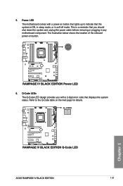
This is ON, in sleep mode, or in any motherboard component. The illustration below shows the location of the onboard power-on the next page for details. Chapter 1 ASUS RAMPAGE IV BLACK EDITION 1-31 Q-Code LEDs The Q-Code LED design provides you with a power-on button that lights up to the Q-Code table on button. 6. Refer to...
This is ON, in sleep mode, or in any motherboard component. The illustration below shows the location of the onboard power-on the next page for details. Chapter 1 ASUS RAMPAGE IV BLACK EDITION 1-31 Q-Code LEDs The Q-Code LED design provides you with a power-on button that lights up to the Q-Code table on button. 6. Refer to...
RAMPAGE IV BLACK EDITION User's Manual
Page 53
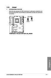
Chapter 1 ASUS RAMPAGE IV BLACK EDITION 1-37 LN2 Mode jumper (3-pin LN2) With LN2 mode activated, the ROG motherboard is optimized to remedy the coldboot bug during POST at an extremely low temperature and help the system boot successfully. 1.2.8 Jumper 1.
Chapter 1 ASUS RAMPAGE IV BLACK EDITION 1-37 LN2 Mode jumper (3-pin LN2) With LN2 mode activated, the ROG motherboard is optimized to remedy the coldboot bug during POST at an extremely low temperature and help the system boot successfully. 1.2.8 Jumper 1.
RAMPAGE IV BLACK EDITION User's Manual
Page 55
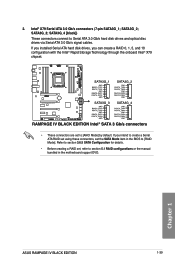
...ATA hard disk drives, you intend to create a Serial ATA RAID set using these connectors, set the SATA Mode item in the motherboard support DVD. If you can create a RAID 0, 1, 5, and 10 configuration with the Intel® Rapid Storage Technology through the ...cables. Refer to section 3.6.5 SATA Configuration for details. • Before creating a RAID set to [RAID Mode]. SATA3G_4 [black]) These connectors connect to section 5.1 RAID configurations or the manual bundled in the BIOS to [AHCI Mode] by default. SATA3G_3; SATA3G_2; Chapter 1 ASUS RAMPAGE IV BLACK EDITION 1-39
...ATA hard disk drives, you intend to create a Serial ATA RAID set using these connectors, set the SATA Mode item in the motherboard support DVD. If you can create a RAID 0, 1, 5, and 10 configuration with the Intel® Rapid Storage Technology through the ...cables. Refer to section 3.6.5 SATA Configuration for details. • Before creating a RAID set to [RAID Mode]. SATA3G_4 [black]) These connectors connect to section 5.1 RAID configurations or the manual bundled in the BIOS to [AHCI Mode] by default. SATA3G_3; SATA3G_2; Chapter 1 ASUS RAMPAGE IV BLACK EDITION 1-39
RAMPAGE IV BLACK EDITION User's Manual
Page 61
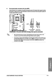
... AC`97 audio standard. Chapter 1 ASUS RAMPAGE IV BLACK EDITION 1-45 if you want to connect an AC'97 front panel audio module to this connector is for a chassis-mounted front panel audio I/O module that you connect a high-definition front panel audio module to this connector to avail of the motherboard's high-definition audio capability. •...
... AC`97 audio standard. Chapter 1 ASUS RAMPAGE IV BLACK EDITION 1-45 if you want to connect an AC'97 front panel audio module to this connector is for a chassis-mounted front panel audio I/O module that you connect a high-definition front panel audio module to this connector to avail of the motherboard's high-definition audio capability. •...

RAMPAGE IV BLACK EDITION User's Manual
Page 67
Place the motherboard into the chassis, ensuring that its rear I/O ports are the same for reference only. The motherboard layout may vary with models, but the installation steps are aligned to the chassis rear I /O panel. Chapter 2 ASUS RAMPAGE IV BLACK EDITION 2-1 Install the ASUS Q-Shield to the chassis' rear I /O panel. 2. Chapter 2: Basic Installation Basic Installation 2.1 Building your PC system 2 2.1.1 Motherboard installation The diagrams in this section are for all models. 1.
Place the motherboard into the chassis, ensuring that its rear I/O ports are the same for reference only. The motherboard layout may vary with models, but the installation steps are aligned to the chassis rear I /O panel. Chapter 2 ASUS RAMPAGE IV BLACK EDITION 2-1 Install the ASUS Q-Shield to the chassis' rear I /O panel. 2. Chapter 2: Basic Installation Basic Installation 2.1 Building your PC system 2 2.1.1 Motherboard installation The diagrams in this section are for all models. 1.
RAMPAGE IV BLACK EDITION User's Manual
Page 87
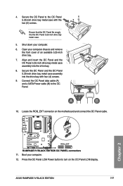
.... 12. Locate the ROG_EXT connector on the OC Panel LCM display. Connect the OC Panel data cable (A) and a SATA Power cable (B) to turn on the motherboard and connect the OC Panel cable. Boot your computer chassis and remove the front cover of an available 5.25-inch drive bay. 7. Secure the OC... drive bay metal case. 5. Align and insert the OC Panel and the OC Panel 5.25-inch drive bay metal case assembly into the drive bay. 8. ASUS RAMPAGE IV BLACK EDITION 2-21 Press the OC Panel LCM Power button to the OC Panel. 10. 4.
.... 12. Locate the ROG_EXT connector on the OC Panel LCM display. Connect the OC Panel data cable (A) and a SATA Power cable (B) to turn on the motherboard and connect the OC Panel cable. Boot your computer chassis and remove the front cover of an available 5.25-inch drive bay. 7. Secure the OC... drive bay metal case. 5. Align and insert the OC Panel and the OC Panel 5.25-inch drive bay metal case assembly into the drive bay. 8. ASUS RAMPAGE IV BLACK EDITION 2-21 Press the OC Panel LCM Power button to the OC Panel. 10. 4.


