

PRL-DLS User Manual
Page 18
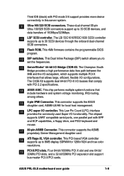
..., the PRL-DLS motherboard supports up to 4GB of system memory using PC2100/1600 registered ECC DDR DIMMs. The ultra-fast 200MHz memory bus doubles the speed of the PC100 SDRAM to -peer transactions between PCI buses and provides options for intelligent I /O bandwidth for the next generation 64-bit PCI-X cards that provide high-speed data transfer interfaces. Advanced 64-bit PCI-X slots The 64-bit/100MHz PCI-X slots onboard maximizes I /O and server management cards. The PCI-X specification...
..., the PRL-DLS motherboard supports up to 4GB of system memory using PC2100/1600 registered ECC DDR DIMMs. The ultra-fast 200MHz memory bus doubles the speed of the PC100 SDRAM to -peer transactions between PCI buses and provides options for intelligent I /O bandwidth for the next generation 64-bit PCI-X cards that provide high-speed data transfer interfaces. Advanced 64-bit PCI-X slots The 64-bit/100MHz PCI-X slots onboard maximizes I /O and server management cards. The PCI-X specification...
PRL-DLS User Manual
Page 21
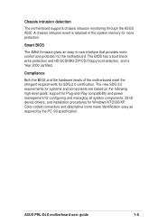
...-Play compatibility and power management for configuring and managing all system components, 32-bit device drivers, and installation procedures for SDG 2.0 certification. ASUS PRL-DLS motherboard user guide 1-5 Compliance Both the BIOS and the hardware levels of the motherboard meet the stringent requirements for Windows NT/2000/XP. Color-coded connectors and descriptive icons make identification easy as required by the PC '99 specification. Chassis intrusion detection The motherboard supports chassis intrusion monitoring through the ASUS ASIC. A chassis intrusion event is Year...
...-Play compatibility and power management for configuring and managing all system components, 32-bit device drivers, and installation procedures for SDG 2.0 certification. ASUS PRL-DLS motherboard user guide 1-5 Compliance Both the BIOS and the hardware levels of the motherboard meet the stringent requirements for Windows NT/2000/XP. Color-coded connectors and descriptive icons make identification easy as required by the PC '99 specification. Chassis intrusion detection The motherboard supports chassis intrusion monitoring through the ASUS ASIC. A chassis intrusion event is Year...

PRL-DLS User Manual
Page 24
...; processors with up to LPC (Low Pin Count) Bridge and integrates PCI master/slave functions, DMA controller, ATA100 IDE interface, USB contoller, SMBus host, ACPI and other integral functions. 8 IDE connectors. A 604-pin surface mount, Zero Insertion Force (ZIF) socket for the floppy disk drive. 1.4.2 Core specifications 1 604-pin CPU sockets. The GCSL device interfaces directly to 3.2GB/s data transfer rate. 2 8-pin 12V SSI power connector.
...; processors with up to LPC (Low Pin Count) Bridge and integrates PCI master/slave functions, DMA controller, ATA100 IDE interface, USB contoller, SMBus host, ACPI and other integral functions. 8 IDE connectors. A 604-pin surface mount, Zero Insertion Force (ZIF) socket for the floppy disk drive. 1.4.2 Core specifications 1 604-pin CPU sockets. The GCSL device interfaces directly to 3.2GB/s data transfer rate. 2 8-pin 12V SSI power connector.
PRL-DLS User Manual
Page 25
... mode 3/4 support provides more device connectivity in this server system. 9 Ultra-160/320 SCSI connectors. This Dual Inline Package (DIP) switch allows you to 8MB display SDRAM for local host management. 16 LPC super I /O configurations. This chip performs multiple system functions that allows large, efficient, flexible I /O controller. The chipset supports UART compatible serial ports, one 64-bit/ 33MHz PCI slots, and a 32-bit/33MHz PCI expansion slot support bus master PCI-X/PCI cards. This connector supports the ASMB proprietary Server Management...
... mode 3/4 support provides more device connectivity in this server system. 9 Ultra-160/320 SCSI connectors. This Dual Inline Package (DIP) switch allows you to 8MB display SDRAM for local host management. 16 LPC super I /O configurations. This chip performs multiple system functions that allows large, efficient, flexible I /O controller. The chipset supports UART compatible serial ports, one 64-bit/ 33MHz PCI slots, and a 32-bit/33MHz PCI expansion slot support bus master PCI-X/PCI cards. This connector supports the ASMB proprietary Server Management...
PRL-DLS User Manual
Page 39
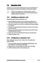
... necessary hardware settings for the expansion card. Remove the bracket opposite the slot that they support. Install the software drivers for the card. 2. Make sure to unplug the power cord before adding or removing expansion cards. The following subsections describe the slots and the expansion cards that you intend to the chassis with the screw you physical injury and damage motherboard components. 2.6.1 Installing an expansion card Follow these steps to install an expansion card. 1. ASUS PRL-DLS motherboard user guide 2-11 2.6 Expansion slots In...
... necessary hardware settings for the expansion card. Remove the bracket opposite the slot that they support. Install the software drivers for the card. 2. Make sure to unplug the power cord before adding or removing expansion cards. The following subsections describe the slots and the expansion cards that you intend to the chassis with the screw you physical injury and damage motherboard components. 2.6.1 Installing an expansion card Follow these steps to install an expansion card. 1. ASUS PRL-DLS motherboard user guide 2-11 2.6 Expansion slots In...
PRL-DLS User Manual
Page 48
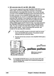
... you connect non-UltraDMA/100/66 devices to the hard disk documentation for the primary IDE connector and another UltraDMA/100/66 cable. You may configure two hard disks to PIN 1. This prevents incorrect orientation when you must configure the second drive as a slave device by setting its jumper accordingly. The UltraDMA/66 cable included in the motherboard package also supports UltraDMA/100. 2-20 Chapter 2: Hardware information PRL-DLS ® PRL-DLS IDE Connectors...
... you connect non-UltraDMA/100/66 devices to the hard disk documentation for the primary IDE connector and another UltraDMA/100/66 cable. You may configure two hard disks to PIN 1. This prevents incorrect orientation when you must configure the second drive as a slave device by setting its jumper accordingly. The UltraDMA/66 cable included in the motherboard package also supports UltraDMA/100. 2-20 Chapter 2: Hardware information PRL-DLS ® PRL-DLS IDE Connectors...
PRL-DLS User Manual
Page 56
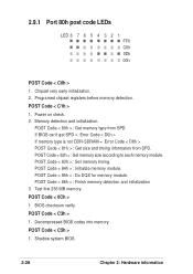
... memory module. Decompressed BIOS codes into memory. 2.9.1 Port 80h post code LEDs LED 8 7 6 5 4 3 2 1 FFh C0h 0Dh 00h POST Code < C0h > 1. If BIOS can't get SPD = Error Code < D0h > If memory type is not DDR-SDRAM = Error Code < D8h > POST Code < 81h > : Get size and timing information from SPD. POST Code < 85h > : Do DQS for memory module. POST Code < 86h > : Finish memory detection and initialization 3. Test first 256 MB memory. POST Code < C1h > 1. POST Code < 82h > : Set memory size according to each memory module. Power on check. 2. POST Code < 83h > : Set memory...
... memory module. Decompressed BIOS codes into memory. 2.9.1 Port 80h post code LEDs LED 8 7 6 5 4 3 2 1 FFh C0h 0Dh 00h POST Code < C0h > 1. If BIOS can't get SPD = Error Code < D0h > If memory type is not DDR-SDRAM = Error Code < D8h > POST Code < 81h > : Get size and timing information from SPD. POST Code < 85h > : Do DQS for memory module. POST Code < 86h > : Finish memory detection and initialization 3. Test first 256 MB memory. POST Code < C1h > 1. POST Code < 82h > : Set memory size according to each memory module. Power on check. 2. POST Code < 83h > : Set memory...
PRL-DLS User Manual
Page 59
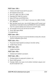
Setup ACPITable and ACPINVS Size. 6. Check USB Legacy Mode. 10. POST Code < 3Eh > 1. Programed chipset registers accroding to tell whether individual catagory error should be detected correctly after onboard memory configuration (just return). Installed floppy devices. Installed hard disks. Initialized and installed co-processor. Initialize and install mouse and 40: area stuff... 2. According to decrease Ext_MEM_FOUND, EXT_MEMORY. 7. Then fill in G_RAM. 4. POST Code < 4Eh > 1. After extended memory test, copy all ACPI tables. 8. Checked whether...
Setup ACPITable and ACPINVS Size. 6. Check USB Legacy Mode. 10. POST Code < 3Eh > 1. Programed chipset registers accroding to tell whether individual catagory error should be detected correctly after onboard memory configuration (just return). Installed floppy devices. Installed hard disks. Initialized and installed co-processor. Initialize and install mouse and 40: area stuff... 2. According to decrease Ext_MEM_FOUND, EXT_MEMORY. 7. Then fill in G_RAM. 4. POST Code < 4Eh > 1. After extended memory test, copy all ACPI tables. 8. Checked whether...
PRL-DLS User Manual
Page 74
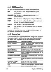
... various setup menus. 4.2.1 BIOS menu bar The top of the Setup screen is a legend bar. SERVER Use this menu to set server-related items EXIT Use this menu to exit the current menu or to configure power management features. ADVANCED Use this menu to exit the Setup program. POWER Use this menu to enable and make changes to the basic system configuration. BOOT Use this menu to make changes to locate and load the Operating System. The keys in the BIOS Setup Jumps...
... various setup menus. 4.2.1 BIOS menu bar The top of the Setup screen is a legend bar. SERVER Use this menu to set server-related items EXIT Use this menu to exit the current menu or to configure power management features. ADVANCED Use this menu to exit the Setup program. POWER Use this menu to enable and make changes to the basic system configuration. BOOT Use this menu to make changes to locate and load the Operating System. The keys in the BIOS Setup Jumps...
PRL-DLS User Manual
Page 84
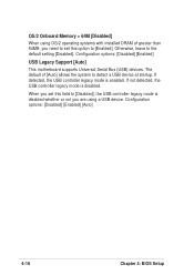
... 4-16 Chapter 4: BIOS Setup When you set this field to [Disabled], the USB controller legacy mode is disabled whether or not you need to set this option to [Enabled]. The default of greater than 64MB, you are using OS/2 operating systems with installed DRAM of [Auto] allows the system to the default setting [Disabled]. If detected, the USB controller legacy mode is disabled. OS/2 Onboard Memory > 64M [Disabled] When using a USB device. Configuration options: [Disabled] [Enabled] USB Legacy Support [Auto] This motherboard supports Universal Serial Bus (USB) devices.
... 4-16 Chapter 4: BIOS Setup When you set this field to [Disabled], the USB controller legacy mode is disabled whether or not you need to set this option to [Enabled]. The default of greater than 64MB, you are using OS/2 operating systems with installed DRAM of [Auto] allows the system to the default setting [Disabled]. If detected, the USB controller legacy mode is disabled. OS/2 Onboard Memory > 64M [Disabled] When using a USB device. Configuration options: [Disabled] [Enabled] USB Legacy Support [Auto] This motherboard supports Universal Serial Bus (USB) devices.

PRL-DLS User Manual
Page 96
... SCSI controllers or SCSI cards, RAID cards, and other devices on add-on an operating system but requires a specific BIOS code for support. Configuration options: [No] [Yes] 4-28 Chapter 4: BIOS Setup Bootable FDDs, ATA HDD, ATAPI CD-ROM, ATA ZIP, and ATA MO drives are present onboard: [Disabled] [Floppy] [HDD] [CD-ROM] [LAN Option ROM] [SCSI] 3rd Boot : (BCV) [None] This field allows you to select a Boot Connection Vector (BCV) device to configure the PCI bus slots instead of interrupt settings, keep the default setting...
... SCSI controllers or SCSI cards, RAID cards, and other devices on add-on an operating system but requires a specific BIOS code for support. Configuration options: [No] [Yes] 4-28 Chapter 4: BIOS Setup Bootable FDDs, ATA HDD, ATAPI CD-ROM, ATA ZIP, and ATA MO drives are present onboard: [Disabled] [Floppy] [HDD] [CD-ROM] [LAN Option ROM] [SCSI] 3rd Boot : (BCV) [None] This field allows you to select a Boot Connection Vector (BCV) device to configure the PCI bus slots instead of interrupt settings, keep the default setting...
PRL-DLS User Manual
Page 97
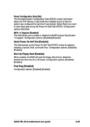
... to enable or disable the MultiProcessor Specification 1.4 support. Configuration options: [Disabled] [Enabled] Boot Up Floppy Seek [Enabled] When enabled, the BIOS will seek the floppy disk drive to clear these data during the Power-On-Self-Test (POST). Configuration options: [Disabled] [Enabled] Quick Power On Self Test [Enabled] This field speeds up the Power-On-Self Test (POST) routine by skipping retesting a second, third, and fourth time. Configuration options: [Disabled] [Enabled] Post Diag [Disabled] Configuration options: [Disabled] [Enabled] ASUS PRL-DLS motherboard user guide...
... to enable or disable the MultiProcessor Specification 1.4 support. Configuration options: [Disabled] [Enabled] Boot Up Floppy Seek [Enabled] When enabled, the BIOS will seek the floppy disk drive to clear these data during the Power-On-Self-Test (POST). Configuration options: [Disabled] [Enabled] Quick Power On Self Test [Enabled] This field speeds up the Power-On-Self Test (POST) routine by skipping retesting a second, third, and fourth time. Configuration options: [Disabled] [Enabled] Post Diag [Disabled] Configuration options: [Disabled] [Enabled] ASUS PRL-DLS motherboard user guide...
PRL-DLS User Manual
Page 99
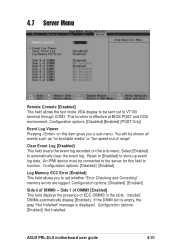
... to automatically clear the event log. ASUS PRL-DLS motherboard user guide 4-31 Configuration options: [Disabled] [Enabled] Log Memory ECC Error [Enabled] This field allows you a sub-menu. You will be shown all events such as "no bootable media" or "fan speed out of ECC DIMMS in the slots. Side 1 of DIMM3 [Enabled] This field displays the presence of range". Select [Enabled] to set whether "Error Checking and Correcting" memory errors are logged. An IPMI device must be connected to function. Reset to [Disabled] to...
... to automatically clear the event log. ASUS PRL-DLS motherboard user guide 4-31 Configuration options: [Disabled] [Enabled] Log Memory ECC Error [Enabled] This field allows you a sub-menu. You will be shown all events such as "no bootable media" or "fan speed out of ECC DIMMS in the slots. Side 1 of DIMM3 [Enabled] This field displays the presence of range". Select [Enabled] to set whether "Error Checking and Correcting" memory errors are logged. An IPMI device must be connected to function. Reset to [Disabled] to...
PRL-DLS User Manual
Page 107
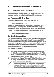
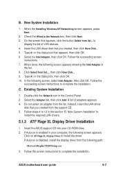
... 4.0 installation. Windows NT automatically adds the driver to the registry and copies the driver to allow CD-ROM booting when using SCSI-interface CD-ROM drive. 2. LSI BIOS settings may need to be done or else the new driver installed from the Windows NT CD-ROM. 5.1 Microsoft® Windows® NT Server 4.0 5.1.1 LSI® SCSI Driver Installation Windows NT 4.0 do not have drivers for Windows NT drivers. When the screen displays "Windows NT Setup", immediately press the F6 key. ASUS motherboard user guide 5-3 A. New System Installation...
... 4.0 installation. Windows NT automatically adds the driver to the registry and copies the driver to allow CD-ROM booting when using SCSI-interface CD-ROM drive. 2. LSI BIOS settings may need to be done or else the new driver installed from the Windows NT CD-ROM. 5.1 Microsoft® Windows® NT Server 4.0 5.1.1 LSI® SCSI Driver Installation Windows NT 4.0 do not have drivers for Windows NT drivers. When the screen displays "Windows NT Setup", immediately press the F6 key. ASUS motherboard user guide 5-3 A. New System Installation...

PRL-DLS User Manual
Page 108
... mass storage device detection. Press S to skip automatic detection and perform a manual selection. Move the highlight bar to Setup screen appears. Boot Floppy Disk Installation 1. B2. Press Enter when the Welcome to Other and press Enter. 8. When a screen displays the SCSI adapters found, select S to proceed. 5. When prompted for the manufacturer-supplied hardware support disk, insert the appropriate LSI driver disk containing the Windows NT driver required to support your LSI adapter(s) and...
... mass storage device detection. Press S to skip automatic detection and perform a manual selection. Move the highlight bar to Setup screen appears. Boot Floppy Disk Installation 1. B2. Press Enter when the Welcome to Other and press Enter. 8. When a screen displays the SCSI adapters found, select S to proceed. 5. When prompted for the manufacturer-supplied hardware support disk, insert the appropriate LSI driver disk containing the Windows NT driver required to support your LSI adapter(s) and...
PRL-DLS User Manual
Page 109
... it before adding the new driver. Click the Have Disk button. 7. The path to load additional drives. ASUS motherboard user guide 5-5 Depending on the driver being installed, Symbios Ultra3 PCI SCSI Driver is shown highlighted. Press Enter to remove this point, simply follow the Microsoft Windows NT installation procedure. Scroll up and select: IDE CD-ROM (ATAPI 1.2/PCI IDE Controller. Select OK when the Remove Driver message prompts: "Are you sure you...
... it before adding the new driver. Click the Have Disk button. 7. The path to load additional drives. ASUS motherboard user guide 5-5 Depending on the driver being installed, Symbios Ultra3 PCI SCSI Driver is shown highlighted. Press Enter to remove this point, simply follow the Microsoft Windows NT installation procedure. Scroll up and select: IDE CD-ROM (ATAPI 1.2/PCI IDE Controller. Select OK when the Remove Driver message prompts: "Are you sure you...
PRL-DLS User Manual
Page 111
... OK. 10. Instead, insert the LAN driver disk that appears, then click OK. 6. Select the Intel Adapter, then click OK. Select the Adapter tab, then click Add. Click on ATI Rage XL Display Driver to complete the installation. If Autorun is disabled, install the display driver from list..., then click Have Disk... 9. Do not select an adapter from the support CD. 5. ASUS motherboard user guide 5-7 to 12 in the dialog box...
... OK. 10. Instead, insert the LAN driver disk that appears, then click OK. 6. Select the Intel Adapter, then click OK. Select the Adapter tab, then click Add. Click on ATI Rage XL Display Driver to complete the installation. If Autorun is disabled, install the display driver from list..., then click Have Disk... 9. Do not select an adapter from the support CD. 5. ASUS motherboard user guide 5-7 to 12 in the dialog box...
PRL-DLS User Manual
Page 113
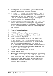
... scrolling the display to support your LSI adapter(s) and press Enter. C. The Upgrade Device Driver Wizard begins. Insert the appropriate LSI driver disk that a non-signed driver is checked. Existing System Installation 1. The entry for the selected adapter. 10. At this driver is not desired or click Yes to the Windows 2000 Setup screen. A list of the SCSI and RAID controllers line. Information on the currently installed driver is shown highlighted. ASUS motherboard user guide 5-9 4.
... scrolling the display to support your LSI adapter(s) and press Enter. C. The Upgrade Device Driver Wizard begins. Insert the appropriate LSI driver disk that a non-signed driver is checked. Existing System Installation 1. The entry for the selected adapter. 10. At this driver is not desired or click Yes to the Windows 2000 Setup screen. A list of the SCSI and RAID controllers line. Information on the currently installed driver is shown highlighted. ASUS motherboard user guide 5-9 4.

PRL-DLS User Manual
Page 115
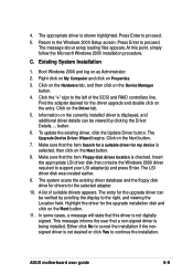
... and log on Update Drivers. 7. Select the Driver tab and click on as Administrator. 2. Select Display a list of the known drivers for supporting the onboard ATI RAGE XL graphics controller chipset. 5.2.4 Enabling ATA100 Feature in the Control Panel. Click on Other Devices. 5. Highlight Ethernet Controller, then click the right mouse button and select Properties. 6. Click on Device Manager, then on the Start button. Follow the succeeding instructions to Windows 2000 Service Pack 2. ASUS motherboard user guide...
... and log on Update Drivers. 7. Select the Driver tab and click on as Administrator. 2. Select Display a list of the known drivers for supporting the onboard ATI RAGE XL graphics controller chipset. 5.2.4 Enabling ATA100 Feature in the Control Panel. Click on Other Devices. 5. Highlight Ethernet Controller, then click the right mouse button and select Properties. 6. Click on Device Manager, then on the Start button. Follow the succeeding instructions to Windows 2000 Service Pack 2. ASUS motherboard user guide...

PRL-DLS User Manual
Page 130
... network controller during installation. adapters. Run 'netconfig' and add the adapters. If you want the kernel environment rebuilt (y/n)?" Exit 'netconfig' and choose to relink the kernel. 3. At the command prompt, type: # reboot (or init 6) 5-26 Chapter 5: OS Installation To activate the new kernel, you must reboot the system. After the installation of these settings, choose 'Advanced Options' and set the speed and duplex modes. By default, the driver automatically detects...
... network controller during installation. adapters. Run 'netconfig' and add the adapters. If you want the kernel environment rebuilt (y/n)?" Exit 'netconfig' and choose to relink the kernel. 3. At the command prompt, type: # reboot (or init 6) 5-26 Chapter 5: OS Installation To activate the new kernel, you must reboot the system. After the installation of these settings, choose 'Advanced Options' and set the speed and duplex modes. By default, the driver automatically detects...


