
PP-DLW User Manual
Page 1
Motherboard PP-DLW User Guide
Motherboard PP-DLW User Guide

PP-DLW User Manual
Page 3
Features Contents Notices vi Safety information vii About this guide viii ASUS contact information x PP-DLW specifications summary xi Chapter 1: Product introduction 1.1 Welcome 1-1 1.2 Package contents 1-1 1.3 Special features 1-2 1.3.1 Product highlights 1-2 1.3.2 Value-added solutions 1-4 Chapter 2: Hardware information 2.1 Motherboard installation 2-1 2.1.1 Placement direction 2-1 2.1.2 Screw holes 2-1 2.2 Motherboard layout 2-2 2.3 Before you proceed 2-3 2.4 Central Processing Unit (CPU 2-4 2.4.1 Overview 2-4 2.4.2 Installing the CPU 2-5 2.4.3 Installing the...
Features Contents Notices vi Safety information vii About this guide viii ASUS contact information x PP-DLW specifications summary xi Chapter 1: Product introduction 1.1 Welcome 1-1 1.2 Package contents 1-1 1.3 Special features 1-2 1.3.1 Product highlights 1-2 1.3.2 Value-added solutions 1-4 Chapter 2: Hardware information 2.1 Motherboard installation 2-1 2.1.1 Placement direction 2-1 2.1.2 Screw holes 2-1 2.2 Motherboard layout 2-2 2.3 Before you proceed 2-3 2.4 Central Processing Unit (CPU 2-4 2.4.1 Overview 2-4 2.4.2 Installing the CPU 2-5 2.4.3 Installing the...

PP-DLW User Manual
Page 7
If you are not sure about the voltage of the electrical outlet you add a device. • Before connecting or removing signal cables from the motherboard, ensure that came with the product, contact a qualified service technician or your dealer immediately. • To avoid short circuits, keep paper clips, screws, and staples ...
If you are not sure about the voltage of the electrical outlet you add a device. • Before connecting or removing signal cables from the motherboard, ensure that came with the product, contact a qualified service technician or your dealer immediately. • To avoid short circuits, keep paper clips, screws, and staples ...
PP-DLW User Manual
Page 8
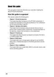
...2: Hardware information This chapter lists the hardware setup procedures that you need when installing the ASUS PP-DLW motherboard. It includes description of the switches, jumpers, and connectors on the motherboard. • Chapter 3: Powering up This chapter describes the power up sequence and gives information...is organized This manual contains the following parts: • Chapter 1: Product introduction This chapter describes the features of the PP-DLW motherboard. How this guide This user guide contains the information you have to change system settings through the BIOS Setup menus....
...2: Hardware information This chapter lists the hardware setup procedures that you need when installing the ASUS PP-DLW motherboard. It includes description of the switches, jumpers, and connectors on the motherboard. • Chapter 3: Powering up This chapter describes the power up sequence and gives information...is organized This manual contains the following parts: • Chapter 1: Product introduction This chapter describes the features of the PP-DLW motherboard. How this guide This user guide contains the information you have to change system settings through the BIOS Setup menus....

PP-DLW User Manual
Page 13
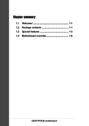
Chapter 1 This chapter describes the features of the motherboard and the new technology it supports. Product introduction It includes brief explanations of the special attributes of the PP-DLW motherboard.
Chapter 1 This chapter describes the features of the motherboard and the new technology it supports. Product introduction It includes brief explanations of the special attributes of the PP-DLW motherboard.
PP-DLW User Manual
Page 14
Chapter summary 1.1 Welcome 1-1 1.2 Package contents 1-1 1.3 Special features 1-2 1.4 Motherboard overview 1-6 ASUS PP-DLW motherboard
Chapter summary 1.1 Welcome 1-1 1.2 Package contents 1-1 1.3 Special features 1-2 1.4 Motherboard overview 1-6 ASUS PP-DLW motherboard
PP-DLW User Manual
Page 15
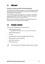
...your PP-DLW package for the following items. ASUS PP-DLW motherboard Extended ATX form factor: 12 in x 10.5 in (30.5 cm x 26.7 cm) ASUS PP-DLW support CD I/O shield 80-conductor ribbon cable for UltraDMA100/66/33 IDE drives Ribbon cable for buying the ASUS® PP-DLW motherboard! The ASUS PP-DLW motherboard delivers... a host of new features and latest technologies making it , check the items in your retailer. The PP-DLW incorporates dual Intel® Xeon™ processors in ...
...your PP-DLW package for the following items. ASUS PP-DLW motherboard Extended ATX form factor: 12 in x 10.5 in (30.5 cm x 26.7 cm) ASUS PP-DLW support CD I/O shield 80-conductor ribbon cable for UltraDMA100/66/33 IDE drives Ribbon cable for buying the ASUS® PP-DLW motherboard! The ASUS PP-DLW motherboard delivers... a host of new features and latest technologies making it , check the items in your retailer. The PP-DLW incorporates dual Intel® Xeon™ processors in ...

PP-DLW User Manual
Page 16
...fast 266MHz memory bus doubles the speed of its predecessor AGP 4X. 1.3 Special features 1.3.1 Product highlights Latest processor technology The PP-DLW motherboard supports the Intel® Xeon processor via dual 604-pin surface mount ZIF sockets. See page 2-4 for the latest 3D graphics...applications. DDR memory support Employing the Double Data Rate (DDR) memory technology, the PP-DLW motherboard supports up to offer a significant increase in performance. AGP Pro 8x/4X slot The motherboard supports the latest graphic architecture, the AGP Pro/8X interface (a.k.a. The processor features ...
...fast 266MHz memory bus doubles the speed of its predecessor AGP 4X. 1.3 Special features 1.3.1 Product highlights Latest processor technology The PP-DLW motherboard supports the Intel® Xeon processor via dual 604-pin surface mount ZIF sockets. See page 2-4 for the latest 3D graphics...applications. DDR memory support Employing the Double Data Rate (DDR) memory technology, the PP-DLW motherboard supports up to offer a significant increase in performance. AGP Pro 8x/4X slot The motherboard supports the latest graphic architecture, the AGP Pro/8X interface (a.k.a. The processor features ...
PP-DLW User Manual
Page 17
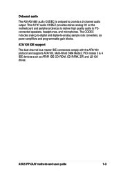
... and digital-to-analog sample rate converters, as ATAPI IDE CD-ROM, CD-R/RW, ZIP, and LS-120 drives. ASUS PP-DLW motherboard user guide 1-3 This AC'97 audio CODEC provides stereo analog I/O on the motherboard and peripheral devices to deliver high quality audio to provide a 2-channel audio output. ATA/100 IDE support The dual...
... and digital-to-analog sample rate converters, as ATAPI IDE CD-ROM, CD-R/RW, ZIP, and LS-120 drives. ASUS PP-DLW motherboard user guide 1-3 This AC'97 audio CODEC provides stereo analog I/O on the motherboard and peripheral devices to deliver high quality audio to provide a 2-channel audio output. ATA/100 IDE support The dual...
PP-DLW User Manual
Page 18
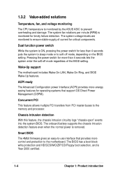
...is monitored for more control and protection to ensure stable supply of the BIOS setting. The system voltage levels are monitored to the motherboard. ACPI ready The Advanced Configuration power Interface (ACPI) provides more energy saving features for operating systems that provides more than 4 ... system BIOS. The BIOS has a boot block write protection and HD/SCSI/MO/ZIP/CD/Floppy boot selection, and is monitored by the ASUS ASIC to the memory and processor. 1.3.2 Value-added solutions Temperature, fan, and voltage monitoring The CPU temperature is Year 2000 certified. 1-4...
...is monitored for more control and protection to ensure stable supply of the BIOS setting. The system voltage levels are monitored to the motherboard. ACPI ready The Advanced Configuration power Interface (ACPI) provides more energy saving features for operating systems that provides more than 4 ... system BIOS. The BIOS has a boot block write protection and HD/SCSI/MO/ZIP/CD/Floppy boot selection, and is monitored by the ASUS ASIC to the memory and processor. 1.3.2 Value-added solutions Temperature, fan, and voltage monitoring The CPU temperature is Year 2000 certified. 1-4...

PP-DLW User Manual
Page 19
The new SDG 2.0 requirements for systems and components are based on the following high-level goals: support for Plug-and-Play compatibility and power management for configuring and managing all system components, 32-bit device drivers, and installation procedures for SDG 2.0 certification. ASUS PP-DLW motherboard user guide 1-5 Compliance Both the BIOS and the hardware levels of the motherboard meet the stringent requirements for Windows NT/2000/XP. Color-coded connectors and descriptive icons make identification easy as required by the PC '99 specification.
The new SDG 2.0 requirements for systems and components are based on the following high-level goals: support for Plug-and-Play compatibility and power management for configuring and managing all system components, 32-bit device drivers, and installation procedures for SDG 2.0 certification. ASUS PP-DLW motherboard user guide 1-5 Compliance Both the BIOS and the hardware levels of the motherboard meet the stringent requirements for Windows NT/2000/XP. Color-coded connectors and descriptive icons make identification easy as required by the PC '99 specification.

PP-DLW User Manual
Page 20
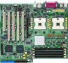
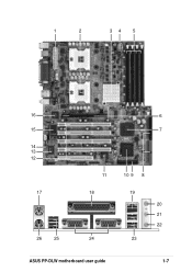
...Motherboard overview Before you avoid mistakes that may damage the board and its physical configuration and available features to PCI-X4) PCI slot (PCI1) 13. AGP Pro 8X slot 7. Intel® ICH4 I /O controller 16. Standby power LED 15. Line Out port 22. Serial ports 25. Floppy disk connector 10. ASUS...slots (PCI-X1 to facilitate the motherboard installation and future upgrades. Parallel port 19. IDE connectors 9. A sufficient knowledge of the motherboard specifications will also help you install the PP-DLW motherboard, familiarize yourself with its components. ...
...Motherboard overview Before you avoid mistakes that may damage the board and its physical configuration and available features to PCI-X4) PCI slot (PCI1) 13. AGP Pro 8X slot 7. Intel® ICH4 I /O controller 16. Standby power LED 15. Line Out port 22. Serial ports 25. Floppy disk connector 10. ASUS...slots (PCI-X1 to facilitate the motherboard installation and future upgrades. Parallel port 19. IDE connectors 9. A sufficient knowledge of the motherboard specifications will also help you install the PP-DLW motherboard, familiarize yourself with its components. ...
PP-DLW User Manual
Page 21
1 2 34 5 16 15 14 13 12 17 26 25 6 7 11 18 24 10 9 8 19 20 21 22 23 ASUS PP-DLW motherboard user guide 1-7
1 2 34 5 16 15 14 13 12 17 26 25 6 7 11 18 24 10 9 8 19 20 21 22 23 ASUS PP-DLW motherboard user guide 1-7
PP-DLW User Manual
Page 23
...a single-chip solution for a PS/2 mouse. 18 Parallel port. This LED lights up if there is a standby power on Motherboard (LOM) and Network Interface Card (NIC) applications. This port allows connection to turn off the system power before plugging or unplugging .... This chip performs multiple system functions that include hardware and system voltage monitoring, IRQ routing, among others. 14 Standby power LED. ASUS PP-DLW motherboard user guide 1-9 This 4Mb firmware hub contains the programmable BIOS program. 12 PCI-X/PCI slots. The I /O controller. The ICH4 communicates...
...a single-chip solution for a PS/2 mouse. 18 Parallel port. This LED lights up if there is a standby power on Motherboard (LOM) and Network Interface Card (NIC) applications. This port allows connection to turn off the system power before plugging or unplugging .... This chip performs multiple system functions that include hardware and system voltage monitoring, IRQ routing, among others. 14 Standby power LED. ASUS PP-DLW motherboard user guide 1-9 This 4Mb firmware hub contains the programmable BIOS program. 12 PCI-X/PCI slots. The I /O controller. The ICH4 communicates...

PP-DLW User Manual
Page 25
Hardware information It includes details on the switch/jumper settings and connector locations on the motherboard. Chapter 2 This chapter describes the hardware setup procedures that you have to perform when installing system components.
Hardware information It includes details on the switch/jumper settings and connector locations on the motherboard. Chapter 2 This chapter describes the hardware setup procedures that you have to perform when installing system components.
PP-DLW User Manual
Page 26
Chapter summary 2.1 Motherboard installation 2-1 2.2 Motherboard layout 2-2 2.3 Before you proceed 2-3 2.4 Central Processing Unit (CPU 2-4 2.5 System memory 2-8 2.6 Expansion slots 2-11 2.7 Jumpers 2-14 2.8 Connectors 2-18 ASUS PP-DLW motherboard
Chapter summary 2.1 Motherboard installation 2-1 2.2 Motherboard layout 2-2 2.3 Before you proceed 2-3 2.4 Central Processing Unit (CPU 2-4 2.5 System memory 2-8 2.6 Expansion slots 2-11 2.7 Jumpers 2-14 2.8 Connectors 2-18 ASUS PP-DLW motherboard
PP-DLW User Manual
Page 27
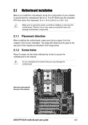
... the configuration of the chassis ASUS PP-DLW motherboard user guide 2-1 The PP-DLW uses the extended ATX form factor that measures 12 in x 10.5 in the image below. 2.1.2 Screw holes Place 9 screws into the chassis in the correct ... The edge with external ports goes to ensure that you physical injury and damage motherboard components. 2.1.1 Placement direction When installing the motherboard, make sure that the motherboard fits into it into the holes indicated by circles to secure the motherboard to the chassis. Failure to unplug the power cord before installing or removing the...
... the configuration of the chassis ASUS PP-DLW motherboard user guide 2-1 The PP-DLW uses the extended ATX form factor that measures 12 in x 10.5 in the image below. 2.1.2 Screw holes Place 9 screws into the chassis in the correct ... The edge with external ports goes to ensure that you physical injury and damage motherboard components. 2.1.1 Placement direction When installing the motherboard, make sure that the motherboard fits into it into the holes indicated by circles to secure the motherboard to the chassis. Failure to unplug the power cord before installing or removing the...

PP-DLW User Manual
Page 28
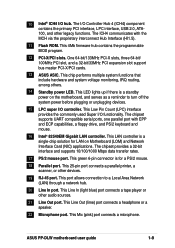
...) Bridge Hub J16 AUDIO_COM1 J18 PCI-X3 (64-bit, 100MHz 3V) LED4 ASUS ASIC with Hardware Monitor PCI-X4 (64-bit, 133MHz 3V) 4Mbit Flash BIOS J20 PCI1 (32-bit, 33MHz 5V) FAN5 GAME1 J26 J33 PP-DLW J25 J31 BATTERY1 Intel I/O Controller Hub (ICH4) BUZZ1 J21 J22 J23 J24 ...FLOPPY Primary IDE 26.7cm (10.5in) The audio and LAN features are grayed out in the above motherboard layout. 2-2 Chapter 2: Hardware information These components are optional.
...) Bridge Hub J16 AUDIO_COM1 J18 PCI-X3 (64-bit, 100MHz 3V) LED4 ASUS ASIC with Hardware Monitor PCI-X4 (64-bit, 133MHz 3V) 4Mbit Flash BIOS J20 PCI1 (32-bit, 33MHz 5V) FAN5 GAME1 J26 J33 PP-DLW J25 J31 BATTERY1 Intel I/O Controller Hub (ICH4) BUZZ1 J21 J22 J23 J24 ...FLOPPY Primary IDE 26.7cm (10.5in) The audio and LAN features are grayed out in the above motherboard layout. 2-2 Chapter 2: Hardware information These components are optional.
PP-DLW User Manual
Page 29
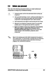
... as the power supply case, before removing or plugging in the bag that came with the component. 5. PP-DLW PP-DLW Onboard LED LED4 ON Standby Power OFF Powered Off ASUS PP-DLW motherboard user guide 2-3 Hold components by the edges to avoid touching the ICs on a grounded antistatic pad or ...in any motherboard component. When lit, the standby power LED (LED4) indicates that you should shut down the...
... as the power supply case, before removing or plugging in the bag that came with the component. 5. PP-DLW PP-DLW Onboard LED LED4 ON Standby Power OFF Powered Off ASUS PP-DLW motherboard user guide 2-3 Hold components by the edges to avoid touching the ICs on a grounded antistatic pad or ...in any motherboard component. When lit, the standby power LED (LED4) indicates that you should shut down the...
PP-DLW User Manual
Page 30
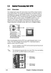
...integer instructions, and data transfer rate of the CPU into the socket may bend the pins and severely damage the CPU! The motherboard supports either one CPU, you are designed for the Intel Processor in CPU socket 1. This mark indicates the processor Pin 1 that...1 (outer socket) CPU Socket 2 (inner socket) 2-4 Chapter 2: Hardware information Incorrect installation of up to 4.2GBps/3.2GBps. Xeon™ Processor PP-DLW PP-DLW Socket 604 Gold Mark Note in the illustration that should match a specific corner of the CPU socket. The processor includes the Intel® NetBurst...
...integer instructions, and data transfer rate of the CPU into the socket may bend the pins and severely damage the CPU! The motherboard supports either one CPU, you are designed for the Intel Processor in CPU socket 1. This mark indicates the processor Pin 1 that...1 (outer socket) CPU Socket 2 (inner socket) 2-4 Chapter 2: Hardware information Incorrect installation of up to 4.2GBps/3.2GBps. Xeon™ Processor PP-DLW PP-DLW Socket 604 Gold Mark Note in the illustration that should match a specific corner of the CPU socket. The processor includes the Intel® NetBurst...


