PP-DLW User Manual
Page 11
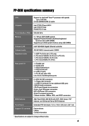
xi PP-DLW specifications summary CPU Chipsets Front Side Bus (FSB) Memory Onboard LAN Onboard audio Expansion slots Rear panel I/O Internal connectors BIOS features Form Factor Support CD contents Support for dual Intel® Xeon™ processor with speeds up to 3.06 GHz On-die 256KB/512KB L2 cache Intel E7505 (Placer) MCH Intel ICH4 I/O Hub P64H2 PCI-X Hub 533/400 MHz 4 x 184-pin DDR DIMM sockets Supports PC2100/PC1600 unbuffered/registered ECC/non-ECC DDR...
xi PP-DLW specifications summary CPU Chipsets Front Side Bus (FSB) Memory Onboard LAN Onboard audio Expansion slots Rear panel I/O Internal connectors BIOS features Form Factor Support CD contents Support for dual Intel® Xeon™ processor with speeds up to 3.06 GHz On-die 256KB/512KB L2 cache Intel E7505 (Placer) MCH Intel ICH4 I/O Hub P64H2 PCI-X Hub 533/400 MHz 4 x 184-pin DDR DIMM sockets Supports PC2100/PC1600 unbuffered/registered ECC/non-ECC DDR...
PP-DLW User Manual
Page 15
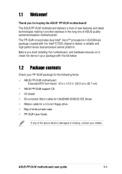
... devices on it another standout in (30.5 cm x 26.7 cm) ASUS PP-DLW support CD I/O shield 80-conductor ribbon cable for UltraDMA100/66/33 IDE drives Ribbon cable for a 3.5-inch floppy drive Bag of extra jumper caps PP-DLW User Guide If any of the above items is damaged or missing, contact your package with the Intel® E7505 chipset to deliver a reliable and high performance dual-processor server platform. ASUS PP-DLW motherboard user guide...
... devices on it another standout in (30.5 cm x 26.7 cm) ASUS PP-DLW support CD I/O shield 80-conductor ribbon cable for UltraDMA100/66/33 IDE drives Ribbon cable for a 3.5-inch floppy drive Bag of extra jumper caps PP-DLW User Guide If any of the above items is damaged or missing, contact your package with the Intel® E7505 chipset to deliver a reliable and high performance dual-processor server platform. ASUS PP-DLW motherboard user guide...
PP-DLW User Manual
Page 22
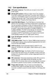
... 3.0 specification), and supports dual-channel DDR SDRAM interface for an ATX power supply. 5 DDR DIMM sockets. This connector accommodates the provided ribbon cable for an ATX power supply. 2 604-pin CPU sockets. This Accelerated Graphics (AGP) Pro slot supports 1.5V AGP 8X mode graphic cards to deliver up to prevent incorrect insertion of the connector is slotted to 8GB system memory using unbuffered/registered ECC/non-ECC PC2100/1600 DDR DIMMs. 6 AGP Pro 8X slot. One side of the floppy disk cable...
... 3.0 specification), and supports dual-channel DDR SDRAM interface for an ATX power supply. 5 DDR DIMM sockets. This connector accommodates the provided ribbon cable for an ATX power supply. 2 604-pin CPU sockets. This Accelerated Graphics (AGP) Pro slot supports 1.5V AGP 8X mode graphic cards to deliver up to prevent incorrect insertion of the connector is slotted to 8GB system memory using unbuffered/registered ECC/non-ECC PC2100/1600 DDR DIMMs. 6 AGP Pro 8X slot. One side of the floppy disk cable...
PP-DLW User Manual
Page 23
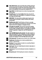
... Flash ROM. This 25-pin port connects a parallel printer, a scanner, or other legacy functions. This Mic (pink) port connects a microphone. This 4Mb firmware hub contains the programmable BIOS program. 12 PCI-X/PCI slots. This port allows connection to turn off the system power before plugging or unplugging devices. 15 LPC super I /O Controller Hub 4 (ICH4) component contains the primary PCI interface, LPC interface, USB 2.0, ATA100, and other devices. 19 RJ-45 port. ASUS PP-DLW motherboard user guide 1-9 The chipset provides a 32-bit...
... Flash ROM. This 25-pin port connects a parallel printer, a scanner, or other legacy functions. This Mic (pink) port connects a microphone. This 4Mb firmware hub contains the programmable BIOS program. 12 PCI-X/PCI slots. This port allows connection to turn off the system power before plugging or unplugging devices. 15 LPC super I /O Controller Hub 4 (ICH4) component contains the primary PCI interface, LPC interface, USB 2.0, ATA100, and other devices. 19 RJ-45 port. ASUS PP-DLW motherboard user guide 1-9 The chipset provides a 32-bit...
PP-DLW User Manual
Page 37
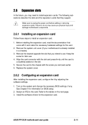
... BIOS settings, if any. Replace the system cover. 2.6.2 Configuring an expansion card After installing the expansion card, configure the it and make the necessary hardware settings for information on the slot. 5. The following subsections describe the slots and the expansion cards that you may cause you removed earlier. 6. Assign an IRQ to unplug the power cord before adding or removing expansion cards. ASUS PP-DLW motherboard user guide 2-11 Install the software drivers for later use...
... BIOS settings, if any. Replace the system cover. 2.6.2 Configuring an expansion card After installing the expansion card, configure the it and make the necessary hardware settings for information on the slot. 5. The following subsections describe the slots and the expansion cards that you may cause you removed earlier. 6. Assign an IRQ to unplug the power cord before adding or removing expansion cards. ASUS PP-DLW motherboard user guide 2-11 Install the software drivers for later use...
PP-DLW User Manual
Page 41
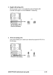
PCI-X slot setting (J15) This jumper allows you to select your desired bus speed for PCI-X1 to enable the onboard Gigabit LAN controller and support 10/100/1000BASE-T networking. PP-DLW PP-DLW PCI Slot Setting J33 1 2 PCI-X 100MHz (Default) 2 3 PCI-X 66MHz ASUS PP-DLW motherboard user guide 2-15 Gigabit LAN setting (J14) Set this jumper to pins 1-2 to PCI-X3 slots. 3. PP-DLW PP-DLW LAN Setting J14 12 23 Enable (Default) Disable 4.
PCI-X slot setting (J15) This jumper allows you to select your desired bus speed for PCI-X1 to enable the onboard Gigabit LAN controller and support 10/100/1000BASE-T networking. PP-DLW PP-DLW PCI Slot Setting J33 1 2 PCI-X 100MHz (Default) 2 3 PCI-X 66MHz ASUS PP-DLW motherboard user guide 2-15 Gigabit LAN setting (J14) Set this jumper to pins 1-2 to PCI-X3 slots. 3. PP-DLW PP-DLW LAN Setting J14 12 23 Enable (Default) Disable 4.
PP-DLW User Manual
Page 42
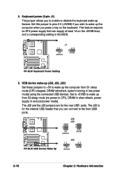
... CPU, DRAM in slow refresh, power supply in low power mode) using the connected USB devices. J28 J29 2 1 +5V (Default) 3 2 +5VSB PP-DLW PP-DLW USB Device Wake Up J20 12 23 +5V (Default) +5VSB 2-16 Chapter 2: Hardware information Set to +5VSB to wake up the computer when you press a key on the +5VSB lead, and a corresponding setting in the BIOS. The J20 is for the rear USB ports. J1 12 23 +5V (Default) +5VSB PP-DLW PP-DLW Keyboard Power Setting 6. Keyboard power (3-pin J1) This jumper...
... CPU, DRAM in slow refresh, power supply in low power mode) using the connected USB devices. J28 J29 2 1 +5V (Default) 3 2 +5VSB PP-DLW PP-DLW USB Device Wake Up J20 12 23 +5V (Default) +5VSB 2-16 Chapter 2: Hardware information Set to +5VSB to wake up the computer when you press a key on the +5VSB lead, and a corresponding setting in the BIOS. The J20 is for the rear USB ports. J1 12 23 +5V (Default) +5VSB PP-DLW PP-DLW Keyboard Power Setting 6. Keyboard power (3-pin J1) This jumper...
PP-DLW User Manual
Page 45
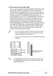
.../66 IDE hard disk ribbon cable. ASUS PP-DLW motherboard user guide 2-19 It is removed to the UltraDMA/100/66 master device. BIOS supports specific device bootup. If you connect the cables. 2. This prevents incorrect orientation when you have more than two UltraDMA/100/66 devices, purchase another for the jumper settings. The hole near the blue connector on the IDE ribbon cable to the secondary IDE connector. For UltraDMA/100/66 IDE devices, use an 80-conductor IDE cable...
.../66 IDE hard disk ribbon cable. ASUS PP-DLW motherboard user guide 2-19 It is removed to the UltraDMA/100/66 master device. BIOS supports specific device bootup. If you connect the cables. 2. This prevents incorrect orientation when you have more than two UltraDMA/100/66 devices, purchase another for the jumper settings. The hole near the blue connector on the IDE ribbon cable to the secondary IDE connector. For UltraDMA/100/66 IDE devices, use an 80-conductor IDE cable...
PP-DLW User Manual
Page 65
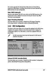
.... For other items, a sub-menu appears when you to display the configuration options. Configuration options: [Disabled] [Primary] [Secondary] [Both] ASUS PP-DLW motherboard user guide 4-7 If an invalid ratio is auto-detected. This item is set in the system. Select an item then press Enter to change the settings for the IDE drives installed in this menu allow you press Enter. Ratio CMOS Setting [8] Sets the ratio between the CPU core clock and the FSB frequency. The values opposite the...
.... For other items, a sub-menu appears when you to display the configuration options. Configuration options: [Disabled] [Primary] [Secondary] [Both] ASUS PP-DLW motherboard user guide 4-7 If an invalid ratio is auto-detected. This item is set in the system. Select an item then press Enter to change the settings for the IDE drives installed in this menu allow you press Enter. Ratio CMOS Setting [8] Sets the ratio between the CPU core clock and the FSB frequency. The values opposite the...
PP-DLW User Manual
Page 66
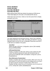
... multiple sectors at a time. Configuration options: [Disabled] [Auto] 4-8 Chapter 4: BIOS Setup These fields display the information of IDE drive. Configuration options: [Disabled] [Auto] Block (Multi-sector Transfer) [Auto] Enables or disables data multi-sectors transfers. Primary IDE Master Primary IDE Slave Secondary IDE Master Secondary IDE Slave While entering Setup, BIOS auto-detects the presence of IDE devices. Select an item then press Enter to Auto enables the LBA mode if the device supports this mode, and if the device was not previously formatted...
... multiple sectors at a time. Configuration options: [Disabled] [Auto] 4-8 Chapter 4: BIOS Setup These fields display the information of IDE drive. Configuration options: [Disabled] [Auto] Block (Multi-sector Transfer) [Auto] Enables or disables data multi-sectors transfers. Primary IDE Master Primary IDE Slave Secondary IDE Master Secondary IDE Slave While entering Setup, BIOS auto-detects the presence of IDE devices. Select an item then press Enter to Auto enables the LBA mode if the device supports this mode, and if the device was not previously formatted...
PP-DLW User Manual
Page 68
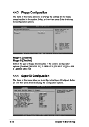
... 3 1/2] [1.44 MB 3 1/2] [2.88 MB 3 1/2] 4.4.4 Super IO Configuration The items in this menu allow you to change the settings for the floppy drives installed in the system. Select an item then press Enter to display the configuration options. 4-10 Chapter 4: BIOS Setup Select an item then press Enter to display the configuration options. 4.4.3 Floppy Configuration The items in this menu allow you to configure the Super I/O chipset. Floppy A [Disabled] Floppy B [Disabled] Selects the type of floppy drive installed in the system.
... 3 1/2] [1.44 MB 3 1/2] [2.88 MB 3 1/2] 4.4.4 Super IO Configuration The items in this menu allow you to change the settings for the floppy drives installed in the system. Select an item then press Enter to display the configuration options. 4-10 Chapter 4: BIOS Setup Select an item then press Enter to display the configuration options. 4.4.3 Floppy Configuration The items in this menu allow you to configure the Super I/O chipset. Floppy A [Disabled] Floppy B [Disabled] Selects the type of floppy drive installed in the system.
PP-DLW User Manual
Page 69
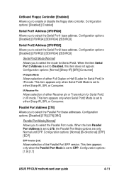
... address. This item appears only when Serial Port2 Mode is set to select the mode for Serial Port2 in IR mode. Configuration options: [1.9] [1.7] ASUS PP-DLW motherboard user guide 4-11 OnBoard Floppy Controller [Enabled] Allows you to Disabled, this item does not appear. Configuration options: [Normal] [Sharp-IR] [SIR] [Consumer] IR Duplex Mode Allows selection of either Receiver pin or Transmit pin for Serial Port2 in IR mode. IR Receiver Pin Allows selection of the Parallel Port EPP version.
... address. This item appears only when Serial Port2 Mode is set to select the mode for Serial Port2 in IR mode. Configuration options: [1.9] [1.7] ASUS PP-DLW motherboard user guide 4-11 OnBoard Floppy Controller [Enabled] Allows you to Disabled, this item does not appear. Configuration options: [Normal] [Sharp-IR] [SIR] [Consumer] IR Duplex Mode Allows selection of either Receiver pin or Transmit pin for Serial Port2 in IR mode. IR Receiver Pin Allows selection of the Parallel Port EPP version.
PP-DLW User Manual
Page 70
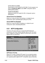
.... Configuration options: [No] [Yes] 4-12 Chapter 4: BIOS Setup ECP Mode DMA Channel [DMA3] Allows selection of the Parallel Port ECP DMA. ACPI Aware O/S [Yes] Allows you to select the Game Port address or to display the configuration options. This item appears only when the Parallel Port Mode is set to enable or disable ACPI support for your operating system. Select an item then press Enter to disable the port. Configuration options: [IRQ5] [IRQ7] Onboard Game Port [Disabled...
.... Configuration options: [No] [Yes] 4-12 Chapter 4: BIOS Setup ECP Mode DMA Channel [DMA3] Allows selection of the Parallel Port ECP DMA. ACPI Aware O/S [Yes] Allows you to select the Game Port address or to display the configuration options. This item appears only when the Parallel Port Mode is set to enable or disable ACPI support for your operating system. Select an item then press Enter to disable the port. Configuration options: [IRQ5] [IRQ7] Onboard Game Port [Disabled...
PP-DLW User Manual
Page 72
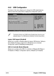
Legacy USB Support [Enabled] Allows you to configure the USB 2.0 controller in this menu allows you to enable or disable support for legacy USB devices. Configuration options: [Disabled] [Enabled] [Auto] USB 2.0 Controller Mode [HiSpeed] Allows you to change the USB-related features. Configuration options: [HiSpeed ] [Full Speed] 4-14 Chapter 4: BIOS Setup The Module Version and USB Devices Enabled items show the autodetected values. Setting to display the configuration options. If no USB devices are connected. Select an item then press Enter to Auto disables the legacy ...
Legacy USB Support [Enabled] Allows you to configure the USB 2.0 controller in this menu allows you to enable or disable support for legacy USB devices. Configuration options: [Disabled] [Enabled] [Auto] USB 2.0 Controller Mode [HiSpeed] Allows you to change the USB-related features. Configuration options: [HiSpeed ] [Full Speed] 4-14 Chapter 4: BIOS Setup The Module Version and USB Devices Enabled items show the autodetected values. Setting to display the configuration options. If no USB devices are connected. Select an item then press Enter to Auto disables the legacy ...
PP-DLW User Manual
Page 91
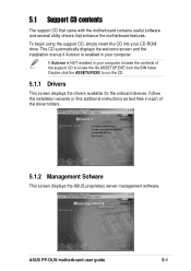
... locate the file ASSETUP.EXE from the BIN folder. ASUS PP-DLW motherboard user guide 5-1 If Autorun is enabled in your computer. Follow the installation wizards or find additional instructions as text files in your CD-ROM drive. The CD automatically displays the welcome screen and the installation menus if Autorun is NOT enabled in each of the support CD to run the CD. 5.1.1 Drivers This screen displays the drivers available for the onboard devices. 5.1 Support...
... locate the file ASSETUP.EXE from the BIN folder. ASUS PP-DLW motherboard user guide 5-1 If Autorun is enabled in your computer. Follow the installation wizards or find additional instructions as text files in your CD-ROM drive. The CD automatically displays the welcome screen and the installation menus if Autorun is NOT enabled in each of the support CD to run the CD. 5.1.1 Drivers This screen displays the drivers available for the onboard devices. 5.1 Support...

PP-DLW User Manual
Page 93
... to install the LAN drivers from the support CD into a floppy disk. ASUS PP-DLW motherboard user guide 5-3 B. Run the dcreat.exe utility from the following screen. 5.2 Microsoft® Windows® NT Server 4.0 5.2.1 Intel® 82540EM LAN driver installation A. Insert the support CD into the floppy disk drive when prompted. 4. Prepare one blank formatted high density floppy disk before proceeding. 1. Preparing the Intel 82540EM LAN Driver Disk Windows NT 4.0 does not have the drivers for the Intel 82540EM LAN controller. Insert the floppy disk...
... to install the LAN drivers from the support CD into a floppy disk. ASUS PP-DLW motherboard user guide 5-3 B. Run the dcreat.exe utility from the following screen. 5.2 Microsoft® Windows® NT Server 4.0 5.2.1 Intel® 82540EM LAN driver installation A. Insert the support CD into the floppy disk drive when prompted. 4. Prepare one blank formatted high density floppy disk before proceeding. 1. Preparing the Intel 82540EM LAN Driver Disk Windows NT 4.0 does not have the drivers for the Intel 82540EM LAN controller. Insert the floppy disk...
PP-DLW User Manual
Page 99
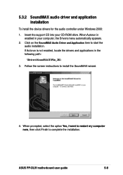
... the option Yes, I want to restart my computer now, then click Finish to start the audio installation. When Autorun in enabled in the following path: \Drivers\SoundMAX\Win_2K\ 3. 5.3.2 SoundMAX audio driver and application installation To install the device drivers for the audio controller under Windows 2000: 1. Follow the screen instructions to install the SoundMAX wizard. 4. If Autorun is not enabled, locate the drivers and applications in your CD-ROM drive. ASUS PP-DLW motherboard user guide 5-9 Insert the support CD...
... the option Yes, I want to restart my computer now, then click Finish to start the audio installation. When Autorun in enabled in the following path: \Drivers\SoundMAX\Win_2K\ 3. 5.3.2 SoundMAX audio driver and application installation To install the device drivers for the audio controller under Windows 2000: 1. Follow the screen instructions to install the SoundMAX wizard. 4. If Autorun is not enabled, locate the drivers and applications in your CD-ROM drive. ASUS PP-DLW motherboard user guide 5-9 Insert the support CD...
PP-DLW User Manual
Page 106
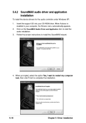
Follow the screen instructions to complete the installation. 5-16 Chapter 5: Driver installation 5.4.2 SoundMAX audio driver and application installation To install the device drivers for the audio controller under Windows XP: 1. When prompted, select the option Yes, I want to restart my computer now, then click Finish to install the SoundMAX wizard. 4. Insert the support CD into your computer, the Drivers menu automatically appears. 2. When Autorun in enabled in your CD-ROM drive. Click on the SoundMAX Audio Driver and Application item to start the audio installation. 3.
Follow the screen instructions to complete the installation. 5-16 Chapter 5: Driver installation 5.4.2 SoundMAX audio driver and application installation To install the device drivers for the audio controller under Windows XP: 1. When prompted, select the option Yes, I want to restart my computer now, then click Finish to install the SoundMAX wizard. 4. Insert the support CD into your computer, the Drivers menu automatically appears. 2. When Autorun in enabled in your CD-ROM drive. Click on the SoundMAX Audio Driver and Application item to start the audio installation. 3.
PP-DLW User Manual
Page 114
... network controller during installation. Also, make the file read-only by itself at : \Drivers\Lan\UNIX\SCO5 Instructions for Installing the eeE Driver for the onboard LAN device. adapters. After the installation of the "Intel ..." By default, the driver automatically detects the line speed and duplex mode. Install the new driver using 'chmod'. Remove all instances of the driver is complete, exit 'custom'. 4. For each adapter that is an older version of these settings...
... network controller during installation. Also, make the file read-only by itself at : \Drivers\Lan\UNIX\SCO5 Instructions for Installing the eeE Driver for the onboard LAN device. adapters. After the installation of the "Intel ..." By default, the driver automatically detects the line speed and duplex mode. Install the new driver using 'chmod'. Remove all instances of the driver is complete, exit 'custom'. 4. For each adapter that is an older version of these settings...
PP-DLW User Manual
Page 115
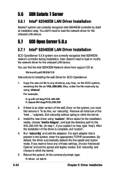
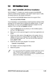
...'. ASUS PP-DLW motherboard user guide 5-25 You can find the driver version by typing 'pkginfo -l eeE'). 4. If you may use the scoadmin Application Installer from the system before installing this package, you require Hot Plug PCI capabilities, the DDI 8 eeE8 driver must be used. 5.8 SCO UnixWare Server 5.8.1 Intel® 82540EM LAN Driver Installation SCO UnixWare 7.1.1 system can find the Intel 82540EM Network driver from support CD at: \Drivers\Lan\UNIX\UW7DDI8 It is supported...
...'. ASUS PP-DLW motherboard user guide 5-25 You can find the driver version by typing 'pkginfo -l eeE'). 4. If you may use the scoadmin Application Installer from the system before installing this package, you require Hot Plug PCI capabilities, the DDI 8 eeE8 driver must be used. 5.8 SCO UnixWare Server 5.8.1 Intel® 82540EM LAN Driver Installation SCO UnixWare 7.1.1 system can find the Intel 82540EM Network driver from support CD at: \Drivers\Lan\UNIX\UW7DDI8 It is supported...


