PP-DLW User Manual
Page 8
... the motherboard and the new technology it supports. • Chapter 2: Hardware information This chapter lists the hardware setup procedures that you need when installing the ASUS PP-DLW motherboard. How this guide This user guide contains the information you have to change system settings through the BIOS Setup menus. It includes description of...
... the motherboard and the new technology it supports. • Chapter 2: Hardware information This chapter lists the hardware setup procedures that you need when installing the ASUS PP-DLW motherboard. How this guide This user guide contains the information you have to change system settings through the BIOS Setup menus. It includes description of...
PP-DLW User Manual
Page 14
Chapter summary 1.1 Welcome 1-1 1.2 Package contents 1-1 1.3 Special features 1-2 1.4 Motherboard overview 1-6 ASUS PP-DLW motherboard
Chapter summary 1.1 Welcome 1-1 1.2 Package contents 1-1 1.3 Special features 1-2 1.4 Motherboard overview 1-6 ASUS PP-DLW motherboard
PP-DLW User Manual
Page 15
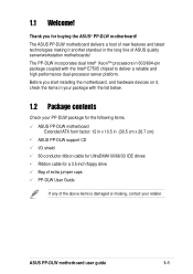
...server platform. 1.1 Welcome! Before you for a 3.5-inch floppy drive Bag of extra jumper caps PP-DLW User Guide If any of ASUS quality server/workstation motherboards! ASUS PP-DLW motherboard user guide 1-1 Thank you start installing the motherboard, and hardware devices on it another standout...PP-DLW package for the following items. ASUS PP-DLW motherboard Extended ATX form factor: 12 in x 10.5 in (30.5 cm x 26.7 cm) ASUS PP-DLW support CD I/O shield 80-conductor ribbon cable for UltraDMA100/66/33 IDE drives Ribbon cable for buying the ASUS® PP-DLW motherboard! The ASUS PP-DLW ...
...server platform. 1.1 Welcome! Before you for a 3.5-inch floppy drive Bag of extra jumper caps PP-DLW User Guide If any of ASUS quality server/workstation motherboards! ASUS PP-DLW motherboard user guide 1-1 Thank you start installing the motherboard, and hardware devices on it another standout...PP-DLW package for the following items. ASUS PP-DLW motherboard Extended ATX form factor: 12 in x 10.5 in (30.5 cm x 26.7 cm) ASUS PP-DLW support CD I/O shield 80-conductor ribbon cable for UltraDMA100/66/33 IDE drives Ribbon cable for buying the ASUS® PP-DLW motherboard! The ASUS PP-DLW ...
PP-DLW User Manual
Page 17
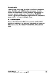
ASUS PP-DLW motherboard user guide 1-3 The CODEC includes analog-to-digital and digital-to-analog sample rate converters, as ATAPI IDE CD-ROM, CD-R/RW, ZIP, and ...
ASUS PP-DLW motherboard user guide 1-3 The CODEC includes analog-to-digital and digital-to-analog sample rate converters, as ATAPI IDE CD-ROM, CD-R/RW, ZIP, and ...

PP-DLW User Manual
Page 19
ASUS PP-DLW motherboard user guide 1-5 Color-coded connectors and descriptive icons make identification easy as required by the PC '99 specification. Compliance Both the BIOS and the hardware levels of the motherboard meet the stringent requirements for Windows NT/2000/XP. The new SDG 2.0 requirements for systems and components are based on the following high-level goals: support for Plug-and-Play compatibility and power management for configuring and managing all system components, 32-bit device drivers, and installation procedures for SDG 2.0 certification.
ASUS PP-DLW motherboard user guide 1-5 Color-coded connectors and descriptive icons make identification easy as required by the PC '99 specification. Compliance Both the BIOS and the hardware levels of the motherboard meet the stringent requirements for Windows NT/2000/XP. The new SDG 2.0 requirements for systems and components are based on the following high-level goals: support for Plug-and-Play compatibility and power management for configuring and managing all system components, 32-bit device drivers, and installation procedures for SDG 2.0 certification.
PP-DLW User Manual
Page 21
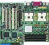
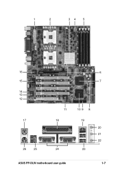
1 2 34 5 16 15 14 13 12 17 26 25 6 7 11 18 24 10 9 8 19 20 21 22 23 ASUS PP-DLW motherboard user guide 1-7
1 2 34 5 16 15 14 13 12 17 26 25 6 7 11 18 24 10 9 8 19 20 21 22 23 ASUS PP-DLW motherboard user guide 1-7
PP-DLW User Manual
Page 23
... 64-bit/133MHz PCI-X slots, three 64-bit/ 100MHz PCI slot, and a 32-bit/33MHz PCI expansion slot support bus master PCI-X/PCI cards. 13 ASUS ASIC. This Mic (pink) port connects a microphone. This Line Out (lime) port connects a headphone or a speaker. 22 Microphone port. This Line In...devices. 19 RJ-45 port. The chipset provides a 32-bit interface and supports 10/100/1000 Mbps data transfer rates. 17 PS/2 mouse port. ASUS PP-DLW motherboard user guide 1-9 The ICH4 communicates with EPP and ECP capabilities, a floppy drive, and PS/2 keyboard and mouse. 16 Intel® 82540EM ...
... 64-bit/133MHz PCI-X slots, three 64-bit/ 100MHz PCI slot, and a 32-bit/33MHz PCI expansion slot support bus master PCI-X/PCI cards. 13 ASUS ASIC. This Mic (pink) port connects a microphone. This Line Out (lime) port connects a headphone or a speaker. 22 Microphone port. This Line In...devices. 19 RJ-45 port. The chipset provides a 32-bit interface and supports 10/100/1000 Mbps data transfer rates. 17 PS/2 mouse port. ASUS PP-DLW motherboard user guide 1-9 The ICH4 communicates with EPP and ECP capabilities, a floppy drive, and PS/2 keyboard and mouse. 16 Intel® 82540EM ...
PP-DLW User Manual
Page 26
Chapter summary 2.1 Motherboard installation 2-1 2.2 Motherboard layout 2-2 2.3 Before you proceed 2-3 2.4 Central Processing Unit (CPU 2-4 2.5 System memory 2-8 2.6 Expansion slots 2-11 2.7 Jumpers 2-14 2.8 Connectors 2-18 ASUS PP-DLW motherboard
Chapter summary 2.1 Motherboard installation 2-1 2.2 Motherboard layout 2-2 2.3 Before you proceed 2-3 2.4 Central Processing Unit (CPU 2-4 2.5 System memory 2-8 2.6 Expansion slots 2-11 2.7 Jumpers 2-14 2.8 Connectors 2-18 ASUS PP-DLW motherboard
PP-DLW User Manual
Page 27
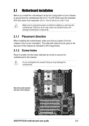
... circles to secure the motherboard to unplug the power cord before installing or removing the motherboard. The PP-DLW uses the extended ATX form factor that you install the motherboard, study the configuration of the chassis ASUS PP-DLW motherboard user guide 2-1 Make sure to the chassis. Doing so may cause you physical injury and...
... circles to secure the motherboard to unplug the power cord before installing or removing the motherboard. The PP-DLW uses the extended ATX form factor that you install the motherboard, study the configuration of the chassis ASUS PP-DLW motherboard user guide 2-1 Make sure to the chassis. Doing so may cause you physical injury and...
PP-DLW User Manual
Page 29
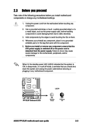
... of the following precautions before removing or plugging in any motherboard component. Whenever you install motherboard components or change any component. 2. PP-DLW PP-DLW Onboard LED LED4 ON Standby Power OFF Powered Off ASUS PP-DLW motherboard user guide 2-3 When lit, the standby power LED (LED4) indicates that the system is detached from the wall socket...
... of the following precautions before removing or plugging in any motherboard component. Whenever you install motherboard components or change any component. 2. PP-DLW PP-DLW Onboard LED LED4 ON Standby Power OFF Powered Off ASUS PP-DLW motherboard user guide 2-3 When lit, the standby power LED (LED4) indicates that the system is detached from the wall socket...
PP-DLW User Manual
Page 31
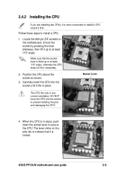
... socket by pressing the lever sideways, then lift it up to at least 115° angle. Follow these steps to install in CPU socket 2 first. ASUS PP-DLW motherboard user guide 2-5 2.4.2 Installing the CPU If you are installing two CPUs, it is lifted up to at least 115° angle, otherwise the CPU...
... socket by pressing the lever sideways, then lift it up to at least 115° angle. Follow these steps to install in CPU socket 2 first. ASUS PP-DLW motherboard user guide 2-5 2.4.2 Installing the CPU If you are installing two CPUs, it is lifted up to at least 115° angle, otherwise the CPU...
PP-DLW User Manual
Page 33
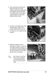
... FAN2 (for the CPU on socket 1) and FAN3 (for the CPU on socket 2). Hardware monitoring problems may occur if you properly attached the two ends. 5. 3. ASUS PP-DLW motherboard user guide 2-7 The middle hook of the bracket snaps in place if you properly attached the two ends. 4.
... FAN2 (for the CPU on socket 1) and FAN3 (for the CPU on socket 2). Hardware monitoring problems may occur if you properly attached the two ends. 5. 3. ASUS PP-DLW motherboard user guide 2-7 The middle hook of the bracket snaps in place if you properly attached the two ends. 4.

PP-DLW User Manual
Page 35
... A Module A Module B Table 2 Memory frequency/CPU FSB synchronization CPU FSB 533 MHz 400 MHz DDR DIMM Type PC2100 PC1600 Memory Frequency 266 MHz 200 MHz ASUS PP-DLW motherboard user guide 2-9 Install only identical (the same type and size) DDR DIMM pairs using the memory configurations presented in any configuration. Make sure that...
... A Module A Module B Table 2 Memory frequency/CPU FSB synchronization CPU FSB 533 MHz 400 MHz DDR DIMM Type PC2100 PC1600 Memory Frequency 266 MHz 200 MHz ASUS PP-DLW motherboard user guide 2-9 Install only identical (the same type and size) DDR DIMM pairs using the memory configurations presented in any configuration. Make sure that...
PP-DLW User Manual
Page 37
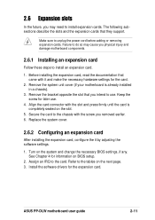
.... 2. Replace the system cover. 2.6.2 Configuring an expansion card After installing the expansion card, configure the it and make the necessary hardware settings for later use . ASUS PP-DLW motherboard user guide 2-11 See Chapter 4 for the expansion card. Remove the bracket opposite the slot that you may cause you removed earlier. 6. Refer to...
.... 2. Replace the system cover. 2.6.2 Configuring an expansion card After installing the expansion card, configure the it and make the necessary hardware settings for later use . ASUS PP-DLW motherboard user guide 2-11 See Chapter 4 for the expansion card. Remove the bracket opposite the slot that you may cause you removed earlier. 6. Refer to...
PP-DLW User Manual
Page 39
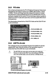
PCI-X is primarily designed for 1.5V PP-DLW PP-DLW Accelerated Graphics Port (AGP) ASUS PP-DLW motherboard user guide 2-13 PCI-X1 (66/100MHz, 3.3V) PCI-X2 (66/100MHz, 3.3V) PCI-X3 (66/100MHz, 3.3V) PCI-X4 (133MHz, 3.3V) PCI 1 (33MHz, ...
PCI-X is primarily designed for 1.5V PP-DLW PP-DLW Accelerated Graphics Port (AGP) ASUS PP-DLW motherboard user guide 2-13 PCI-X1 (66/100MHz, 3.3V) PCI-X2 (66/100MHz, 3.3V) PCI-X3 (66/100MHz, 3.3V) PCI-X4 (133MHz, 3.3V) PCI 1 (33MHz, ...
PP-DLW User Manual
Page 41
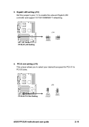
PP-DLW PP-DLW PCI Slot Setting J33 1 2 PCI-X 100MHz (Default) 2 3 PCI-X 66MHz ASUS PP-DLW motherboard user guide 2-15 PCI-X slot setting (J15) This jumper allows you to select your desired bus speed for PCI-X1 to enable the onboard Gigabit LAN controller and support 10/100/1000BASE-T networking. Gigabit LAN setting (J14) Set this jumper to pins 1-2 to PCI-X3 slots. 3. PP-DLW PP-DLW LAN Setting J14 12 23 Enable (Default) Disable 4.
PP-DLW PP-DLW PCI Slot Setting J33 1 2 PCI-X 100MHz (Default) 2 3 PCI-X 66MHz ASUS PP-DLW motherboard user guide 2-15 PCI-X slot setting (J15) This jumper allows you to select your desired bus speed for PCI-X1 to enable the onboard Gigabit LAN controller and support 10/100/1000BASE-T networking. Gigabit LAN setting (J14) Set this jumper to pins 1-2 to PCI-X3 slots. 3. PP-DLW PP-DLW LAN Setting J14 12 23 Enable (Default) Disable 4.
PP-DLW User Manual
Page 43
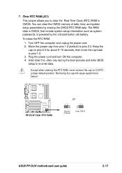
... the computer and unplug the power cord. 2. Keep the cap on CLRTC jumper default position. The RAM data in CMOS. PP-DLW PP-DLW Clear RTC RAM J21 12 23 Normal (Default) Clear CMOS ASUS PP-DLW motherboard user guide 2-17 To erase the RTC RAM: 1. Move the jumper cap from pins 1-2 (default) to pins 1-2. 3. Plug the...
... the computer and unplug the power cord. 2. Keep the cap on CLRTC jumper default position. The RAM data in CMOS. PP-DLW PP-DLW Clear RTC RAM J21 12 23 Normal (Default) Clear CMOS ASUS PP-DLW motherboard user guide 2-17 To erase the RTC RAM: 1. Move the jumper cap from pins 1-2 (default) to pins 1-2. 3. Plug the...
PP-DLW User Manual
Page 45
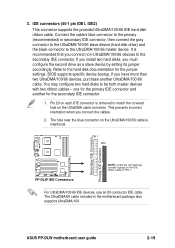
...: Orient the red markings (usually zigzag) on each IDE connector is intentional. The UltraDMA/66 cable included in the motherboard package also supports UltraDMA/100. 3. ASUS PP-DLW motherboard user guide 2-19 Connect the cable's blue connector to the primary (recommended) or secondary IDE connector, then connect the gray connector to the UltraDMA...
...: Orient the red markings (usually zigzag) on each IDE connector is intentional. The UltraDMA/66 cable included in the motherboard package also supports UltraDMA/100. 3. ASUS PP-DLW motherboard user guide 2-19 Connect the cable's blue connector to the primary (recommended) or secondary IDE connector, then connect the gray connector to the UltraDMA...
PP-DLW User Manual
Page 47
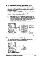
... connectors in only one orientation. The plugs from the power supply are designed to an ATX 12V power supply. PP-DLW PP-DLW Intel Panel Connector J5 BOUT_L BOUT_R +5VA AGND_A LOUT_L NC LOUT_R MICPWR MIC2 1 ASUS PP-DLW motherboard user guide 2-21 The minimum recommended wattage is inadequate. 24-pin Power Connector 1 +3 Volts +3 Volts +3 Volts -12...
... connectors in only one orientation. The plugs from the power supply are designed to an ATX 12V power supply. PP-DLW PP-DLW Intel Panel Connector J5 BOUT_L BOUT_R +5VA AGND_A LOUT_L NC LOUT_R MICPWR MIC2 1 ASUS PP-DLW motherboard user guide 2-21 The minimum recommended wattage is inadequate. 24-pin Power Connector 1 +3 Volts +3 Volts +3 Volts -12...
PP-DLW User Manual
Page 49
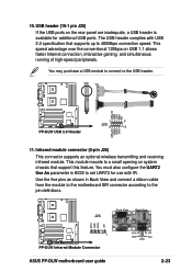
...) This connector supports an optional wireless transmitting and receiving infrared module. J26 Front View Back View IRTX GND IRRX +5V 1 PP-DLW PP-DLW Infrared Module Connector ASUS PP-DLW motherboard user guide IRTX GND IRRX +5V (NC) 2-23 You may purchase a USB module to connect to the pin definitions.... The USB header complies with IR. USB+5V LDM1 LDP1 GND NC PP-DLW PP-DLW USB 2.0 Header 1 5 J25 6 10 USB+5V LDM2 LDP2 GND...
...) This connector supports an optional wireless transmitting and receiving infrared module. J26 Front View Back View IRTX GND IRRX +5V 1 PP-DLW PP-DLW Infrared Module Connector ASUS PP-DLW motherboard user guide IRTX GND IRRX +5V (NC) 2-23 You may purchase a USB module to connect to the pin definitions.... The USB header complies with IR. USB+5V LDM1 LDP1 GND NC PP-DLW PP-DLW USB 2.0 Header 1 5 J25 6 10 USB+5V LDM2 LDP2 GND...


