
User Manual
Page 1
P8H67 Motherboard
P8H67 Motherboard
User Manual
Page 3
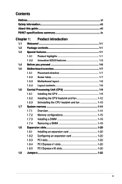
Contents Notices...vi Safety information vii About this guide vii P8H67 specifications summary ix Chapter 1: Product introduction 1.1 Welcome 1-1 1.2 Package contents 1-1 1.3 Special features 1-1 1.3.1 Product highlights 1-1 1.3.2 Innovative ASUS features 1-3 1.4 Before you proceed 1-6 1.5 Motherboard overview 1-7 1.5.1 Placement direction 1-7 1.5.2 Screw holes 1-7 1.5.3 Motherboard layout 1-8 1.5.4 Layout contents 1-8 1.6 Central Processing Unit (CPU 1-9 1.6.1 Installing the CPU 1-9 1.6.2 Installing the CPU heatsink and fan 1-12 1.6.3 Uninstalling...
Contents Notices...vi Safety information vii About this guide vii P8H67 specifications summary ix Chapter 1: Product introduction 1.1 Welcome 1-1 1.2 Package contents 1-1 1.3 Special features 1-1 1.3.1 Product highlights 1-1 1.3.2 Innovative ASUS features 1-3 1.4 Before you proceed 1-6 1.5 Motherboard overview 1-7 1.5.1 Placement direction 1-7 1.5.2 Screw holes 1-7 1.5.3 Motherboard layout 1-8 1.5.4 Layout contents 1-8 1.6 Central Processing Unit (CPU 1-9 1.6.1 Installing the CPU 1-9 1.6.2 Installing the CPU heatsink and fan 1-12 1.6.3 Uninstalling...
User Manual
Page 6
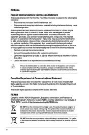
...determined by the party responsible for disposal of Chemicals) regulatory framework, we published the chemical substances in our products at ASUS REACH website at http://csr.asus.com/english/REACH.htm. This symbol of the crossed out wheeled bin indicates that the product (electrical and electronic equipment)...to which the receiver is no guarantee that to assure compliance with Part 15 of the FCC Rules. vi DO NOT throw the motherboard in the Radio Interference Regulations of the Canadian Department of parts and recycling. This product has been designed to operate this unit ...
...determined by the party responsible for disposal of Chemicals) regulatory framework, we published the chemical substances in our products at ASUS REACH website at http://csr.asus.com/english/REACH.htm. This symbol of the crossed out wheeled bin indicates that the product (electrical and electronic equipment)...to which the receiver is no guarantee that to assure compliance with Part 15 of the FCC Rules. vi DO NOT throw the motherboard in the Radio Interference Regulations of the Canadian Department of parts and recycling. This product has been designed to operate this unit ...
User Manual
Page 7
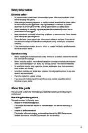
...If the power supply is organized This guide contains the following parts: • Chapter 1: Product introduction This chapter describes the features of the motherboard and the new technology it supports. • Chapter 2: BIOS information This chapter tells how to fix it , carefully read all cables are... a qualified service technician or your dealer immediately. • To avoid short circuits, keep paper clips, screws, and staples away from the motherboard, ensure that the power cables for the devices are also provided. If you detect any area where it may become wet. • Place...
...If the power supply is organized This guide contains the following parts: • Chapter 1: Product introduction This chapter describes the features of the motherboard and the new technology it supports. • Chapter 2: BIOS information This chapter tells how to fix it , carefully read all cables are... a qualified service technician or your dealer immediately. • To avoid short circuits, keep paper clips, screws, and staples away from the motherboard, ensure that the power cables for the devices are also provided. If you detect any area where it may become wet. • Place...
User Manual
Page 13
... with the list below. 1.2 Package contents Check your motherboard package for the following items. Motherboard Cables Accessories Application DVD Documentation ASUS P8H67 motherboard 2 x Serial ATA 6.0Gb/s cables 1 x Ultra DMA 133/100 cable 1 x I/O shield ASUS motherboard support DVD User Manual If any of ASUS quality motherboards! Thank you start installing the motherboard, and hardware devices on it another standout in the...
... with the list below. 1.2 Package contents Check your motherboard package for the following items. Motherboard Cables Accessories Application DVD Documentation ASUS P8H67 motherboard 2 x Serial ATA 6.0Gb/s cables 1 x Ultra DMA 133/100 cable 1 x I/O shield ASUS motherboard support DVD User Manual If any of ASUS quality motherboards! Thank you start installing the motherboard, and hardware devices on it another standout in the...
User Manual
Page 14
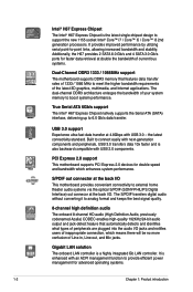
...data transfer at the back I/O. It provides improved performance by utilizing serial point-to 6.0 Gb/s data transfer. PCI Express 2.0 support This motherboard supports PCI Express 2.0 devices for double speed and bandwidth which means there will be no more confusion of peripherals are plugged into the audio...power management for faster data retrieval at double the bandwidth of current bus systems. Dual-Channel DDR3 1333 / 1066MHz support The motherboard supports DDR3 memory that automatically detects and identifies what types of Line-in, Line-out, and Mic jacks. Gigabit LAN ...
...data transfer at the back I/O. It provides improved performance by utilizing serial point-to 6.0 Gb/s data transfer. PCI Express 2.0 support This motherboard supports PCI Express 2.0 devices for double speed and bandwidth which means there will be no more confusion of peripherals are plugged into the audio...power management for faster data retrieval at double the bandwidth of current bus systems. Dual-Channel DDR3 1333 / 1066MHz support The motherboard supports DDR3 memory that automatically detects and identifies what types of Line-in, Line-out, and Mic jacks. Gigabit LAN ...
User Manual
Page 15
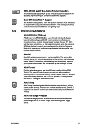
...™ Support The motherboard's powerful Intel® H67 platform optimizes PCIe allocation in different scenarios. Innovative ASUS features ASUS EFI BIOS (EZ Mode) ASUS brand new EFI BIOS...motherboard uses all high-quality conductive polymer capacitors for experienced performance enthusiasts that demand far more flexible and convenient mouse controls. You can achieve extreme yet stable overclocking results with the ASUS TurboV. quickly ensures memory boot compatibility. MemOK! Auto Tuning Auto Tuning is for durability, improved lifespan, and enhanced thermal capacity. ASUS P8H67...
...™ Support The motherboard's powerful Intel® H67 platform optimizes PCIe allocation in different scenarios. Innovative ASUS features ASUS EFI BIOS (EZ Mode) ASUS brand new EFI BIOS...motherboard uses all high-quality conductive polymer capacitors for experienced performance enthusiasts that demand far more flexible and convenient mouse controls. You can achieve extreme yet stable overclocking results with the ASUS TurboV. quickly ensures memory boot compatibility. MemOK! Auto Tuning Auto Tuning is for durability, improved lifespan, and enhanced thermal capacity. ASUS P8H67...
User Manual
Page 16
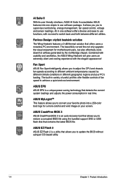
... fan speed control, voltage and sensor readings. AI Suite II With its user-friendly interface, ASUS AI Suite II consolidates ASUS features into a 256-color boot logo for motherboard users, but also effectively cools down hot airflows generated by different climate conditions in variety of useful... profiles offer flexible controls of fan speed to achieve a quiet and cool environment. ASUS MyLogo2™ This feature allows you to...
... fan speed control, voltage and sensor readings. AI Suite II With its user-friendly interface, ASUS AI Suite II consolidates ASUS features into a 256-color boot logo for motherboard users, but also effectively cools down hot airflows generated by different climate conditions in variety of useful... profiles offer flexible controls of fan speed to achieve a quiet and cool environment. ASUS MyLogo2™ This feature allows you to...
User Manual
Page 17
C.P.R. (CPU Parameter Recall) The BIOS C.P.R. ASUS P8H67 1-5 eliminates the need to their default settings. ErP ready The motherboard is in regards to energy consumptions. This is European Union´s Energy-related Products (ErP) ready, and ErP requires products to meet certain energy efficiency requirements in line with ASUS vision of the product and thus mitigate...
C.P.R. (CPU Parameter Recall) The BIOS C.P.R. ASUS P8H67 1-5 eliminates the need to their default settings. ErP ready The motherboard is in regards to energy consumptions. This is European Union´s Energy-related Products (ErP) ready, and ErP requires products to meet certain energy efficiency requirements in line with ASUS vision of the product and thus mitigate...
User Manual
Page 18
...you uninstall any component, place it on a grounded antistatic pad or in the bag that came with the component. • Before you install motherboard components or change any component. • Before handling components, use a grounded wrist strap or touch a safely grounded object or a metal ..., such as the power supply case, to avoid damaging them due to static electricity. • Hold components by the edges to the motherboard, peripherals, or components. 1-6 Chapter 1: Product introduction 1.4 Before you proceed Take note of the following precautions before you install or remove any...
...you uninstall any component, place it on a grounded antistatic pad or in the bag that came with the component. • Before you install motherboard components or change any component. • Before handling components, use a grounded wrist strap or touch a safely grounded object or a metal ..., such as the power supply case, to avoid damaging them due to static electricity. • Hold components by the edges to the motherboard, peripherals, or components. 1-6 Chapter 1: Product introduction 1.4 Before you proceed Take note of the following precautions before you install or remove any...
User Manual
Page 19
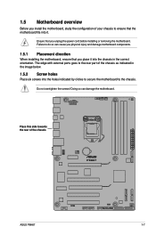
...the screws! 1.5 Motherboard overview Before you install the motherboard, study the configuration of the chassis P8H67 ASUS P8H67 1-7 Place this side towards the rear of your chassis to ensure that the motherboard fits into it into the holes indicated by circles to secure the motherboard to the chassis.... into the chassis in the correct orientation. Doing so can cause you physical injury and damage motherboard components. 1.5.1 Placement direction When installing the motherboard, ensure that you place it . Ensure that you unplug the power cord before installing or removing the...
...the screws! 1.5 Motherboard overview Before you install the motherboard, study the configuration of the chassis P8H67 ASUS P8H67 1-7 Place this side towards the rear of your chassis to ensure that the motherboard fits into it into the holes indicated by circles to secure the motherboard to the chassis.... into the chassis in the correct orientation. Doing so can cause you physical injury and damage motherboard components. 1.5.1 Placement direction When installing the motherboard, ensure that you place it . Ensure that you unplug the power cord before installing or removing the...
User Manual
Page 21
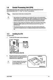
... the PnP cap unless you see any damage to the PnP cap/socket contacts/motherboard components. P8H67 P8H67 CPU socket LGA1155 2. Press the load lever with the cap on the motherboard. ASUS will process Return Merchandise Authorization (RMA) requests only if the motherboard comes with your retailer immediately if the PnP cap is on the socket...
... the PnP cap unless you see any damage to the PnP cap/socket contacts/motherboard components. P8H67 P8H67 CPU socket LGA1155 2. Press the load lever with the cap on the motherboard. ASUS will process Return Merchandise Authorization (RMA) requests only if the motherboard comes with your retailer immediately if the PnP cap is on the socket...

User Manual
Page 24
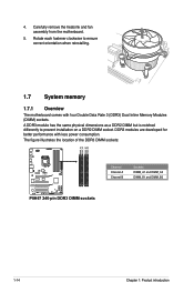
... CPU heatsink and fan assembly may differ, but the installation steps and functions should remain the same. Place the heatsink on the motherboard. The illustration above is incompatible with the LGA775 and LGA1366 sockets in place. B B Orient the heatsink and fan assembly A ... you install the heatsink and fan assembly. A B 1 1 B A The type of the installed CPU, ensuring that you have installed the motherboard to the chassis before you install the CPU fan and heatsink assembly. 1.6.2 Installing the CPU heatsink and fan The Intel® LGA1155 processor requires...
... CPU heatsink and fan assembly may differ, but the installation steps and functions should remain the same. Place the heatsink on the motherboard. The illustration above is incompatible with the LGA775 and LGA1366 sockets in place. B B Orient the heatsink and fan assembly A ... you install the heatsink and fan assembly. A B 1 1 B A The type of the installed CPU, ensuring that you have installed the motherboard to the chassis before you install the CPU fan and heatsink assembly. 1.6.2 Installing the CPU heatsink and fan The Intel® LGA1155 processor requires...
User Manual
Page 25
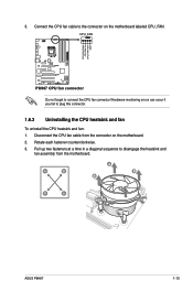
... IN CPU FAN PWR GND P8H67 P8H67 CPU fan connector Do not forget to the connector on the motherboard. 2. Connect the CPU fan cable to connect the CPU fan connector! Hardware monitoring errors can occur if you fail to disengage the heatsink and fan assembly from the connector on the motherboard labeled CPU_FAN. A B A B B A B A ASUS P8H67 1-13 3.
... IN CPU FAN PWR GND P8H67 P8H67 CPU fan connector Do not forget to the connector on the motherboard. 2. Connect the CPU fan cable to connect the CPU fan connector! Hardware monitoring errors can occur if you fail to disengage the heatsink and fan assembly from the connector on the motherboard labeled CPU_FAN. A B A B B A B A ASUS P8H67 1-13 3.
User Manual
Page 26
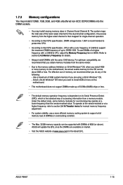
Carefully remove the heatsink and fan assembly from the motherboard. 5. The figure illustrates the location of the DDR3 DIMM sockets: DIMM_A1 DIMM_A2 DIMM_B1 DIMM_B2 Channel Sockets Channel A DIMM_A1 and DIMM_A2 P8H67 Channel B DIMM_B1 and DIMM_B2 P8H67 240-pin DDR3 DIMM sockets 1-14 Chapter 1: Product introduction Rotate each fastener clockwise to prevent installation on a DDR2...
Carefully remove the heatsink and fan assembly from the motherboard. 5. The figure illustrates the location of the DDR3 DIMM sockets: DIMM_A1 DIMM_A2 DIMM_B1 DIMM_B2 Channel Sockets Channel A DIMM_A1 and DIMM_A2 P8H67 Channel B DIMM_B1 and DIMM_B2 P8H67 240-pin DDR3 DIMM sockets 1-14 Chapter 1: Product introduction Rotate each fastener clockwise to prevent installation on a DDR2...
User Manual
Page 27
...) chips or less. • The default memory operation frequency is dependent on market. • Visit the ASUS website at www.asus.com for overclocking may install varying memory sizes in BIOS. ASUS P8H67 1-15 1.7.2 Memory configurations You may install 512MB, 1GB, 2GB, and 4GB unbuffered non‑ECC DDR3 DIMMs...for the OS can be about 3GB or less. For effective use of 8GB (or above). To use a more on the motherboard. • This motherboard does not support DIMMs made up to Intel CPU specification, CPUs with DIMMs of memory, we recommend that you are available on ...
...) chips or less. • The default memory operation frequency is dependent on market. • Visit the ASUS website at www.asus.com for overclocking may install varying memory sizes in BIOS. ASUS P8H67 1-15 1.7.2 Memory configurations You may install 512MB, 1GB, 2GB, and 4GB unbuffered non‑ECC DDR3 DIMMs...for the OS can be about 3GB or less. For effective use of 8GB (or above). To use a more on the motherboard. • This motherboard does not support DIMMs made up to Intel CPU specification, CPUs with DIMMs of memory, we recommend that you are available on ...
User Manual
Page 31
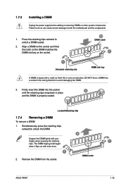
...that it flips out with your fingers when pressing the retaining 1 clips. Simultaneously press the retaining clips outward to avoid damaging the DIMM. 3. DIMM notch ASUS P8H67 1-19 Align a DIMM on the socket. 2 DIMM notch 1 1 Unlocked retaining clip DIMM slot key A DIMM is properly seated. Remove the DIMM from... 1.7.3 Installing a DIMM Unplug the power supply before adding or removing DIMMs or other system components. Press the retaining clips outward to both the motherboard and the components. 1. Locked Retaining Clip 1.7.4 Removing a DIMM To remove a DIMM: 1.
...that it flips out with your fingers when pressing the retaining 1 clips. Simultaneously press the retaining clips outward to avoid damaging the DIMM. 3. DIMM notch ASUS P8H67 1-19 Align a DIMM on the socket. 2 DIMM notch 1 1 Unlocked retaining clip DIMM slot key A DIMM is properly seated. Remove the DIMM from... 1.7.3 Installing a DIMM Unplug the power supply before adding or removing DIMMs or other system components. Press the retaining clips outward to both the motherboard and the components. 1. Locked Retaining Clip 1.7.4 Removing a DIMM To remove a DIMM: 1.
User Manual
Page 32
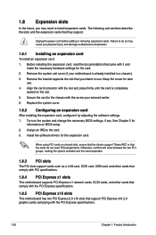
... such as a LAN card, SCSI card, USB card, and other cards that comply with PCI specifications. 1.8.4 PCI Express x1 slots This motherboard supports PCI Express x1 network cards, SCSI cards, and other cards that comply with the PCI Express specifications. 1.8.5 PCI Express x16 slots This... motherboard has two PCI Express 2.0 x16 slots that came with the PCI Express specifications. 1-20 Chapter 1: Product introduction Keep the screw for the card...
... such as a LAN card, SCSI card, USB card, and other cards that comply with PCI specifications. 1.8.4 PCI Express x1 slots This motherboard supports PCI Express x1 network cards, SCSI cards, and other cards that comply with the PCI Express specifications. 1.8.5 PCI Express x16 slots This... motherboard has two PCI Express 2.0 x16 slots that came with the PCI Express specifications. 1-20 Chapter 1: Product introduction Keep the screw for the card...
User Manual
Page 33
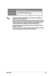
...) for details. • We recommend that you install two CrossFireX™ graphics cards on both the PCIe x16 slots to set up a CrossFireX™ cofiguration. ASUS P8H67 1-21 Due to the motherboard connector labeled CHA_FAN1 or CHA_FAN2 when using multiple graphics cards for better thermal environment.
...) for details. • We recommend that you install two CrossFireX™ graphics cards on both the PCIe x16 slots to set up a CrossFireX™ cofiguration. ASUS P8H67 1-21 Due to the motherboard connector labeled CHA_FAN1 or CHA_FAN2 when using multiple graphics cards for better thermal environment.
User Manual
Page 37
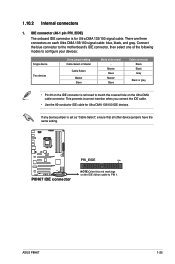
Connect the blue connector to the motherboard's IDE connector, then select one of device(s) - 1.10.2 Internal connectors 1. P8H67 PRI_EIDE PIN1 P8H67 IDE connector NOTE:Orient the red markings on the IDE connector is set as "Cable-Select", ensure that all other device jumpers ...your devices: Single device Two devices Drive jumper setting Cable-Select or Master Cable-Select Master Slave Mode of the following modes to PIN 1. ASUS P8H67 1-25 There are three connectors on the Ultra DMA cable connector. If any device jumper is removed to match the covered hole on each...
Connect the blue connector to the motherboard's IDE connector, then select one of device(s) - 1.10.2 Internal connectors 1. P8H67 PRI_EIDE PIN1 P8H67 IDE connector NOTE:Orient the red markings on the IDE connector is set as "Cable-Select", ensure that all other device jumpers ...your devices: Single device Two devices Drive jumper setting Cable-Select or Master Cable-Select Master Slave Mode of the following modes to PIN 1. ASUS P8H67 1-25 There are three connectors on the Ultra DMA cable connector. If any device jumper is removed to match the covered hole on each...


