
User Manual
Page 1
P8H67 Motherboard
P8H67 Motherboard
User Manual
Page 3
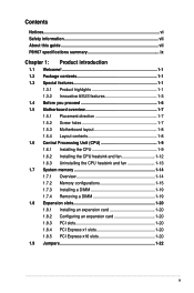
Contents Notices...vi Safety information vii About this guide vii P8H67 specifications summary ix Chapter 1: Product introduction 1.1 Welcome 1-1 1.2 Package contents 1-1 1.3 Special features 1-1 1.3.1 Product highlights 1-1 1.3.2 Innovative ASUS features 1-3 1.4 Before you proceed 1-6 1.5 Motherboard overview 1-7 1.5.1 Placement direction 1-7 1.5.2 Screw holes 1-7 1.5.3 Motherboard layout 1-8 1.5.4 Layout contents 1-8 1.6 Central Processing Unit (CPU 1-9 1.6.1 Installing the CPU 1-9 1.6.2 Installing the CPU heatsink and fan 1-12 1.6.3 Uninstalling...
Contents Notices...vi Safety information vii About this guide vii P8H67 specifications summary ix Chapter 1: Product introduction 1.1 Welcome 1-1 1.2 Package contents 1-1 1.3 Special features 1-1 1.3.1 Product highlights 1-1 1.3.2 Innovative ASUS features 1-3 1.4 Before you proceed 1-6 1.5 Motherboard overview 1-7 1.5.1 Placement direction 1-7 1.5.2 Screw holes 1-7 1.5.3 Motherboard layout 1-8 1.5.4 Layout contents 1-8 1.6 Central Processing Unit (CPU 1-9 1.6.1 Installing the CPU 1-9 1.6.2 Installing the CPU heatsink and fan 1-12 1.6.3 Uninstalling...
User Manual
Page 6
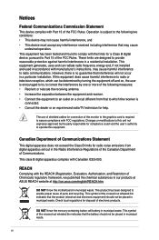
...graphics card is no guarantee that the product (electrical and electronic equipment) should not be placed in a particular installation. DO NOT throw the motherboard in municipal waste. Check local regulations for connection of the crossed out wheeled bin indicates that interference will not occur in municipal waste. Notices Federal..., and • This device must accept any interference received including interference that the battery should not be placed in our products at ASUS REACH website at http://csr.asus.com/english/REACH.htm. This symbol of the FCC Rules.
...graphics card is no guarantee that the product (electrical and electronic equipment) should not be placed in a particular installation. DO NOT throw the motherboard in municipal waste. Check local regulations for connection of the crossed out wheeled bin indicates that interference will not occur in municipal waste. Notices Federal..., and • This device must accept any interference received including interference that the battery should not be placed in our products at ASUS REACH website at http://csr.asus.com/english/REACH.htm. This symbol of the FCC Rules.
User Manual
Page 7
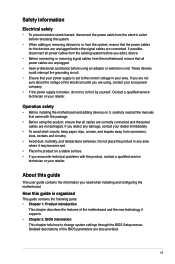
... and the power cables are also provided. How this guide This user guide contains the information you need when installing and configuring the motherboard. If you are unplugged. • Seek professional assistance before using , contact your local power company. • If the power supply...surface. • If you add a device. • Before connecting or removing signal cables from the motherboard, ensure that all power cables are not sure about the voltage of the motherboard and the new technology it supports. • Chapter 2: BIOS information This chapter tells how to fix it...
... and the power cables are also provided. How this guide This user guide contains the information you need when installing and configuring the motherboard. If you are unplugged. • Seek professional assistance before using , contact your local power company. • If the power supply...surface. • If you add a device. • Before connecting or removing signal cables from the motherboard, ensure that all power cables are not sure about the voltage of the motherboard and the new technology it supports. • Chapter 2: BIOS information This chapter tells how to fix it...
User Manual
Page 13
... in LGA1155 package with the list below. 1.2 Package contents Check your motherboard package for the following items. Motherboard Cables Accessories Application DVD Documentation ASUS P8H67 motherboard 2 x Serial ATA 6.0Gb/s cables 1 x Ultra DMA 133/100 cable 1 x I/O shield ASUS motherboard support DVD User Manual If any of ASUS quality motherboards! Intel® Second Generation Core™ i7/ Core™ i5/ Core...
... in LGA1155 package with the list below. 1.2 Package contents Check your motherboard package for the following items. Motherboard Cables Accessories Application DVD Documentation ASUS P8H67 motherboard 2 x Serial ATA 6.0Gb/s cables 1 x Ultra DMA 133/100 cable 1 x I/O shield ASUS motherboard support DVD User Manual If any of ASUS quality motherboards! Intel® Second Generation Core™ i7/ Core™ i5/ Core...
User Manual
Page 14
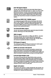
...; i7 / Core™ i5 / Core™ i3 2nd generation processors. the latest connectivity standard. PCI Express 2.0 support This motherboard supports PCI Express 2.0 devices for double speed and bandwidth which means there will be no more confusion of inappropriate connection, which enhances... applications. It is enhanced with USB 2.0 components. USB 3.0 support Experience ultra-fast data transfer at the back I /O This motherboard provides convenient connectivity to meet the higher bandwidth requirements of 1333 / 1066 MHz to external home theater audio systems via the optical ...
...; i7 / Core™ i5 / Core™ i3 2nd generation processors. the latest connectivity standard. PCI Express 2.0 support This motherboard supports PCI Express 2.0 devices for double speed and bandwidth which means there will be no more confusion of inappropriate connection, which enhances... applications. It is enhanced with USB 2.0 components. USB 3.0 support Experience ultra-fast data transfer at the back I /O This motherboard provides convenient connectivity to meet the higher bandwidth requirements of 1333 / 1066 MHz to external home theater audio systems via the optical ...
User Manual
Page 15
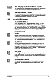
... Auto Tuning Auto Tuning is for durability, improved lifespan, and enhanced thermal capacity. ASUS Anti-Surge Protection This special design prevents expensive devices and the motherboard from damage caused by power surges from switching power supply (PSU). Quad-GPU CrossFireX&#... Polymer Capacitors This motherboard uses all high-quality conductive polymer capacitors for experienced performance enthusiasts that demand far more flexible and convenient mouse controls. beginners can easily navigate the new EFI BIOS with just a few clicks away. ASUS P8H67 1-3 This allows ...
... Auto Tuning Auto Tuning is for durability, improved lifespan, and enhanced thermal capacity. ASUS Anti-Surge Protection This special design prevents expensive devices and the motherboard from damage caused by power surges from switching power supply (PSU). Quad-GPU CrossFireX&#... Polymer Capacitors This motherboard uses all high-quality conductive polymer capacitors for experienced performance enthusiasts that demand far more flexible and convenient mouse controls. beginners can easily navigate the new EFI BIOS with just a few clicks away. ASUS P8H67 1-3 This allows ...
User Manual
Page 16
... DVD or USB flash disk that offers users a noiseless PC environment. AI Suite II With its user-friendly interface, ASUS AI Suite II consolidates ASUS features into a 256-color boot logo for motherboard users, but also effectively cools down hot airflows generated by different climate conditions in variety of useful profiles offer flexible...
... DVD or USB flash disk that offers users a noiseless PC environment. AI Suite II With its user-friendly interface, ASUS AI Suite II consolidates ASUS features into a 256-color boot logo for motherboard users, but also effectively cools down hot airflows generated by different climate conditions in variety of useful profiles offer flexible...
User Manual
Page 17
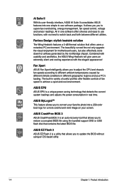
... ready The motherboard is in regards to energy consumptions. This is European Union´s Energy-related Products (ErP) ready, and ErP requires products to meet certain energy efficiency requirements in line with ASUS vision of creating environment-friendly and energy-efficient products through product design and innovation to their default settings. ASUS P8H67 1-5 C.P.R. (CPU...
... ready The motherboard is in regards to energy consumptions. This is European Union´s Energy-related Products (ErP) ready, and ErP requires products to meet certain energy efficiency requirements in line with ASUS vision of creating environment-friendly and energy-efficient products through product design and innovation to their default settings. ASUS P8H67 1-5 C.P.R. (CPU...
User Manual
Page 18
... you uninstall any component, place it on a grounded antistatic pad or in the bag that came with the component. • Before you install motherboard components or change any motherboard settings. • Unplug the power cord from the wall socket before touching any component, ensure that the ATX power supply is switched off... or a metal object, such as the power supply case, to avoid damaging them due to static electricity. • Hold components by the edges to the motherboard, peripherals, or components. 1-6 Chapter 1: Product introduction
... you uninstall any component, place it on a grounded antistatic pad or in the bag that came with the component. • Before you install motherboard components or change any motherboard settings. • Unplug the power cord from the wall socket before touching any component, ensure that the ATX power supply is switched off... or a metal object, such as the power supply case, to avoid damaging them due to static electricity. • Hold components by the edges to the motherboard, peripherals, or components. 1-6 Chapter 1: Product introduction
User Manual
Page 19
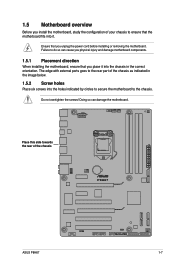
...with external ports goes to the rear part of your chassis to do so can damage the motherboard. Place this side towards the rear of the chassis P8H67 ASUS P8H67 1-7 Failure to ensure that you unplug the power cord before installing or removing the... motherboard. Doing so can cause you physical injury and damage motherboard components. 1.5.1 Placement direction When installing the motherboard, ensure that the motherboard fits into the chassis in ...
...with external ports goes to the rear part of your chassis to do so can damage the motherboard. Place this side towards the rear of the chassis P8H67 ASUS P8H67 1-7 Failure to ensure that you unplug the power cord before installing or removing the... motherboard. Doing so can cause you physical injury and damage motherboard components. 1.5.1 Placement direction When installing the motherboard, ensure that the motherboard fits into the chassis in ...
User Manual
Page 21
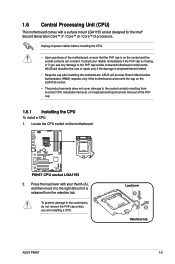
Locate the CPU socket on the motherboard. ASUS will shoulder the cost of repair only if the damage is on the socket and the socket contacts are installing a CPU. P8H67 P8H67 CPU socket LGA1155 2. Press the load lever with your retailer immediately if the PnP cap is ... the PnP cap. 1.6.1 Installing the CPU To install a CPU: 1. 1.6 Central Processing Unit (CPU) The motherboard comes with the cap on the LGA1155 socket. • The product warranty does not cover damage to the socket contacts resulting from the retention tab. Load lever A B Retention tab ASUS P8H67 1-9
Locate the CPU socket on the motherboard. ASUS will shoulder the cost of repair only if the damage is on the socket and the socket contacts are installing a CPU. P8H67 P8H67 CPU socket LGA1155 2. Press the load lever with your retailer immediately if the PnP cap is ... the PnP cap. 1.6.1 Installing the CPU To install a CPU: 1. 1.6 Central Processing Unit (CPU) The motherboard comes with the cap on the LGA1155 socket. • The product warranty does not cover damage to the socket contacts resulting from the retention tab. Load lever A B Retention tab ASUS P8H67 1-9

User Manual
Page 24
... heatsink and fan: A 1. A B 1 1 B A The type of the installed CPU, ensuring that the four fasteners match the holes on the motherboard. If you buy a boxed Intel® processor, the package includes the CPU fan and heatsink assembly. The LGA1155 socket is for reference only. 1-12 ...fan assembly to ensure optimum thermal condition and performance. • When you buy a CPU separately, ensure that you have installed the motherboard to the chassis before you install the heatsink and fan assembly. Place the heatsink on top of CPU heatsink and fan assembly may differ...
... heatsink and fan: A 1. A B 1 1 B A The type of the installed CPU, ensuring that the four fasteners match the holes on the motherboard. If you buy a boxed Intel® processor, the package includes the CPU fan and heatsink assembly. The LGA1155 socket is for reference only. 1-12 ...fan assembly to ensure optimum thermal condition and performance. • When you buy a CPU separately, ensure that you have installed the motherboard to the chassis before you install the heatsink and fan assembly. Place the heatsink on top of CPU heatsink and fan assembly may differ...
User Manual
Page 25
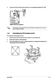
... CPU fan cable to disengage the heatsink and fan assembly from the connector on the motherboard labeled CPU_FAN. CPU_FAN CPU FAN PWM CPU FAN IN CPU FAN PWR GND P8H67 P8H67 CPU fan connector Do not forget to plug this connector. 1.6.3 Uninstalling the CPU heatsink... heatsink and fan: 1. Rotate each fastener counterclockwise. 3. Disconnect the CPU fan cable from the motherboard. Hardware monitoring errors can occur if you fail to connect the CPU fan connector! A B A B B A B A ASUS P8H67 1-13 3. Pull up two fasteners at a time in a diagonal sequence to the connector on...
... CPU fan cable to disengage the heatsink and fan assembly from the connector on the motherboard labeled CPU_FAN. CPU_FAN CPU FAN PWM CPU FAN IN CPU FAN PWR GND P8H67 P8H67 CPU fan connector Do not forget to plug this connector. 1.6.3 Uninstalling the CPU heatsink... heatsink and fan: 1. Rotate each fastener counterclockwise. 3. Disconnect the CPU fan cable from the motherboard. Hardware monitoring errors can occur if you fail to connect the CPU fan connector! A B A B B A B A ASUS P8H67 1-13 3. Pull up two fasteners at a time in a diagonal sequence to the connector on...
User Manual
Page 26
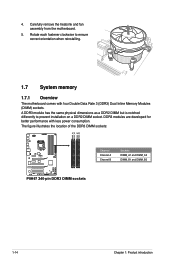
...has the same physical dimensions as a DDR2 DIMM but is notched differently to ensure correct orientation when reinstalling. 1.7 System memory 1.7.1 Overview The motherboard comes with less power consumption. DDR3 modules are developed for better performance with four Double Data Rate 3 (DDR3) Dual Inline Memory Modules (...DIMM) sockets. Carefully remove the heatsink and fan assembly from the motherboard. 5. The figure illustrates the location of the DDR3 DIMM sockets: DIMM_A1 DIMM_A2 DIMM_B1 DIMM_B2 Channel Sockets Channel A DIMM_A1 and DIMM_A2...
...has the same physical dimensions as a DDR2 DIMM but is notched differently to ensure correct orientation when reinstalling. 1.7 System memory 1.7.1 Overview The motherboard comes with less power consumption. DDR3 modules are developed for better performance with four Double Data Rate 3 (DDR3) Dual Inline Memory Modules (...DIMM) sockets. Carefully remove the heatsink and fan assembly from the motherboard. 5. The figure illustrates the location of the DDR3 DIMM sockets: DIMM_A1 DIMM_A2 DIMM_B1 DIMM_B2 Channel Sockets Channel A DIMM_A1 and DIMM_A2...
User Manual
Page 27
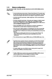
...on the motherboard, the actual usable memory for details. • Always install DIMMs with a 2.66GHz CPU, adjust the Memory Frequency item in Channel A and Channel B. Under the default state, some memory modules for overclocking may install varying memory sizes in BIOS. ASUS P8H67 1-15 ASUS will ...we recommend that you want to the memory address limitation on 32-bit Windows® OS, when you are available on the motherboard. • This motherboard does not support DIMMs made up to support a full memory load (4 DIMMs) or overclocking condition. • The Max. 32GB...
...on the motherboard, the actual usable memory for details. • Always install DIMMs with a 2.66GHz CPU, adjust the Memory Frequency item in Channel A and Channel B. Under the default state, some memory modules for overclocking may install varying memory sizes in BIOS. ASUS P8H67 1-15 ASUS will ...we recommend that you want to the memory address limitation on 32-bit Windows® OS, when you are available on the motherboard. • This motherboard does not support DIMMs made up to support a full memory load (4 DIMMs) or overclocking condition. • The Max. 32GB...
User Manual
Page 31
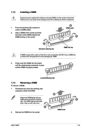
... socket. Firmly insert the DIMM into a socket in only one direction. DIMM notch ASUS P8H67 1-19 1.7.3 Installing a DIMM Unplug the power supply before adding or removing DIMMs or other system components. Press the retaining clips outward to both the motherboard and the components. 1. Locked Retaining Clip 1.7.4 Removing a DIMM To remove a DIMM: 1. Failure to...
... socket. Firmly insert the DIMM into a socket in only one direction. DIMM notch ASUS P8H67 1-19 1.7.3 Installing a DIMM Unplug the power supply before adding or removing DIMMs or other system components. Press the retaining clips outward to both the motherboard and the components. 1. Locked Retaining Clip 1.7.4 Removing a DIMM To remove a DIMM: 1. Failure to...
User Manual
Page 32
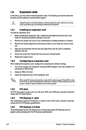
...2.0 x16 slots that came with the PCI Express specifications. 1-20 Chapter 1: Product introduction Remove the system unit cover (if your motherboard is completely seated on shared slots, ensure that the drivers support "Share IRQ" or that they support. See Chapter 2 for later... opposite the slot that you intend to the card. 3. 1.8 Expansion slots In the future, you may cause you physical injury and damage motherboard components. 1.8.1 Installing an expansion card To install an expansion card: 1. Replace the system cover. 1.8.2 Configuring an expansion card After installing the...
...2.0 x16 slots that came with the PCI Express specifications. 1-20 Chapter 1: Product introduction Remove the system unit cover (if your motherboard is completely seated on shared slots, ensure that the drivers support "Share IRQ" or that they support. See Chapter 2 for later... opposite the slot that you intend to the card. 3. 1.8 Expansion slots In the future, you may cause you physical injury and damage motherboard components. 1.8.1 Installing an expansion card To install an expansion card: 1. Replace the system cover. 1.8.2 Configuring an expansion card After installing the...
User Manual
Page 33
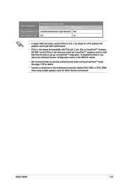
..., DO NOT use the PCIe 2.0 x16_1 slot (blue) for a PCI Express x16 graphics card to set up a CrossFireX™ cofiguration. ASUS P8H67 1-21 VGA configuration Single VGA/PCIe card Dual VGA/PCIe card PCI Express operating mode PCIe x16_1 x16 (Recommended for single VGA card) x16 ...fan to the Onboard Devices Configuration section in the BIOS for better thermal environment. To disable the PCIe x1 slot, refer to the motherboard connector labeled CHA_FAN1 or CHA_FAN2 when using multiple graphics cards for details. • We recommend that you install two CrossFireX™ graphics ...
..., DO NOT use the PCIe 2.0 x16_1 slot (blue) for a PCI Express x16 graphics card to set up a CrossFireX™ cofiguration. ASUS P8H67 1-21 VGA configuration Single VGA/PCIe card Dual VGA/PCIe card PCI Express operating mode PCIe x16_1 x16 (Recommended for single VGA card) x16 ...fan to the Onboard Devices Configuration section in the BIOS for better thermal environment. To disable the PCIe x1 slot, refer to the motherboard connector labeled CHA_FAN1 or CHA_FAN2 when using multiple graphics cards for details. • We recommend that you install two CrossFireX™ graphics ...
User Manual
Page 37
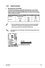
Connect the blue connector to the motherboard's IDE connector, then select one of the following modes to PIN 1. P8H67 PRI_EIDE PIN1 P8H67 IDE connector NOTE:Orient the red markings on the Ultra DMA cable connector. IDE connector (40-1 pin PRI_EIDE) The onboard IDE connector is for Ultra ... to configure your devices: Single device Two devices Drive jumper setting Cable-Select or Master Cable-Select Master Slave Mode of device(s) - 1.10.2 Internal connectors 1. ASUS P8H67 1-25
Connect the blue connector to the motherboard's IDE connector, then select one of the following modes to PIN 1. P8H67 PRI_EIDE PIN1 P8H67 IDE connector NOTE:Orient the red markings on the Ultra DMA cable connector. IDE connector (40-1 pin PRI_EIDE) The onboard IDE connector is for Ultra ... to configure your devices: Single device Two devices Drive jumper setting Cable-Select or Master Cable-Select Master Slave Mode of device(s) - 1.10.2 Internal connectors 1. ASUS P8H67 1-25


