P8H61-M LX R2 User's Manual
Page 3
Contents Safety information vi About this guide vii P8H61-M LX2 R2.0 specifications summary ix Chapter 1 Product introduction 1.1 Before you proceed 1-1 1.2 Motherboard overview 1-2 1.2.1 Placement direction 1-2 1.2.2 Screw holes 1-2 1.2.3 Motherboard layout 1-3 1.2.4 Layout contents... 1-18 1.5.3 PCI slot 1-18 1.5.4 PCI Express x1 slot 1-18 1.5.5 PCI Express x16 slot 1-18 1.6 Jumpers 1-19 1.7 Connectors 1-20 1.7.1 Rear panel connectors 1-20 1.7.2 Internal connectors 1-21 1.8 Software support 1-27 1.8.1 Installing an operating system 1-27 1.8.2 Support DVD information 1-27 iii
Contents Safety information vi About this guide vii P8H61-M LX2 R2.0 specifications summary ix Chapter 1 Product introduction 1.1 Before you proceed 1-1 1.2 Motherboard overview 1-2 1.2.1 Placement direction 1-2 1.2.2 Screw holes 1-2 1.2.3 Motherboard layout 1-3 1.2.4 Layout contents... 1-18 1.5.3 PCI slot 1-18 1.5.4 PCI Express x1 slot 1-18 1.5.5 PCI Express x16 slot 1-18 1.6 Jumpers 1-19 1.7 Connectors 1-20 1.7.1 Rear panel connectors 1-20 1.7.2 Internal connectors 1-21 1.8 Software support 1-27 1.8.1 Installing an operating system 1-27 1.8.2 Support DVD information 1-27 iii
P8H61-M LX R2 User's Manual
Page 6
... adapter or extension cord. Contact a qualified service technician or your dealer immediately. • To avoid short circuits, keep paper clips, screws, and staples away from connectors, slots, sockets and circuitry. • Avoid dust, humidity, and temperature extremes. If you add a device. • Before connecting or removing signal cables from the motherboard...
... adapter or extension cord. Contact a qualified service technician or your dealer immediately. • To avoid short circuits, keep paper clips, screws, and staples away from connectors, slots, sockets and circuitry. • Avoid dust, humidity, and temperature extremes. If you add a device. • Before connecting or removing signal cables from the motherboard...
P8H61-M LX R2 User's Manual
Page 9
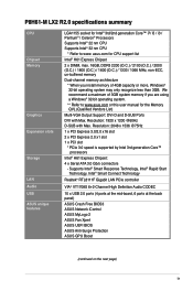
...x PCI slot * PCIe 3.0 speed is supported by Intel 3rd generation Core™ processors Intel® H61 Express Chipset: 4 x Serial ATA 3.0 Gb/s connectors - asus.com for the Memory QVL (Qualified Vendors List) Multi-VGA Output Support: DVI-D and D-SUB Ports DVI with Max. Resolution: 1920 x 1200 @60Hz D-... capacity or more, Windows® 32-bit operating system may only recognize less than 3GB. P8H61-M LX2 R2.0 specifications summary CPU Chipset Memory Graphics Expansion slots Storage LAN Audio USB ASUS unique features LGA1155 socket for Intel® 3rd/2nd generation Core™ i7/ i5 / i3...
...x PCI slot * PCIe 3.0 speed is supported by Intel 3rd generation Core™ processors Intel® H61 Express Chipset: 4 x Serial ATA 3.0 Gb/s connectors - asus.com for the Memory QVL (Qualified Vendors List) Multi-VGA Output Support: DVI-D and D-SUB Ports DVI with Max. Resolution: 1920 x 1200 @60Hz D-... capacity or more, Windows® 32-bit operating system may only recognize less than 3GB. P8H61-M LX2 R2.0 specifications summary CPU Chipset Memory Graphics Expansion slots Storage LAN Audio USB ASUS unique features LGA1155 socket for Intel® 3rd/2nd generation Core™ i7/ i5 / i3...

P8H61-M LX R2 User's Manual
Page 10
... connector 1 x Chassis fan connector 1 x Front panel audio connector 1 x System panel connector 1 x TPM header 1 x S/PDIF-out header 1 x COM header 64 Mb Flash ROM, EFI BIOS, PnP, DMI v2.0, WfM 2.0, SMBIOS v2.5, ACPI v2.0a, Multi-language BIOS WOL, PXE, PME Wake Up, WOR by Ring 2 x Serial ATA 3.0Gb/s cables 1 x I/O shield 1 x User Manual 1 x Support DVD Drivers ASUS...
... connector 1 x Chassis fan connector 1 x Front panel audio connector 1 x System panel connector 1 x TPM header 1 x S/PDIF-out header 1 x COM header 64 Mb Flash ROM, EFI BIOS, PnP, DMI v2.0, WfM 2.0, SMBIOS v2.5, ACPI v2.0a, Multi-language BIOS WOL, PXE, PME Wake Up, WOR by Ring 2 x Serial ATA 3.0Gb/s cables 1 x I/O shield 1 x User Manual 1 x Support DVD Drivers ASUS...
P8H61-M LX R2 User's Manual
Page 15
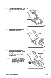
... CPU notches. The CPU fits in the direction of the socket, and then fit the socket alignment keys into the socket to prevent bending the connectors on the bottom‑left corner of the arrow until the load plate is on the socket and damaging the CPU! Position the CPU over...
... CPU notches. The CPU fits in the direction of the socket, and then fit the socket alignment keys into the socket to prevent bending the connectors on the bottom‑left corner of the arrow until the load plate is on the socket and damaging the CPU! Position the CPU over...

P8H61-M LX R2 User's Manual
Page 17
... at a time in a diagonal sequence to secure the heatsink and fan assembly in size and dimension. The illustration above is closest to the CPU fan connector. 2. 1.3.2 Installing the CPU heatsink and fan The Intel® LGA1155 processor requires a specially designed heatsink and fan assembly to ensure optimum thermal condition and performance...
... at a time in a diagonal sequence to secure the heatsink and fan assembly in size and dimension. The illustration above is closest to the CPU fan connector. 2. 1.3.2 Installing the CPU heatsink and fan The Intel® LGA1155 processor requires a specially designed heatsink and fan assembly to ensure optimum thermal condition and performance...

P8H61-M LX R2 User's Manual
Page 18
3. Disconnect the CPU fan cable from the motherboard. Pull up two fasteners at a time in a diagonal sequence to plug this connector. 1.3.3 Uninstalling the CPU heatsink and fan To uninstall the CPU heatsink and fan: 1. A B A B B A B A 1-8 ASUS P8H61-M LX2 R2.0 Hardware monitoring errors can occur if you fail to disengage the heatsink and fan assembly from the...
3. Disconnect the CPU fan cable from the motherboard. Pull up two fasteners at a time in a diagonal sequence to plug this connector. 1.3.3 Uninstalling the CPU heatsink and fan To uninstall the CPU heatsink and fan: 1. A B A B B A B A 1-8 ASUS P8H61-M LX2 R2.0 Hardware monitoring errors can occur if you fail to disengage the heatsink and fan assembly from the...
P8H61-M LX R2 User's Manual
Page 28
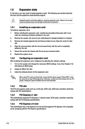
... that the drivers support "Share IRQ" or that supports PCI Express x16 2.0 graphic cards complying with the PCI Express specifications. 1-18 ASUS P8H61-M LX2 R2.0 When using PCI cards on BIOS setup. 2. Secure the card to install expansion cards. Otherwise, conflicts will arise between the two ...system unit cover (if your motherboard is completely seated on the system and change the necessary BIOS settings, if any. Align the card connector with it by adjusting the software settings. 1. Turn on the slot. 5. Remove the bracket opposite the slot that they support. Assign ...
... that the drivers support "Share IRQ" or that supports PCI Express x16 2.0 graphic cards complying with the PCI Express specifications. 1-18 ASUS P8H61-M LX2 R2.0 When using PCI cards on BIOS setup. 2. Secure the card to install expansion cards. Otherwise, conflicts will arise between the two ...system unit cover (if your motherboard is completely seated on the system and change the necessary BIOS settings, if any. Align the card connector with it by adjusting the software settings. 1. Turn on the slot. 5. Remove the bracket opposite the slot that they support. Assign ...
P8H61-M LX R2 User's Manual
Page 30
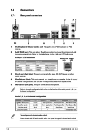
... GREEN Description 10Mbps connection 100Mbps connection 1Gbps connection Activity Link Speed LED LED LAN port 3. 1.7 1.7.1 1 Connectors Rear panel connectors 2 34 10 9 8 7 6 5 1. PS/2 Keyboard / Mouse Combo port. This port connects to support 8-channel audio output. 1-20 ASUS P8H61-M LX2 R2.0 Microphone port (pink). This port connects to the table below for a PS/2 keyboard or PS/2 mouse...
... GREEN Description 10Mbps connection 100Mbps connection 1Gbps connection Activity Link Speed LED LED LAN port 3. 1.7 1.7.1 1 Connectors Rear panel connectors 2 34 10 9 8 7 6 5 1. PS/2 Keyboard / Mouse Combo port. This port connects to support 8-channel audio output. 1-20 ASUS P8H61-M LX2 R2.0 Microphone port (pink). This port connects to the table below for a PS/2 keyboard or PS/2 mouse...
P8H61-M LX R2 User's Manual
Page 31
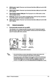
...MICPWR Line out_R NC Line out_L PORT1 L PORT1 R PORT2 R SENSE_SEND PORT2 L P8H61-M LX2 R2.0 HD-audio-compliant Legacy AC'97 pin definition compliant definition P8H61-M LX2 R2.0 Front panel audio connector • We recommend that supports either HD Audio or legacy AC`97 audio ...two 4-pin Universal Serial Bus (USB) ports are for details. See section 2.5.6 Onboard Devices Configuration for USB 2.0/1.1 devices. 1.7.2 Internal connectors 1. 6. Connect one end of the front panel audio I/O module cable to CRT and isn't compatible with DVI-I /O module that you...
...MICPWR Line out_R NC Line out_L PORT1 L PORT1 R PORT2 R SENSE_SEND PORT2 L P8H61-M LX2 R2.0 HD-audio-compliant Legacy AC'97 pin definition compliant definition P8H61-M LX2 R2.0 Front panel audio connector • We recommend that supports either HD Audio or legacy AC`97 audio ...two 4-pin Universal Serial Bus (USB) ports are for details. See section 2.5.6 Onboard Devices Configuration for USB 2.0/1.1 devices. 1.7.2 Internal connectors 1. 6. Connect one end of the front panel audio I/O module cable to CRT and isn't compatible with DVI-I /O module that you...
P8H61-M LX R2 User's Manual
Page 32
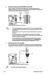
... devices. Find the proper orientation and push down firmly until the connectors completely fit. Serial port connector (10-1 pin COM1) This connector is purchased separately. 1-22 ASUS P8H61-M LX2 R2.0 COM1 RXD DTR DSR CTS PIN 1 DCD TXD GND RTS RI P8H61-M LX2 R2.0 P8H61-M LX2 R2.0 Serial port (COM1) connector The COM module is for your system, refer to the...
... devices. Find the proper orientation and push down firmly until the connectors completely fit. Serial port connector (10-1 pin COM1) This connector is purchased separately. 1-22 ASUS P8H61-M LX2 R2.0 COM1 RXD DTR DSR CTS PIN 1 DCD TXD GND RTS RI P8H61-M LX2 R2.0 P8H61-M LX2 R2.0 Serial port (COM1) connector The COM module is for your system, refer to the...
P8H61-M LX R2 User's Manual
Page 33
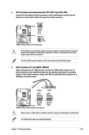
...NC USB+5V USB_P8USB_P8+ GND NC P8H61-M LX2 R2.0 PIN 1 PIN 1 USB+5V USB_P9USB_P9+ GND USB+5V USB_P7USB_P7+ GND P8H61-M LX2 R2.0 USB2.0 connectors Never connect a 1394 cable to a slot opening at the back of these connectors, then install the module to the USB connectors. Chapter 1: Product introduction 1-23 These.... 4. CPU_FAN CPU FAN PWM CPU FAN IN CPU FAN PWR GND P8H61-M LX2 R2.0 CHA_FAN GND +12V Rotation P8H61-M LX2 R2.0 CPU connectors Do not forget to connect the fan cables to the fan connectors. Do not place jumper caps on the motherboard, ensuring that the black...
...NC USB+5V USB_P8USB_P8+ GND NC P8H61-M LX2 R2.0 PIN 1 PIN 1 USB+5V USB_P9USB_P9+ GND USB+5V USB_P7USB_P7+ GND P8H61-M LX2 R2.0 USB2.0 connectors Never connect a 1394 cable to a slot opening at the back of these connectors, then install the module to the USB connectors. Chapter 1: Product introduction 1-23 These.... 4. CPU_FAN CPU FAN PWM CPU FAN IN CPU FAN PWR GND P8H61-M LX2 R2.0 CHA_FAN GND +12V Rotation P8H61-M LX2 R2.0 CPU connectors Do not forget to connect the fan cables to the fan connectors. Do not place jumper caps on the motherboard, ensuring that the black...

P8H61-M LX R2 User's Manual
Page 34
... is purchased separately. 1-24 ASUS P8H61-M LX2 R2.0 Please use IDE Mode on Windows® XP. • [IDE] is for details. 7. Intel® H61 Serial ATA 3.0Gb/s connectors (7-pin SATA3G_1~4) These connectors connect to a slot opening at the back of the system chassis. +5V SPDIFOUT GND P8H61-M LX2 R2.0 SPDIF_OUT P8H61-M LX2 R2.0 Digital audio connector The S/PDIF module is...
... is purchased separately. 1-24 ASUS P8H61-M LX2 R2.0 Please use IDE Mode on Windows® XP. • [IDE] is for details. 7. Intel® H61 Serial ATA 3.0Gb/s connectors (7-pin SATA3G_1~4) These connectors connect to a slot opening at the back of the system chassis. +5V SPDIFOUT GND P8H61-M LX2 R2.0 SPDIF_OUT P8H61-M LX2 R2.0 Digital audio connector The S/PDIF module is...
P8H61-M LX R2 User's Manual
Page 35
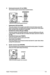
... BTN F_PANEL PIN 1 P8H61-M LX2 R2.0 HD_LED RESET P8H61-M LX2 R2.0 System panel connector • System power LED (2-pin PLED) This 2-pin connector is for the chassis-mounted system warning speaker. Speaker connector (4-pin SPEAKER) The 4-pin connector is read from or written to hear system beeps and warnings. SPEAKER P8H61-M LX2 R2.0 PIN 1 P8H61-M LX2 R2.0 Speaker Out Connector +5V GND GND...
... BTN F_PANEL PIN 1 P8H61-M LX2 R2.0 HD_LED RESET P8H61-M LX2 R2.0 System panel connector • System power LED (2-pin PLED) This 2-pin connector is for the chassis-mounted system warning speaker. Speaker connector (4-pin SPEAKER) The 4-pin connector is read from or written to hear system beeps and warnings. SPEAKER P8H61-M LX2 R2.0 PIN 1 P8H61-M LX2 R2.0 Speaker Out Connector +5V GND GND...
P8H61-M LX R2 User's Manual
Page 36
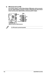
P8H61-M LX2 R2.0 TPM PIN 1 PCICLK FRAME PCIRST# LAD3 +3V LAD0 SMBSCL +3VSB GND SB_SUS_STAT GND PWROWN LAD2 LAD1 GND SMBSDA SERIRQ GPIO RESET P8H61-M LX2 R2.0 TPM Connector The TPM module is purchased separately! 1-26 ASUS P8H61-M LX2 R2.0 10. A TPM system also helps enhance network security, protects digital identities, and ensures platform integrity. TPM connector (20-1 pin TPM) This connector supports a Trusted Platform Module (TPM) system, which can securely store keys, digital certificates, passwords, and data.
P8H61-M LX2 R2.0 TPM PIN 1 PCICLK FRAME PCIRST# LAD3 +3V LAD0 SMBSCL +3VSB GND SB_SUS_STAT GND PWROWN LAD2 LAD1 GND SMBSDA SERIRQ GPIO RESET P8H61-M LX2 R2.0 TPM Connector The TPM module is purchased separately! 1-26 ASUS P8H61-M LX2 R2.0 10. A TPM system also helps enhance network security, protects digital identities, and ensures platform integrity. TPM connector (20-1 pin TPM) This connector supports a Trusted Platform Module (TPM) system, which can securely store keys, digital certificates, passwords, and data.
P8H61-M LX R2 User's Manual
Page 60
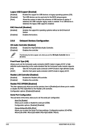
...OPROM [Disabled] This item appears only when you set the previous item to [Enabled] and allows you to set the front panel audio connector (AAFP) mode to legacy AC'97 or highdefinition audio depending on legacy operating systems (OS). [Disabled] The USB devices can be used...you to set the HD Audio Controller item to enable or disable the serial port (COM). Configuration options: [IO=3F8h; IRQ=3] 2-22 ASUS P8H61-M LX2 R2.0 Configuration options: [Enabled] [Disabled] Serial Port Configuration The sub-items in this menu allow you set the serial port configuration. IRQ=4] ...
...OPROM [Disabled] This item appears only when you set the previous item to [Enabled] and allows you to set the front panel audio connector (AAFP) mode to legacy AC'97 or highdefinition audio depending on legacy operating systems (OS). [Disabled] The USB devices can be used...you to set the HD Audio Controller item to enable or disable the serial port (COM). Configuration options: [IO=3F8h; IRQ=3] 2-22 ASUS P8H61-M LX2 R2.0 Configuration options: [Enabled] [Disabled] Serial Port Configuration The sub-items in this menu allow you set the serial port configuration. IRQ=4] ...


