
P8H61-M LX R2 User's Manual
Page 1
Motherboard P8H61-M LX2 R2.0
Motherboard P8H61-M LX2 R2.0
P8H61-M LX R2 User's Manual
Page 3
Contents Safety information vi About this guide vii P8H61-M LX2 R2.0 specifications summary ix Chapter 1 Product introduction 1.1 Before you proceed 1-1 1.2 Motherboard overview 1-2 1.2.1 Placement direction 1-2 1.2.2 Screw holes 1-2 1.2.3 Motherboard layout 1-3 1.2.4 Layout contents 1-3 1.3 Central Processing Unit (CPU 1-4 1.3.1 Installing the ...
Contents Safety information vi About this guide vii P8H61-M LX2 R2.0 specifications summary ix Chapter 1 Product introduction 1.1 Before you proceed 1-1 1.2 Motherboard overview 1-2 1.2.1 Placement direction 1-2 1.2.2 Screw holes 1-2 1.2.3 Motherboard layout 1-3 1.2.4 Layout contents 1-3 1.3 Central Processing Unit (CPU 1-4 1.3.1 Installing the ...
P8H61-M LX R2 User's Manual
Page 9
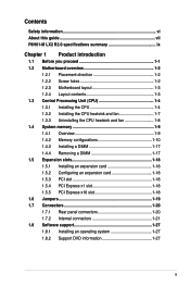
... is supported by Intel 3rd generation Core™ processors Intel® H61 Express Chipset: 4 x Serial ATA 3.0 Gb/s connectors - P8H61-M LX2 R2.0 specifications summary CPU Chipset Memory Graphics Expansion slots Storage LAN Audio USB ASUS unique features LGA1155 socket for Intel® 3rd/2nd generation Core™ i7/ i5 / i3 / Pentium® / Celeron®...
... is supported by Intel 3rd generation Core™ processors Intel® H61 Express Chipset: 4 x Serial ATA 3.0 Gb/s connectors - P8H61-M LX2 R2.0 specifications summary CPU Chipset Memory Graphics Expansion slots Storage LAN Audio USB ASUS unique features LGA1155 socket for Intel® 3rd/2nd generation Core™ i7/ i5 / i3 / Pentium® / Celeron®...
P8H61-M LX R2 User's Manual
Page 11
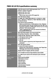
... on a grounded antistatic pad or in any motherboard component. Refer to page x for buying an ASUS® P8H61-M LX2 R2.0 Series motherboard! The illustration below shows the location of the items is damaged or missing, contact your motherboard package. SB_PWR... P8H61-M LX2 R2.0 ON OFF Standby Power Powered Off P8H61-M LX2 R2.0 Onboard LED Chapter 1: Product introduction 1-1 Chapter 1 Product introduction Thank you install motherboard components or change...
... on a grounded antistatic pad or in any motherboard component. Refer to page x for buying an ASUS® P8H61-M LX2 R2.0 Series motherboard! The illustration below shows the location of the items is damaged or missing, contact your motherboard package. SB_PWR... P8H61-M LX2 R2.0 ON OFF Standby Power Powered Off P8H61-M LX2 R2.0 Onboard LED Chapter 1: Product introduction 1-1 Chapter 1 Product introduction Thank you install motherboard components or change...
P8H61-M LX R2 User's Manual
Page 12
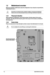
Place this side towards the rear of the chassis P8H61-M LX2 R2.0 1-2 ASUS P8H61-M LX2 R2.0 Do not overtighten the screws! Failure to do so can damage the motherboard. Doing so can cause you physical injury and damage motherboard components. 1.2.1 Placement ...
Place this side towards the rear of the chassis P8H61-M LX2 R2.0 1-2 ASUS P8H61-M LX2 R2.0 Do not overtighten the screws! Failure to do so can damage the motherboard. Doing so can cause you physical injury and damage motherboard components. 1.2.1 Placement ...
P8H61-M LX R2 User's Manual
Page 14
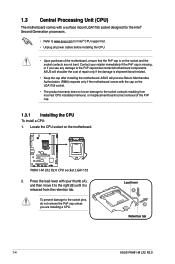
... the socket and the socket contacts are installing a CPU. Load lever A B Retention tab 1-4 ASUS P8H61-M LX2 R2.0 ASUS will process Return Merchandise Authorization (RMA) requests only if the motherboard comes with the cap on the motherboard. P8H61-M LX2 R2.0 P8H61-M LX2 R2.0 CPU socket LGA1155 2. ASUS will shoulder the cost of repair only if the damage is shipment/transit...
... the socket and the socket contacts are installing a CPU. Load lever A B Retention tab 1-4 ASUS P8H61-M LX2 R2.0 ASUS will process Return Merchandise Authorization (RMA) requests only if the motherboard comes with the cap on the motherboard. P8H61-M LX2 R2.0 P8H61-M LX2 R2.0 CPU socket LGA1155 2. ASUS will shoulder the cost of repair only if the damage is shipment/transit...
P8H61-M LX R2 User's Manual
Page 16
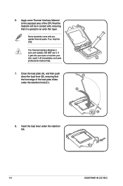
... the load lever under the retention knob (C). Apply some Thermal Interface Material to the exposed area of the load plate slides under the retention tab. 1-6 ASUS P8H61-M LX2 R2.0 B A C 8. DO NOT eat it off immediately, and seek professional medical help. 7. Some heatsinks come with , ensuring that the front edge of the CPU that...
... the load lever under the retention knob (C). Apply some Thermal Interface Material to the exposed area of the load plate slides under the retention tab. 1-6 ASUS P8H61-M LX2 R2.0 B A C 8. DO NOT eat it off immediately, and seek professional medical help. 7. Some heatsinks come with , ensuring that the front edge of the CPU that...

P8H61-M LX R2 User's Manual
Page 18
CPU_FAN CPU FAN PWM CPU FAN IN CPU FAN PWR GND P8H61-M LX2 R2.0 P8H61-M LX2 R2.0 CPU fan connector Do not forget to plug this connector. 1.3.3 Uninstalling the CPU heatsink and fan To uninstall the CPU heatsink and fan: 1. Hardware monitoring ... motherboard. Rotate each fastener counterclockwise. 3. 3. Connect the CPU fan cable to disengage the heatsink and fan assembly from the connector on the motherboard labeled CPU_FAN. A B A B B A B A 1-8 ASUS P8H61-M LX2 R2.0
CPU_FAN CPU FAN PWM CPU FAN IN CPU FAN PWR GND P8H61-M LX2 R2.0 P8H61-M LX2 R2.0 CPU fan connector Do not forget to plug this connector. 1.3.3 Uninstalling the CPU heatsink and fan To uninstall the CPU heatsink and fan: 1. Hardware monitoring ... motherboard. Rotate each fastener counterclockwise. 3. 3. Connect the CPU fan cable to disengage the heatsink and fan assembly from the connector on the motherboard labeled CPU_FAN. A B A B B A B A 1-8 ASUS P8H61-M LX2 R2.0
P8H61-M LX R2 User's Manual
Page 19
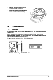
4. The figure illustrates the location of the DDR3 DIMM sockets: DIMM_A1 DIMM_B1 P8H61-M LX2 R2.0 Channel Channel A Channel B Sockets DIMM_A1 DIMM_B1 P8H61-M LX2 R2.0 240-pin DDR3 DIMM sockets Chapter 1: Product introduction 1-9 A DDR3 module has the same physical dimensions as a DDR2 DIMM but is notched differently to ensure correct ...
4. The figure illustrates the location of the DDR3 DIMM sockets: DIMM_A1 DIMM_B1 P8H61-M LX2 R2.0 Channel Channel A Channel B Sockets DIMM_A1 DIMM_B1 P8H61-M LX2 R2.0 240-pin DDR3 DIMM sockets Chapter 1: Product introduction 1-9 A DDR3 module has the same physical dimensions as a DDR2 DIMM but is notched differently to ensure correct ...
P8H61-M LX R2 User's Manual
Page 20
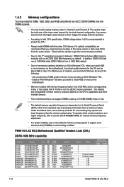
...DS ELPIDA J1108BDSE-DJ-F 7 1.5V KINGSTON KVR1066D3N7/4G 4GB DS Hynix H5TQ2G83AFR 7 1.5V Kingtiger 2GB DIMM PC3-8500 2GB DS Hynix H5TQ1G83AFP G7C - - 1-10 ASUS P8H61-M LX2 R2.0 For optimal compatibility, we recommend that you do any of 3GB system memory if you install 4GB or more efficient memory cooling system to install... sockets. • You may operate at a lower frequency than 2133 MHz and its Serial Presence Detect (SPD), which is not the JEDEC memory standard. P8H61-M LX2 R2.0 Motherboard Qualified Vendors Lists (QVL) DDR3-1066 MHz capability Vendors Part No.
...DS ELPIDA J1108BDSE-DJ-F 7 1.5V KINGSTON KVR1066D3N7/4G 4GB DS Hynix H5TQ2G83AFR 7 1.5V Kingtiger 2GB DIMM PC3-8500 2GB DS Hynix H5TQ1G83AFP G7C - - 1-10 ASUS P8H61-M LX2 R2.0 For optimal compatibility, we recommend that you do any of 3GB system memory if you install 4GB or more efficient memory cooling system to install... sockets. • You may operate at a lower frequency than 2133 MHz and its Serial Presence Detect (SPD), which is not the JEDEC memory standard. P8H61-M LX2 R2.0 Motherboard Qualified Vendors Lists (QVL) DDR3-1066 MHz capability Vendors Part No.
P8H61-M LX R2 User's Manual
Page 26
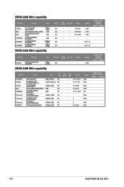
... - 9-11-9-27 - 10-11-10-30 - - - 9 - 9 - 9-11-9-27 Voltage 1.65V 1.65V 1.65V 1.65V 1.8V 1.65V 1.65V 1.65V 1.65V DIMM socket support (optional) 1DIMM 2DIMMs 1-16 ASUS P8H61-M LX2 R2.0
... - 9-11-9-27 - 10-11-10-30 - - - 9 - 9 - 9-11-9-27 Voltage 1.65V 1.65V 1.65V 1.65V 1.8V 1.65V 1.65V 1.65V 1.65V DIMM socket support (optional) 1DIMM 2DIMMs 1-16 ASUS P8H61-M LX2 R2.0
P8H61-M LX R2 User's Manual
Page 28
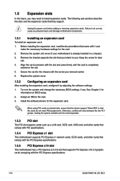
... (if your motherboard is completely seated on shared slots, ensure that the drivers support "Share IRQ" or that came with the PCI Express specifications. 1-18 ASUS P8H61-M LX2 R2.0 Secure the card to use . 4. Align the card connector with the screw you removed earlier. 6. Remove the bracket opposite the slot that they support...
... (if your motherboard is completely seated on shared slots, ensure that the drivers support "Share IRQ" or that came with the PCI Express specifications. 1-18 ASUS P8H61-M LX2 R2.0 Secure the card to use . 4. Align the card connector with the screw you removed earlier. 6. Remove the bracket opposite the slot that they support...
P8H61-M LX R2 User's Manual
Page 29
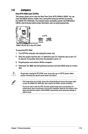
... the RTC when the system hangs due to re-enter data. Shut down the key during the boot process and enter BIOS setup to overclocking. P8H61-M LX2 R2.0 CLRTC 12 23 Normal (Default) Clear RTC P8H61-M LX2 R2.0 Clear RTC RAM To erase the RTC RAM: 1.
... the RTC when the system hangs due to re-enter data. Shut down the key during the boot process and enter BIOS setup to overclocking. P8H61-M LX2 R2.0 CLRTC 12 23 Normal (Default) Clear RTC P8H61-M LX2 R2.0 Clear RTC RAM To erase the RTC RAM: 1.
P8H61-M LX R2 User's Manual
Page 30
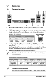
... in 2, 4, 6, or 8-channel configuration. In the 4, 6, and 8-channel configurations, the function of the audio ports in the front panel to support 8-channel audio output. 1-20 ASUS P8H61-M LX2 R2.0 1.7 1.7.1 1 Connectors Rear panel connectors 2 34 10 9 8 7 6 5 1.
... in 2, 4, 6, or 8-channel configuration. In the 4, 6, and 8-channel configurations, the function of the audio ports in the front panel to support 8-channel audio output. 1-20 ASUS P8H61-M LX2 R2.0 1.7 1.7.1 1 Connectors Rear panel connectors 2 34 10 9 8 7 6 5 1.
P8H61-M LX R2 User's Manual
Page 31
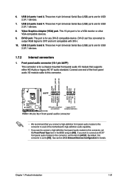
... AGND NC NC NC AAFP PIN 1 PIN 1 MIC2 MICPWR Line out_R NC Line out_L PORT1 L PORT1 R PORT2 R SENSE_SEND PORT2 L P8H61-M LX2 R2.0 HD-audio-compliant Legacy AC'97 pin definition compliant definition P8H61-M LX2 R2.0 Front panel audio connector • We recommend that supports either HD Audio or legacy AC`97 audio standard. This...
... AGND NC NC NC AAFP PIN 1 PIN 1 MIC2 MICPWR Line out_R NC Line out_L PORT1 L PORT1 R PORT2 R SENSE_SEND PORT2 L P8H61-M LX2 R2.0 HD-audio-compliant Legacy AC'97 pin definition compliant definition P8H61-M LX2 R2.0 Front panel audio connector • We recommend that supports either HD Audio or legacy AC`97 audio standard. This...
P8H61-M LX R2 User's Manual
Page 32
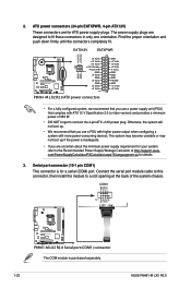
...serial (COM) port. Serial port connector (10-1 pin COM1) This connector is purchased separately. 1-22 ASUS P8H61-M LX2 R2.0 COM1 RXD DTR DSR CTS PIN 1 DCD TXD GND RTS RI P8H61-M LX2 R2.0 P8H61-M LX2 R2.0 Serial port (COM1) connector The COM module is for your system, refer to a slot opening at... http://support.asus. EATX12V EATXPWR +12V DC +12V DC P8H61-M LX2 R2.0 GND GND +3 Volts +12 Volts +12 Volts +5V...
...serial (COM) port. Serial port connector (10-1 pin COM1) This connector is purchased separately. 1-22 ASUS P8H61-M LX2 R2.0 COM1 RXD DTR DSR CTS PIN 1 DCD TXD GND RTS RI P8H61-M LX2 R2.0 P8H61-M LX2 R2.0 Serial port (COM1) connector The COM module is for your system, refer to a slot opening at... http://support.asus. EATX12V EATXPWR +12V DC +12V DC P8H61-M LX2 R2.0 GND GND +3 Volts +12 Volts +12 Volts +5V...
P8H61-M LX R2 User's Manual
Page 33
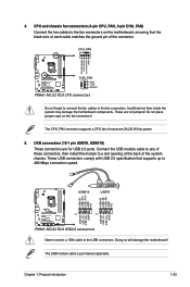
CPU_FAN CPU FAN PWM CPU FAN IN CPU FAN PWR GND P8H61-M LX2 R2.0 CHA_FAN GND +12V Rotation P8H61-M LX2 R2.0 CPU connectors Do not forget to connect the fan cables to the USB connectors. USB connectors (10-1 pin USB78, USB910) These connectors...matches the ground pin of the connector. USB910 USB78 USB+5V USB_P10USB_P10+ GND NC USB+5V USB_P8USB_P8+ GND NC P8H61-M LX2 R2.0 PIN 1 PIN 1 USB+5V USB_P9USB_P9+ GND USB+5V USB_P7USB_P7+ GND P8H61-M LX2 R2.0 USB2.0 connectors Never connect a 1394 cable to the fan connectors. Chapter 1: Product introduction 1-23 4. Insufficient ...
CPU_FAN CPU FAN PWM CPU FAN IN CPU FAN PWR GND P8H61-M LX2 R2.0 CHA_FAN GND +12V Rotation P8H61-M LX2 R2.0 CPU connectors Do not forget to connect the fan cables to the USB connectors. USB connectors (10-1 pin USB78, USB910) These connectors...matches the ground pin of the connector. USB910 USB78 USB+5V USB_P10USB_P10+ GND NC USB+5V USB_P8USB_P8+ GND NC P8H61-M LX2 R2.0 PIN 1 PIN 1 USB+5V USB_P9USB_P9+ GND USB+5V USB_P7USB_P7+ GND P8H61-M LX2 R2.0 USB2.0 connectors Never connect a 1394 cable to the fan connectors. Chapter 1: Product introduction 1-23 4. Insufficient ...

P8H61-M LX R2 User's Manual
Page 34
... set the SATA Mode item in the BIOS to a slot opening at the back of the system chassis. +5V SPDIFOUT GND P8H61-M LX2 R2.0 SPDIF_OUT P8H61-M LX2 R2.0 Digital audio connector The S/PDIF module is for details. 7. Under Windows® XP, there is the default SATA type. ... and optical drives via Serial ATA 3.0 Gb/s signal cables. Digital audio connector (4-1 pin SPDIF_OUT) This connector is purchased separately. 1-24 ASUS P8H61-M LX2 R2.0 Connect the S/PDIF Out module cable to this connector, then install the module to [AHCI Mode]. See section 2.5.4 SATA Configuration for an...
... set the SATA Mode item in the BIOS to a slot opening at the back of the system chassis. +5V SPDIFOUT GND P8H61-M LX2 R2.0 SPDIF_OUT P8H61-M LX2 R2.0 Digital audio connector The S/PDIF module is for details. 7. Under Windows® XP, there is the default SATA type. ... and optical drives via Serial ATA 3.0 Gb/s signal cables. Digital audio connector (4-1 pin SPDIF_OUT) This connector is purchased separately. 1-24 ASUS P8H61-M LX2 R2.0 Connect the S/PDIF Out module cable to this connector, then install the module to [AHCI Mode]. See section 2.5.4 SATA Configuration for an...
P8H61-M LX R2 User's Manual
Page 35
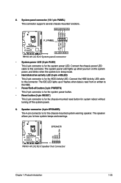
PWR LED PWR BTN F_PANEL PIN 1 P8H61-M LX2 R2.0 HD_LED RESET P8H61-M LX2 R2.0 System panel connector • System power LED (2-pin PLED) This 2-pin connector is for system reboot without turning off button (2-pin PWRBTN) This 2-pin connector ... when data is for the chassis-mounted reset button for the system power LED. Connect the HDD Activity LED cable to this connector. SPEAKER P8H61-M LX2 R2.0 PIN 1 P8H61-M LX2 R2.0 Speaker Out Connector +5V GND GND Speaker Out Chapter 1: Product introduction 1-25 Ground Reset 8. The speaker allows you turn on the system power...
PWR LED PWR BTN F_PANEL PIN 1 P8H61-M LX2 R2.0 HD_LED RESET P8H61-M LX2 R2.0 System panel connector • System power LED (2-pin PLED) This 2-pin connector is for system reboot without turning off button (2-pin PWRBTN) This 2-pin connector ... when data is for the chassis-mounted reset button for the system power LED. Connect the HDD Activity LED cable to this connector. SPEAKER P8H61-M LX2 R2.0 PIN 1 P8H61-M LX2 R2.0 Speaker Out Connector +5V GND GND Speaker Out Chapter 1: Product introduction 1-25 Ground Reset 8. The speaker allows you turn on the system power...
P8H61-M LX R2 User's Manual
Page 36
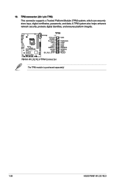
TPM connector (20-1 pin TPM) This connector supports a Trusted Platform Module (TPM) system, which can securely store keys, digital certificates, passwords, and data. A TPM system also helps enhance network security, protects digital identities, and ensures platform integrity. P8H61-M LX2 R2.0 TPM PIN 1 PCICLK FRAME PCIRST# LAD3 +3V LAD0 SMBSCL +3VSB GND SB_SUS_STAT GND PWROWN LAD2 LAD1 GND SMBSDA SERIRQ GPIO RESET P8H61-M LX2 R2.0 TPM Connector The TPM module is purchased separately! 1-26 ASUS P8H61-M LX2 R2.0 10.
TPM connector (20-1 pin TPM) This connector supports a Trusted Platform Module (TPM) system, which can securely store keys, digital certificates, passwords, and data. A TPM system also helps enhance network security, protects digital identities, and ensures platform integrity. P8H61-M LX2 R2.0 TPM PIN 1 PCICLK FRAME PCIRST# LAD3 +3V LAD0 SMBSCL +3VSB GND SB_SUS_STAT GND PWROWN LAD2 LAD1 GND SMBSDA SERIRQ GPIO RESET P8H61-M LX2 R2.0 TPM Connector The TPM module is purchased separately! 1-26 ASUS P8H61-M LX2 R2.0 10.


