
P8H61-M LX R2 User's Manual
Page 1
Motherboard P8H61-M LX2 R2.0
Motherboard P8H61-M LX2 R2.0
P8H61-M LX R2 User's Manual
Page 3
Contents Safety information vi About this guide vii P8H61-M LX2 R2.0 specifications summary ix Chapter 1 Product introduction 1.1 Before you proceed 1-1 1.2 Motherboard overview 1-2 1.2.1 Placement direction 1-2 1.2.2 Screw holes 1-2 1.2.3 Motherboard layout 1-3 1.2.4 Layout contents 1-3 1.3 Central Processing Unit (CPU 1-4 1.3.1 Installing the ...
Contents Safety information vi About this guide vii P8H61-M LX2 R2.0 specifications summary ix Chapter 1 Product introduction 1.1 Before you proceed 1-1 1.2 Motherboard overview 1-2 1.2.1 Placement direction 1-2 1.2.2 Screw holes 1-2 1.2.3 Motherboard layout 1-3 1.2.4 Layout contents 1-3 1.3 Central Processing Unit (CPU 1-4 1.3.1 Installing the ...
P8H61-M LX R2 User's Manual
Page 9
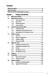
... Audio CODEC 10 x USB 2.0 ports (4 ports at the mid-board, 6 ports at the back panel) ASUS Crash Free BIOS3 ASUS Network iControl ASUS MyLogo 2 ASUS Fan Xpert ASUS UEFI BIOS ASUS Anti-Surge Protection ASUS GPU Boost (continued on the next page) ix Resolution: 2048 x 1536 @75Hz 1 x PCI Express 3.0/2.0 ...or more, Windows® 32-bit operating system may only recognize less than 3GB. P8H61-M LX2 R2.0 specifications summary CPU Chipset Memory Graphics Expansion slots Storage LAN Audio USB ASUS unique features LGA1155 socket for the Memory QVL (Qualified Vendors List) Multi-VGA Output Support...
... Audio CODEC 10 x USB 2.0 ports (4 ports at the mid-board, 6 ports at the back panel) ASUS Crash Free BIOS3 ASUS Network iControl ASUS MyLogo 2 ASUS Fan Xpert ASUS UEFI BIOS ASUS Anti-Surge Protection ASUS GPU Boost (continued on the next page) ix Resolution: 2048 x 1536 @75Hz 1 x PCI Express 3.0/2.0 ...or more, Windows® 32-bit operating system may only recognize less than 3GB. P8H61-M LX2 R2.0 specifications summary CPU Chipset Memory Graphics Expansion slots Storage LAN Audio USB ASUS unique features LGA1155 socket for the Memory QVL (Qualified Vendors List) Multi-VGA Output Support...
P8H61-M LX R2 User's Manual
Page 11
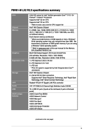
... the items is detached from the wall socket before you install motherboard components or change any motherboard component. Refer to page x for buying an ASUS® P8H61-M LX2 R2.0 Series motherboard! This is a reminder that you should shut down the system and unplug the power cable before removing or plugging in the bag... that came with a standby power LED that lights up to indicate that the power supply is switched off mode. SB_PWR P8H61-M LX2 R2.0 ON OFF Standby Power Powered Off P8H61-M LX2 R2.0 Onboard LED Chapter 1: Product introduction 1-1
... the items is detached from the wall socket before you install motherboard components or change any motherboard component. Refer to page x for buying an ASUS® P8H61-M LX2 R2.0 Series motherboard! This is a reminder that you should shut down the system and unplug the power cable before removing or plugging in the bag... that came with a standby power LED that lights up to indicate that the power supply is switched off mode. SB_PWR P8H61-M LX2 R2.0 ON OFF Standby Power Powered Off P8H61-M LX2 R2.0 Onboard LED Chapter 1: Product introduction 1-1
P8H61-M LX R2 User's Manual
Page 12
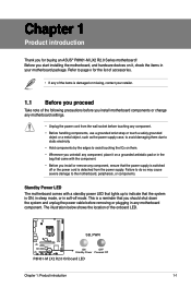
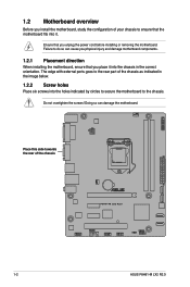
... holes indicated by circles to secure the motherboard to the chassis. The edge with external ports goes to the rear part of the chassis P8H61-M LX2 R2.0 1-2 ASUS P8H61-M LX2 R2.0 Doing so can cause you physical injury and damage motherboard components. 1.2.1 Placement direction When installing the motherboard, ensure that you unplug the power cord...
... holes indicated by circles to secure the motherboard to the chassis. The edge with external ports goes to the rear part of the chassis P8H61-M LX2 R2.0 1-2 ASUS P8H61-M LX2 R2.0 Doing so can cause you physical injury and damage motherboard components. 1.2.1 Placement direction When installing the motherboard, ensure that you unplug the power cord...
P8H61-M LX R2 User's Manual
Page 14
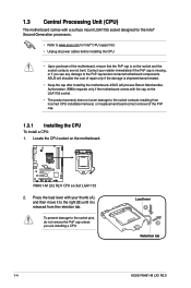
... of repair only if the damage is shipment/transit-related. • Keep the cap after installing the motherboard. P8H61-M LX2 R2.0 P8H61-M LX2 R2.0 CPU socket LGA1155 2. ASUS will process Return Merchandise Authorization (RMA) requests only if the motherboard comes with the cap on the LGA1155 socket....8226; The product warranty does not cover damage to the socket contacts resulting from the retention tab. Load lever A B Retention tab 1-4 ASUS P8H61-M LX2 R2.0 ASUS will shoulder the cost of the PnP cap. 1.3.1 Installing the CPU To install a CPU: 1. Locate the CPU socket on the ...
... of repair only if the damage is shipment/transit-related. • Keep the cap after installing the motherboard. P8H61-M LX2 R2.0 P8H61-M LX2 R2.0 CPU socket LGA1155 2. ASUS will process Return Merchandise Authorization (RMA) requests only if the motherboard comes with the cap on the LGA1155 socket....8226; The product warranty does not cover damage to the socket contacts resulting from the retention tab. Load lever A B Retention tab 1-4 ASUS P8H61-M LX2 R2.0 ASUS will shoulder the cost of the PnP cap. 1.3.1 Installing the CPU To install a CPU: 1. Locate the CPU socket on the ...
P8H61-M LX R2 User's Manual
Page 16
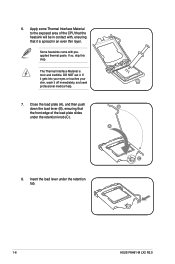
... off immediately, and seek professional medical help. 7. Apply some Thermal Interface Material to the exposed area of the load plate slides under the retention tab. 1-6 ASUS P8H61-M LX2 R2.0 The Thermal Interface Material is spread in contact with preapplied thermal paste.
... off immediately, and seek professional medical help. 7. Apply some Thermal Interface Material to the exposed area of the load plate slides under the retention tab. 1-6 ASUS P8H61-M LX2 R2.0 The Thermal Interface Material is spread in contact with preapplied thermal paste.

P8H61-M LX R2 User's Manual
Page 18
... heatsink and fan To uninstall the CPU heatsink and fan: 1. Hardware monitoring errors can occur if you fail to connect the CPU fan connector! A B A B B A B A 1-8 ASUS P8H61-M LX2 R2.0 Disconnect the CPU fan cable from the motherboard. Connect the CPU fan cable to disengage the heatsink and fan assembly from the connector on the...
... heatsink and fan To uninstall the CPU heatsink and fan: 1. Hardware monitoring errors can occur if you fail to connect the CPU fan connector! A B A B B A B A 1-8 ASUS P8H61-M LX2 R2.0 Disconnect the CPU fan cable from the motherboard. Connect the CPU fan cable to disengage the heatsink and fan assembly from the connector on the...
P8H61-M LX R2 User's Manual
Page 19
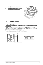
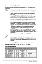
... memory 1.4.1 Overview The motherboard comes with less power consumption. The figure illustrates the location of the DDR3 DIMM sockets: DIMM_A1 DIMM_B1 P8H61-M LX2 R2.0 Channel Channel A Channel B Sockets DIMM_A1 DIMM_B1 P8H61-M LX2 R2.0 240-pin DDR3 DIMM sockets Chapter 1: Product introduction 1-9 DDR3 modules are developed for better performance with two Double Data Rate 3 (DDR3...
... memory 1.4.1 Overview The motherboard comes with less power consumption. The figure illustrates the location of the DDR3 DIMM sockets: DIMM_A1 DIMM_B1 P8H61-M LX2 R2.0 Channel Channel A Channel B Sockets DIMM_A1 DIMM_B1 P8H61-M LX2 R2.0 240-pin DDR3 DIMM sockets Chapter 1: Product introduction 1-9 DDR3 modules are developed for better performance with two Double Data Rate 3 (DDR3...
P8H61-M LX R2 User's Manual
Page 20
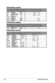
...7 1.5V KINGSTON KVR1066D3N7/4G 4GB DS Hynix H5TQ2G83AFR 7 1.5V Kingtiger 2GB DIMM PC3-8500 2GB DS Hynix H5TQ1G83AFP G7C - - 1-10 ASUS P8H61-M LX2 R2.0 Use a maximum of 3GB system memory if you do any of 512Mb (64MB) chips or less. • The default memory operation ...depend on the CPU's capabilities and other installed devices. • This motherboard does not support DIMMs made up of the following: - P8H61-M LX2 R2.0 Motherboard Qualified Vendors Lists (QVL) DDR3-1066 MHz capability Vendors Part No. Crucial CT12872BA1067.9FF 1GB SS Micron 9HF22D9KPT(ECC) 7 -...
...7 1.5V KINGSTON KVR1066D3N7/4G 4GB DS Hynix H5TQ2G83AFR 7 1.5V Kingtiger 2GB DIMM PC3-8500 2GB DS Hynix H5TQ1G83AFP G7C - - 1-10 ASUS P8H61-M LX2 R2.0 Use a maximum of 3GB system memory if you do any of 512Mb (64MB) chips or less. • The default memory operation ...depend on the CPU's capabilities and other installed devices. • This motherboard does not support DIMMs made up of the following: - P8H61-M LX2 R2.0 Motherboard Qualified Vendors Lists (QVL) DDR3-1066 MHz capability Vendors Part No. Crucial CT12872BA1067.9FF 1GB SS Micron 9HF22D9KPT(ECC) 7 -...
P8H61-M LX R2 User's Manual
Page 26
...-9-27 - 10-11-10-30 - - - 9 - 9 - 9-11-9-27 Voltage 1.65V 1.65V 1.65V 1.65V 1.8V 1.65V 1.65V 1.65V 1.65V DIMM socket support (optional) 1DIMM 2DIMMs 1-16 ASUS P8H61-M LX2 R2.0 DDR3-2200 MHz capability Vendors Part No. SS/DS Chip Brand Chip NO. Size SS/ Chip Chip DS Brand NO. Timing CMGTX8(XMP) 8GB (2GBx...
...-9-27 - 10-11-10-30 - - - 9 - 9 - 9-11-9-27 Voltage 1.65V 1.65V 1.65V 1.65V 1.8V 1.65V 1.65V 1.65V 1.65V DIMM socket support (optional) 1DIMM 2DIMMs 1-16 ASUS P8H61-M LX2 R2.0 DDR3-2200 MHz capability Vendors Part No. SS/DS Chip Brand Chip NO. Size SS/ Chip Chip DS Brand NO. Timing CMGTX8(XMP) 8GB (2GBx...
P8H61-M LX R2 User's Manual
Page 28
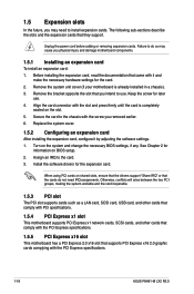
... other cards that comply with it by adjusting the software settings. 1. Failure to do not need to the chassis with the PCI Express specifications. 1-18 ASUS P8H61-M LX2 R2.0 Turn on the slot. 5. Before installing the expansion card, read the documentation that came with the PCI Express specifications. 1.5.5 PCI Express x16 slot This...
... other cards that comply with it by adjusting the software settings. 1. Failure to do not need to the chassis with the PCI Express specifications. 1-18 ASUS P8H61-M LX2 R2.0 Turn on the slot. 5. Before installing the expansion card, read the documentation that came with the PCI Express specifications. 1.5.5 PCI Express x16 slot This...
P8H61-M LX R2 User's Manual
Page 29
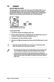
... and reboot the system, then the BIOS automatically resets parameter settings to re-enter data. For system failure due to pins 2-3. P8H61-M LX2 R2.0 CLRTC 12 23 Normal (Default) Clear RTC P8H61-M LX2 R2.0 Clear RTC RAM To erase the RTC RAM: 1. The onboard button cell battery powers the RAM data in CMOS. Keep...
... and reboot the system, then the BIOS automatically resets parameter settings to re-enter data. For system failure due to pins 2-3. P8H61-M LX2 R2.0 CLRTC 12 23 Normal (Default) Clear RTC P8H61-M LX2 R2.0 Clear RTC RAM To erase the RTC RAM: 1. The onboard button cell battery powers the RAM data in CMOS. Keep...
P8H61-M LX R2 User's Manual
Page 30
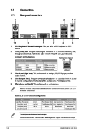
... port LED indications. Refer to the table below for a PS/2 keyboard or PS/2 mouse. 2. Microphone port (pink). Refer to support 8-channel audio output. 1-20 ASUS P8H61-M LX2 R2.0 LAN port LED indications Activity/Link LED Status Description OFF No link ORANGE Linked BLINKING Data activity Speed LED Status OFF ORANGE GREEN Description 10Mbps...
... port LED indications. Refer to the table below for a PS/2 keyboard or PS/2 mouse. 2. Microphone port (pink). Refer to support 8-channel audio output. 1-20 ASUS P8H61-M LX2 R2.0 LAN port LED indications Activity/Link LED Status Description OFF No link ORANGE Linked BLINKING Data activity Speed LED Status OFF ORANGE GREEN Description 10Mbps...
P8H61-M LX R2 User's Manual
Page 31
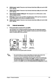
... AGND NC NC NC AAFP PIN 1 PIN 1 MIC2 MICPWR Line out_R NC Line out_L PORT1 L PORT1 R PORT2 R SENSE_SEND PORT2 L P8H61-M LX2 R2.0 HD-audio-compliant Legacy AC'97 pin definition compliant definition P8H61-M LX2 R2.0 Front panel audio connector • We recommend that supports either HD Audio or legacy AC`97 audio standard. 6. These...
... AGND NC NC NC AAFP PIN 1 PIN 1 MIC2 MICPWR Line out_R NC Line out_L PORT1 L PORT1 R PORT2 R SENSE_SEND PORT2 L P8H61-M LX2 R2.0 HD-audio-compliant Legacy AC'97 pin definition compliant definition P8H61-M LX2 R2.0 Front panel audio connector • We recommend that supports either HD Audio or legacy AC`97 audio standard. 6. These...
P8H61-M LX R2 User's Manual
Page 32
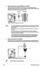
...PSCalculator.aspx?SLanguage=en-us for ATX power supply plugs. Serial port connector (10-1 pin COM1) This connector is purchased separately. 1-22 ASUS P8H61-M LX2 R2.0 ATX power connectors (24-pin EATXPWR, 4-pin ATX12V) These connectors are designed to connect the 4-pin ATX +12V power plug. The ... DTR DSR CTS PIN 1 DCD TXD GND RTS RI P8H61-M LX2 R2.0 P8H61-M LX2 R2.0 Serial port (COM1) connector The COM module is for your system, refer to a slot opening at http://support.asus. EATX12V EATXPWR +12V DC +12V DC P8H61-M LX2 R2.0 GND GND +3 Volts +12 Volts +12 Volts +...
...PSCalculator.aspx?SLanguage=en-us for ATX power supply plugs. Serial port connector (10-1 pin COM1) This connector is purchased separately. 1-22 ASUS P8H61-M LX2 R2.0 ATX power connectors (24-pin EATXPWR, 4-pin ATX12V) These connectors are designed to connect the 4-pin ATX +12V power plug. The ... DTR DSR CTS PIN 1 DCD TXD GND RTS RI P8H61-M LX2 R2.0 P8H61-M LX2 R2.0 Serial port (COM1) connector The COM module is for your system, refer to a slot opening at http://support.asus. EATX12V EATXPWR +12V DC +12V DC P8H61-M LX2 R2.0 GND GND +3 Volts +12 Volts +12 Volts +...
P8H61-M LX R2 User's Manual
Page 33
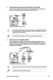
...may damage the motherboard components. USB910 USB78 USB+5V USB_P10USB_P10+ GND NC USB+5V USB_P8USB_P8+ GND NC P8H61-M LX2 R2.0 PIN 1 PIN 1 USB+5V USB_P9USB_P9+ GND USB+5V USB_P7USB_P7+ GND P8H61-M LX2 R2.0 USB2.0 connectors Never connect a 1394 cable to the fan connectors. These are for USB 2.0 ports...connector supports a CPU fan of the system chassis. CPU_FAN CPU FAN PWM CPU FAN IN CPU FAN PWR GND P8H61-M LX2 R2.0 CHA_FAN GND +12V Rotation P8H61-M LX2 R2.0 CPU connectors Do not forget to connect the fan cables to the USB connectors. Doing so will damage the motherboard...
...may damage the motherboard components. USB910 USB78 USB+5V USB_P10USB_P10+ GND NC USB+5V USB_P8USB_P8+ GND NC P8H61-M LX2 R2.0 PIN 1 PIN 1 USB+5V USB_P9USB_P9+ GND USB+5V USB_P7USB_P7+ GND P8H61-M LX2 R2.0 USB2.0 connectors Never connect a 1394 cable to the fan connectors. These are for USB 2.0 ports...connector supports a CPU fan of the system chassis. CPU_FAN CPU FAN PWM CPU FAN IN CPU FAN PWR GND P8H61-M LX2 R2.0 CHA_FAN GND +12V Rotation P8H61-M LX2 R2.0 CPU connectors Do not forget to connect the fan cables to the USB connectors. Doing so will damage the motherboard...

P8H61-M LX R2 User's Manual
Page 34
...RSATA_TXP3 GND GND RSATA_RXP4 RSATA_RXN4 GND RSATA_TXN4 RSATA_TXP4 GND P8H61-M LX2 R2.0 SATA3G_1 GND RSATA_TXP1 RSATA_TXN1 GND RSATA_RXN1 RSATA_RXP1 GND SATA3G_2 GND RSATA_TXP2 RSATA_TXN2 GND RSATA_RXN2 RSATA_RXP2 GND SATA3G_3 SATA3G_4 P8H61-M LX2 R2.0 SATA connectors • You must install Windows&#... is for details. 7. Please use IDE Mode on Windows® XP. • [IDE] is purchased separately. 1-24 ASUS P8H61-M LX2 R2.0 See section 2.5.4 SATA Configuration for an additional Sony/Philips Digital Interface (S/PDIF) port. Digital audio connector (4-1 pin SPDIF_OUT) ...
...RSATA_TXP3 GND GND RSATA_RXP4 RSATA_RXN4 GND RSATA_TXN4 RSATA_TXP4 GND P8H61-M LX2 R2.0 SATA3G_1 GND RSATA_TXP1 RSATA_TXN1 GND RSATA_RXN1 RSATA_RXP1 GND SATA3G_2 GND RSATA_TXP2 RSATA_TXN2 GND RSATA_RXN2 RSATA_RXP2 GND SATA3G_3 SATA3G_4 P8H61-M LX2 R2.0 SATA connectors • You must install Windows&#... is for details. 7. Please use IDE Mode on Windows® XP. • [IDE] is purchased separately. 1-24 ASUS P8H61-M LX2 R2.0 See section 2.5.4 SATA Configuration for an additional Sony/Philips Digital Interface (S/PDIF) port. Digital audio connector (4-1 pin SPDIF_OUT) ...
P8H61-M LX R2 User's Manual
Page 35
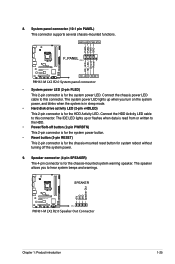
...This 2-pin connector is for the chassis-mounted reset button for the system power LED. Ground Reset 8. PWR LED PWR BTN F_PANEL PIN 1 P8H61-M LX2 R2.0 HD_LED RESET P8H61-M LX2 R2.0 System panel connector • System power LED (2-pin PLED) This 2-pin connector is for system reboot without turning off button (2-pin PWRBTN...The IDE LED lights up when you to the HDD. • Power/Soft-off the system power. 9. PLED+ PLEDPWR GND HD_LED+ HD_LED- SPEAKER P8H61-M LX2 R2.0 PIN 1 P8H61-M LX2 R2.0 Speaker Out Connector +5V GND GND Speaker Out Chapter 1: Product introduction 1-25
...This 2-pin connector is for the chassis-mounted reset button for the system power LED. Ground Reset 8. PWR LED PWR BTN F_PANEL PIN 1 P8H61-M LX2 R2.0 HD_LED RESET P8H61-M LX2 R2.0 System panel connector • System power LED (2-pin PLED) This 2-pin connector is for system reboot without turning off button (2-pin PWRBTN...The IDE LED lights up when you to the HDD. • Power/Soft-off the system power. 9. PLED+ PLEDPWR GND HD_LED+ HD_LED- SPEAKER P8H61-M LX2 R2.0 PIN 1 P8H61-M LX2 R2.0 Speaker Out Connector +5V GND GND Speaker Out Chapter 1: Product introduction 1-25
P8H61-M LX R2 User's Manual
Page 36
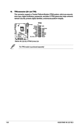
P8H61-M LX2 R2.0 TPM PIN 1 PCICLK FRAME PCIRST# LAD3 +3V LAD0 SMBSCL +3VSB GND SB_SUS_STAT GND PWROWN LAD2 LAD1 GND SMBSDA SERIRQ GPIO RESET P8H61-M LX2 R2.0 TPM Connector The TPM module is purchased separately! 1-26 ASUS P8H61-M LX2 R2.0 TPM connector (20-1 pin TPM) This connector supports a Trusted Platform Module (TPM) system, which can securely store keys, digital certificates, passwords, and data. 10. A TPM system also helps enhance network security, protects digital identities, and ensures platform integrity.
P8H61-M LX2 R2.0 TPM PIN 1 PCICLK FRAME PCIRST# LAD3 +3V LAD0 SMBSCL +3VSB GND SB_SUS_STAT GND PWROWN LAD2 LAD1 GND SMBSDA SERIRQ GPIO RESET P8H61-M LX2 R2.0 TPM Connector The TPM module is purchased separately! 1-26 ASUS P8H61-M LX2 R2.0 TPM connector (20-1 pin TPM) This connector supports a Trusted Platform Module (TPM) system, which can securely store keys, digital certificates, passwords, and data. 10. A TPM system also helps enhance network security, protects digital identities, and ensures platform integrity.


