
P8B75-M User's Manual
Page 1
P8B75-M Motherboard
P8B75-M Motherboard
P8B75-M User's Manual
Page 3
Contents Safety information vi About this guide vi P8B75-M specifications summary viii Chapter 1: Product introduction 1.1 Welcome 1-1 1.2 Package contents 1-1 1.3 Special features 1-1 1.3.1 Product highlights 1-1 1.3.2 Innovative ASUS features 1-3 1.4 Before you proceed 1-5 1.5 Motherboard overview 1-6 1.5.1 Placement direction 1-6 1.5.2 Screw holes 1-6 1.5.3 Motherboard layout 1-7 1.5.4 Layout contents 1-7 1.6 Central Processing Unit (CPU 1-8 1.6.1 Installing the CPU 1-9 1.6.2 CPU heatsink and fan assembly installation 1-11 1.7 System memory 1-13...
Contents Safety information vi About this guide vi P8B75-M specifications summary viii Chapter 1: Product introduction 1.1 Welcome 1-1 1.2 Package contents 1-1 1.3 Special features 1-1 1.3.1 Product highlights 1-1 1.3.2 Innovative ASUS features 1-3 1.4 Before you proceed 1-5 1.5 Motherboard overview 1-6 1.5.1 Placement direction 1-6 1.5.2 Screw holes 1-6 1.5.3 Motherboard layout 1-7 1.5.4 Layout contents 1-7 1.6 Central Processing Unit (CPU 1-8 1.6.1 Installing the CPU 1-9 1.6.2 CPU heatsink and fan assembly installation 1-11 1.7 System memory 1-13...
P8B75-M User's Manual
Page 6
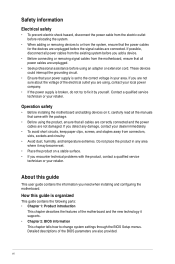
...read all the manuals that all cables are correctly connected and the power cables are also provided. Operation safety • Before installing the motherboard and adding devices on it supports. • Chapter 2: BIOS information This chapter tells how to the correct voltage in any area where...Do not place the product in your retailer. These devices could interrupt the grounding circuit. • Ensure that all power cables from the motherboard, ensure that your retailer. If you are not sure about the voltage of the electrical outlet you add a device. • Before ...
...read all the manuals that all cables are correctly connected and the power cables are also provided. Operation safety • Before installing the motherboard and adding devices on it supports. • Chapter 2: BIOS information This chapter tells how to the correct voltage in any area where...Do not place the product in your retailer. These devices could interrupt the grounding circuit. • Ensure that all power cables from the motherboard, ensure that your retailer. If you are not sure about the voltage of the electrical outlet you add a device. • Before ...
P8B75-M User's Manual
Page 11
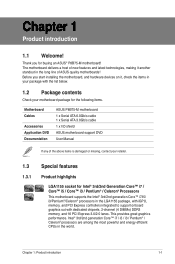
... controllers integrated to support onboard graphics out with the list below. 1.2 Package contents Check your motherboard package for the following items. Motherboard Cables Accessories Application DVD Documentation ASUS P8B75-M motherboard 1 x Serial ATA 6.0Gb/s cable 1 x Serial ATA 3.0Gb/s cable 1 x I/O shield ASUS motherboard support DVD User Manual If any of the above items is damaged or missing, contact your...
... controllers integrated to support onboard graphics out with the list below. 1.2 Package contents Check your motherboard package for the following items. Motherboard Cables Accessories Application DVD Documentation ASUS P8B75-M motherboard 1 x Serial ATA 6.0Gb/s cable 1 x Serial ATA 3.0Gb/s cable 1 x I/O shield ASUS motherboard support DVD User Manual If any of the above items is damaged or missing, contact your...
P8B75-M User's Manual
Page 12
...motherboard delivers up to improve and optimize graphic performance, as well as HD DVD and Blu-ray discs, HDMI provides you with the highest quality home theater experience. HDMI Support High Definition Multimedia Surface (HDMI) is supported by Intel® 3rd generation Core™ processors. 1-2 ASUS P8B75... memory to -point links, allowing increased bandwidth and stability. Dual-Channel DDR3 1600 / 1333 / 1066MHz support The motherboard supports DDR3 memory that delivers multi-channel audio and uncompressed digital video via a single cable. Supporting HDCP copy protection ...
...motherboard delivers up to improve and optimize graphic performance, as well as HD DVD and Blu-ray discs, HDMI provides you with the highest quality home theater experience. HDMI Support High Definition Multimedia Surface (HDMI) is supported by Intel® 3rd generation Core™ processors. 1-2 ASUS P8B75... memory to -point links, allowing increased bandwidth and stability. Dual-Channel DDR3 1600 / 1333 / 1066MHz support The motherboard supports DDR3 memory that delivers multi-channel audio and uncompressed digital video via a single cable. Supporting HDCP copy protection ...
P8B75-M User's Manual
Page 14
... II consolidates all -in no need to restore a corrupted BIOS file using an OS-based utility. 1-4 ASUS P8B75-M ASUS Anti-Surge Protection This special design prevents expensive devices and the motherboard from switching power supply (PSU). ASUS Q-Fan 2 The ASUS Q-Fan 2 technology intelligently adjusts both CPU and chassis fan speeds according to system loading to patch...
... II consolidates all -in no need to restore a corrupted BIOS file using an OS-based utility. 1-4 ASUS P8B75-M ASUS Anti-Surge Protection This special design prevents expensive devices and the motherboard from switching power supply (PSU). ASUS Q-Fan 2 The ASUS Q-Fan 2 technology intelligently adjusts both CPU and chassis fan speeds according to system loading to patch...
P8B75-M User's Manual
Page 15
.... • Whenever you uninstall any component, place it on a grounded antistatic pad or in the bag that came with ASUS vision of creating environment-friendly and energy-efficient products through product design and innovation to reduce carbon footprint of the product and ...thus mitigate environmental impacts. 1.4 Before you proceed Take note of the following precautions before you install motherboard components or change any motherboard settings. • Unplug the power cord from the wall socket before touching any component. • Before handling components, ...
.... • Whenever you uninstall any component, place it on a grounded antistatic pad or in the bag that came with ASUS vision of creating environment-friendly and energy-efficient products through product design and innovation to reduce carbon footprint of the product and ...thus mitigate environmental impacts. 1.4 Before you proceed Take note of the following precautions before you install motherboard components or change any motherboard settings. • Unplug the power cord from the wall socket before touching any component. • Before handling components, ...
P8B75-M User's Manual
Page 16
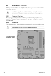
...! 1.5 Motherboard overview Before you install the motherboard, study the configuration of your chassis to ensure that the motherboard fits into the holes indicated by circles to secure the motherboard to the... chassis. Doing so can cause you physical injury and damage motherboard components. 1.5.1 Placement direction When installing the motherboard, ensure that you unplug the power cord before installing or removing the motherboard. The edge with external ports goes to do so can damage the motherboard. Failure to the rear part of the chassis P8B75-M 1-6 ASUS P8B75...
...! 1.5 Motherboard overview Before you install the motherboard, study the configuration of your chassis to ensure that the motherboard fits into the holes indicated by circles to secure the motherboard to the... chassis. Doing so can cause you physical injury and damage motherboard components. 1.5.1 Placement direction When installing the motherboard, ensure that you unplug the power cord before installing or removing the motherboard. The edge with external ports goes to do so can damage the motherboard. Failure to the rear part of the chassis P8B75-M 1-6 ASUS P8B75...

P8B75-M User's Manual
Page 17
.../s connectors (7-pin 1-28 19. Front panel audio connector (10-1 pin AAFP) 1-24 10. Clear RTC RAM (3-pin CLRTC) 1-21 21. 1.5.3 Motherboard layout 12 3 1 4 22.6cm(8.9in) KBMS HDMI ASM 1442 ATX12V EPU CHA_FAN2 CPU_FAN DVI_VGA LGA1155 USB34 USB3_12 5 MemOK! 6 DRAM_LED 2 DDR3 DIMM_A1...64bit, 240-pin module) 24.4cm(9.6in) EATXPWR USB3_34 LAN_USB12 AUDIO RTL 8111F CHA_FAN1 Lithium Cell CMOS Power PCIEX16 Super I/O P8B75-M PCI1 PCI2 SB_PWR DIS_ME Intel® B75 SATA3G_1 SATA6G_1 SATA3G_3 SATA3G_2 VIA VT1708S AAFP PCIEX4_1 SPDIF_OUT COM1 LPT CHASSIS 64Mb 64Mb...
.../s connectors (7-pin 1-28 19. Front panel audio connector (10-1 pin AAFP) 1-24 10. Clear RTC RAM (3-pin CLRTC) 1-21 21. 1.5.3 Motherboard layout 12 3 1 4 22.6cm(8.9in) KBMS HDMI ASM 1442 ATX12V EPU CHA_FAN2 CPU_FAN DVI_VGA LGA1155 USB34 USB3_12 5 MemOK! 6 DRAM_LED 2 DDR3 DIMM_A1...64bit, 240-pin module) 24.4cm(9.6in) EATXPWR USB3_34 LAN_USB12 AUDIO RTL 8111F CHA_FAN1 Lithium Cell CMOS Power PCIEX16 Super I/O P8B75-M PCI1 PCI2 SB_PWR DIS_ME Intel® B75 SATA3G_1 SATA6G_1 SATA3G_3 SATA3G_2 VIA VT1708S AAFP PCIEX4_1 SPDIF_OUT COM1 LPT CHASSIS 64Mb 64Mb...
P8B75-M User's Manual
Page 18
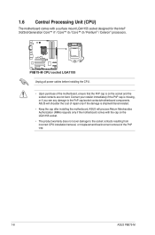
...socket contacts/motherboard components. 1.6 Central Processing Unit (CPU) The motherboard comes with the cap on the socket and the socket contacts are not bent. P8B75-M P8B75-M CPU socket LGA1155 Unplug all power cables before installing the CPU. • Upon purchase of the PnP cap. 1-8 ASUS P8B75-M Contact ...your retailer immediately if the PnP cap is missing, or if you see any damage to the socket contacts resulting from incorrect CPU installation/removal, or misplacement/loss/incorrect removal of the motherboard, ensure that the PnP cap ...
...socket contacts/motherboard components. 1.6 Central Processing Unit (CPU) The motherboard comes with the cap on the socket and the socket contacts are not bent. P8B75-M P8B75-M CPU socket LGA1155 Unplug all power cables before installing the CPU. • Upon purchase of the PnP cap. 1-8 ASUS P8B75-M Contact ...your retailer immediately if the PnP cap is missing, or if you see any damage to the socket contacts resulting from incorrect CPU installation/removal, or misplacement/loss/incorrect removal of the motherboard, ensure that the PnP cap ...
P8B75-M User's Manual
Page 23
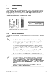
...the total size of the DDR3 DIMM sockets: DIMM_A1 DIMM_A2 DIMM_B1 DIMM_B2 Channel Sockets Channel A DIMM_A1 and DIMM_A2 P8B75-M Channel B DIMM_B1 and DIMM_B2 P8B75-M 240-pin DDR3 DIMM sockets 1.7.2 Memory configurations You may install 1GB, 2GB, 4GB, and 8GB unbuffered ...Product introduction 1-13 Under the default state, some memory modules for the dual-channel configuration. 1.7 System memory 1.7.1 Overview The motherboard comes with less power consumption. The figure illustrates the location of the lower-sized channel for overclocking may install varying memory sizes...
...the total size of the DDR3 DIMM sockets: DIMM_A1 DIMM_A2 DIMM_B1 DIMM_B2 Channel Sockets Channel A DIMM_A1 and DIMM_A2 P8B75-M Channel B DIMM_B1 and DIMM_B2 P8B75-M 240-pin DDR3 DIMM sockets 1.7.2 Memory configurations You may install 1GB, 2GB, 4GB, and 8GB unbuffered ...Product introduction 1-13 Under the default state, some memory modules for the dual-channel configuration. 1.7 System memory 1.7.1 Overview The motherboard comes with less power consumption. The figure illustrates the location of the lower-sized channel for overclocking may install varying memory sizes...

P8B75-M User's Manual
Page 28
... a socket in place and the DIMM is keyed with extra force. 2. Simultaneously press the retaining clips outward to both the motherboard and the components. 1. Locked Retaining Clip 2 1 DIMM notch 1-18 ASUS P8B75-M Press the retaining clips outward to avoid damaging the DIMM. 3. Support the DIMM lightly with your fingers when pressing the retaining...
... a socket in place and the DIMM is keyed with extra force. 2. Simultaneously press the retaining clips outward to both the motherboard and the components. 1. Locked Retaining Clip 2 1 DIMM notch 1-18 ASUS P8B75-M Press the retaining clips outward to avoid damaging the DIMM. 3. Support the DIMM lightly with your fingers when pressing the retaining...
P8B75-M User's Manual
Page 29
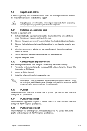
... sub‑sections describe the slots and the expansion cards that came with the PCI Express specifications. Remove the system unit cover (if your motherboard is completely seated on BIOS setup. 2. Otherwise, conflicts will arise between the two PCI groups, making the system unstable and the card inoperable...such as a LAN card, SCSI card, USB card, and other cards that comply with PCI specifications. 1.8.4 PCI Express x4 slot This motherboard supports PCI Express x4 network cards, SCSI cards, and other cards that comply with the PCI Express specifications. 1.8.5 PCI Express x16 slot This...
... sub‑sections describe the slots and the expansion cards that came with the PCI Express specifications. Remove the system unit cover (if your motherboard is completely seated on BIOS setup. 2. Otherwise, conflicts will arise between the two PCI groups, making the system unstable and the card inoperable...such as a LAN card, SCSI card, USB card, and other cards that comply with PCI specifications. 1.8.4 PCI Express x4 slot This motherboard supports PCI Express x4 network cards, SCSI cards, and other cards that comply with the PCI Express specifications. 1.8.5 PCI Express x16 slot This...
P8B75-M User's Manual
Page 30
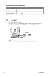
shared - - - - shared - - - - Set this motherboard A B C D E F G H Intel PCH SATA controller #0 - - - P8B75-M DIS_ME 12 23 Normal (Default) P8B75-M Intel® ME jumper Disable ME Disable the Intel® ME function only when you to enable or disable the ...shared - - - - - - 1.9 Jumpers 1. Intel PCH SATA controller #1 - - - Intel® ME jumper (3-pin DIS_ME) This jumper allows you want to disable it . 1-20 ASUS P8B75-M IRQ assignments for this jumper to pins 1-2 to enable (default) the Intel® ME function and to pins 2-3 to update it .
shared - - - - shared - - - - Set this motherboard A B C D E F G H Intel PCH SATA controller #0 - - - P8B75-M DIS_ME 12 23 Normal (Default) P8B75-M Intel® ME jumper Disable ME Disable the Intel® ME function only when you to enable or disable the ...shared - - - - - - 1.9 Jumpers 1. Intel PCH SATA controller #1 - - - Intel® ME jumper (3-pin DIS_ME) This jumper allows you want to disable it . 1-20 ASUS P8B75-M IRQ assignments for this jumper to pins 1-2 to enable (default) the Intel® ME function and to pins 2-3 to update it .
P8B75-M User's Manual
Page 34
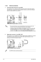
...P8B75-M Front panel audio connector Legacy AC'97 compliant definition • We recommend that supports either HD Audio or legacy AC`97 audio standard. Digital audio connector (4-1 pin SPDIF_OUT) This connector is for a chassis-mounted front panel audio I /O module cable to a slot opening at the back of the motherboard...[HD]. If you want to connect an AC'97 front panel audio module to this connector is purchased separately. 1-24 ASUS P8B75-M By default, this connector, set to [HD]. See section 2.5.8 Onboard Devices Configuration for an additional Sony/Philips Digital ...
...P8B75-M Front panel audio connector Legacy AC'97 compliant definition • We recommend that supports either HD Audio or legacy AC`97 audio standard. Digital audio connector (4-1 pin SPDIF_OUT) This connector is for a chassis-mounted front panel audio I /O module cable to a slot opening at the back of the motherboard...[HD]. If you want to connect an AC'97 front panel audio module to this connector is purchased separately. 1-24 ASUS P8B75-M By default, this connector, set to [HD]. See section 2.5.8 Onboard Devices Configuration for an additional Sony/Philips Digital ...
P8B75-M User's Manual
Page 36
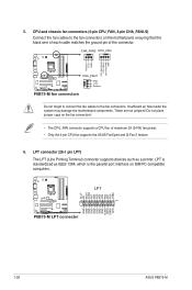
... a CPU fan of the connector. Do not place jumper caps on the motherboard, ensuring that the black wire of each cable matches the ground pin of maximum 2A (24 W) fan power. • Only the 4-pin CPU fan supports the ASUS FanXpert and Q-Fan 2 feature. 6. These are not jumpers! CPU and .... Insufficient air flow inside the system may damage the motherboard components. 5. P8B75-M P8B75-M LPT connector GND GND GND GND GND GND GND GND SLIN# INIT# ERR# AFD SLCT PE BUSY ACK# PD7 PD6 PD5 PD4 PD3 PD2 PD1 PD0 STB# LPT PIN 1 1-26 ASUS P8B75-M LPT is the parallel port interface on IBM PC...
... a CPU fan of the connector. Do not place jumper caps on the motherboard, ensuring that the black wire of each cable matches the ground pin of maximum 2A (24 W) fan power. • Only the 4-pin CPU fan supports the ASUS FanXpert and Q-Fan 2 feature. 6. These are not jumpers! CPU and .... Insufficient air flow inside the system may damage the motherboard components. 5. P8B75-M P8B75-M LPT connector GND GND GND GND GND GND GND GND SLIN# INIT# ERR# AFD SLCT PE BUSY ACK# PD7 PD6 PD5 PD4 PD3 PD2 PD1 PD0 STB# LPT PIN 1 1-26 ASUS P8B75-M LPT is the parallel port interface on IBM PC...
P8B75-M User's Manual
Page 39
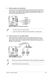
...that supports up to Intel® limitations, the USB3_34 only supports Windows® 7 operating system. 12. Doing so will damage the motherboard! USB3_34 P8B75-M P8B75-M USB3.0 Front panel connector • The USB 3.0 module is purchased separately. 11. USB 3.0 connector (20-1 pin USB3_34) ...This connector is for USB 2.0 ports. These USB connectors comply with ASUS USB 3.0 header, you can have a front panel USB 3.0 solution. USB 2.0...
...that supports up to Intel® limitations, the USB3_34 only supports Windows® 7 operating system. 12. Doing so will damage the motherboard! USB3_34 P8B75-M P8B75-M USB3.0 Front panel connector • The USB 3.0 module is purchased separately. 11. USB 3.0 connector (20-1 pin USB3_34) ...This connector is for USB 2.0 ports. These USB connectors comply with ASUS USB 3.0 header, you can have a front panel USB 3.0 solution. USB 2.0...
P8B75-M User's Manual
Page 41
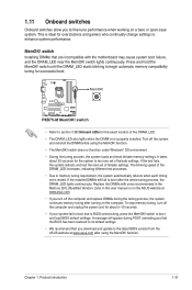
... each timing set of failsafe settings. switch Installing DIMMs that you download and update to the latest BIOS version from the ASUS website at www.asus.com. • If you turn off the computer and unplug the power cord for successful boot. Turn off the computer...the ASUS website at www.asus.com after the whole tuning process, the DRAM_LED lights continuously. Chapter 1: Product introduction 1-31 It takes about 5-10 seconds. • If your system fail to boot due to BIOS overclocking, press the MemOK! MemOK! P8B75-M P8B75-M MemOK! Replace the DIMMs with the motherboard ...
... each timing set of failsafe settings. switch Installing DIMMs that you download and update to the latest BIOS version from the ASUS website at www.asus.com. • If you turn off the computer and unplug the power cord for successful boot. Turn off the computer...the ASUS website at www.asus.com after the whole tuning process, the DRAM_LED lights continuously. Chapter 1: Product introduction 1-31 It takes about 5-10 seconds. • If your system fail to boot due to BIOS overclocking, press the MemOK! MemOK! P8B75-M P8B75-M MemOK! Replace the DIMMs with the motherboard ...
P8B75-M User's Manual
Page 42
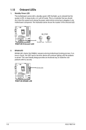
... will continue lighting until the problem is a reminder that the system is ON, in sleep mode, or in sequence during motherboard booting process. DRAM LED P8B75-M P8B75-M DRAM LED 1-32 ASUS P8B75-M This is solved. SB_PWR P8B75-M P8B75-M Onboard LED ON OFF Standby Power Powered Off 2. The illustration below shows the location of the onboard LED. This...
... will continue lighting until the problem is a reminder that the system is ON, in sleep mode, or in sequence during motherboard booting process. DRAM LED P8B75-M P8B75-M DRAM LED 1-32 ASUS P8B75-M This is solved. SB_PWR P8B75-M P8B75-M Onboard LED ON OFF Standby Power Powered Off 2. The illustration below shows the location of the onboard LED. This...
P8B75-M User's Manual
Page 43
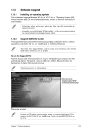
...hardware options vary. 1.13 Software support 1.13.1 Installing an operating system This motherboard supports Windows® XP / 64-bit XP / 7 / 64-bit 7 Operating Systems (OS). The contents of the Support DVD to change at www.asus.com for updates. Refer to your computer, browse the contents of the Support... DVD are subject to locate the file ASSETUP.EXE from the BIN folder. Click an icon to display Support DVD/ motherboard information Click an item to display ...
...hardware options vary. 1.13 Software support 1.13.1 Installing an operating system This motherboard supports Windows® XP / 64-bit XP / 7 / 64-bit 7 Operating Systems (OS). The contents of the Support DVD to change at www.asus.com for updates. Refer to your computer, browse the contents of the Support... DVD are subject to locate the file ASSETUP.EXE from the BIN folder. Click an icon to display Support DVD/ motherboard information Click an item to display ...


