User Guide
Page 15
...1.1 Welcome! Accessories IO shield 1 Plate for LGA1155 1 1 1 Application CD Support CD 1 1 Documentation User Guide 1 1 Packing Qty. 3pcs per carton 10pcs per carton If any of ASUS quality motherboards! Before you for the following items. SATA 6G cable Standard Gift Box Pack Standard Bulk Pack 2 - Thank you start installing the motherboard, and..., making it , check the items in the long line of the above items is damaged or missing, contact your motherboard package for buying an ASUS® P8B-M motherboard! Cables SATA 3G cable 4 - ASUS P8B-M 1-3
...1.1 Welcome! Accessories IO shield 1 Plate for LGA1155 1 1 1 Application CD Support CD 1 1 Documentation User Guide 1 1 Packing Qty. 3pcs per carton 10pcs per carton If any of ASUS quality motherboards! Before you for the following items. SATA 6G cable Standard Gift Box Pack Standard Bulk Pack 2 - Thank you start installing the motherboard, and..., making it , check the items in the long line of the above items is damaged or missing, contact your motherboard package for buying an ASUS® P8B-M motherboard! Cables SATA 3G cable 4 - ASUS P8B-M 1-3
User Guide
Page 17
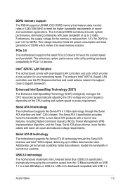
... Intel SpeedStep Technology (EIST) intelligently manages the CPU resources by automatically adjusting the CPU voltage and core frequency depending on USB 2.0. ASUS P8B-M 1-5 The Serial ATA II specification provides twice the bandwidth of the current Serial ATA products with a host of server and workstation...Gigabit LAN controllers use the PCI Express interface and could achieve network throughput close to PCIe 1.0 devices. DDR3 memory support The P8B-M supports UDIMM, ECC DDR3 memory that features data transfer rates of 1333/1066 MHZ to meet the higher bandwidth requirements of...
... Intel SpeedStep Technology (EIST) intelligently manages the CPU resources by automatically adjusting the CPU voltage and core frequency depending on USB 2.0. ASUS P8B-M 1-5 The Serial ATA II specification provides twice the bandwidth of the current Serial ATA products with a host of server and workstation...Gigabit LAN controllers use the PCI Express interface and could achieve network throughput close to PCIe 1.0 devices. DDR3 memory support The P8B-M supports UDIMM, ECC DDR3 memory that features data transfer rates of 1333/1066 MHZ to meet the higher bandwidth requirements of...

User Guide
Page 20
Chapter summary 2 2.1 Before you proceed 2-3 2.2 Motherboard overview 2-5 2.3 Central Processing Unit (CPU 2-9 2.4 System memory 2-15 2.5 Expansion slots 2-17 2.6 Jumpers 2-21 2.7 Connectors 2-27 ASUS P8B-M
Chapter summary 2 2.1 Before you proceed 2-3 2.2 Motherboard overview 2-5 2.3 Central Processing Unit (CPU 2-9 2.4 System memory 2-15 2.5 Expansion slots 2-17 2.6 Jumpers 2-21 2.7 Connectors 2-27 ASUS P8B-M
User Guide
Page 21
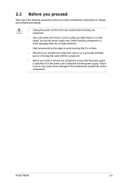
...; Before you install or remove any component, ensure that the power supply is switched off or the power cord is detached from the power supply. ASUS P8B-M 2-3
...; Before you install or remove any component, ensure that the power supply is switched off or the power cord is detached from the power supply. ASUS P8B-M 2-3
User Guide
Page 23
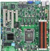
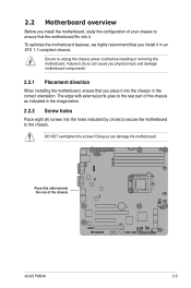
... ports goes to the rear part of the chassis as indicated in an ATX 1.1 compliant chassis. Place this side towards the rear of the chassis ASUS P8B-M 2-5 2.2 Motherboard overview Before you install the motherboard, study the configuration of your chassis to unplug the chassis power cord before installing or removing the motherboard...
... ports goes to the rear part of the chassis as indicated in an ATX 1.1 compliant chassis. Place this side towards the rear of the chassis ASUS P8B-M 2-5 2.2 Motherboard overview Before you install the motherboard, study the configuration of your chassis to unplug the chassis power cord before installing or removing the motherboard...
User Guide
Page 25
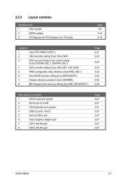
... 3. PS/2 keyboard port (purple) 4. RAID configuration utility selection (3-pin RAID_SEL1) 6. CPU sockets 2. LAN 2 (RJ-45) port Page 2-27 2-27 2-27 2-27 2-27 2-27 2-27 2-27 ASUS P8B-M 2-7 CPU Fan and Chassis Fan control setting (3-pin CPUFAN_SEL1, CHAFAN_SEL1) 4. USB 2.0 ports 1 and 2 5. 2.2.4 Layout contents Slots/Soocket 1. PCI Express x8 / PCI Express x16 / PCI slots...
... 3. PS/2 keyboard port (purple) 4. RAID configuration utility selection (3-pin RAID_SEL1) 6. CPU sockets 2. LAN 2 (RJ-45) port Page 2-27 2-27 2-27 2-27 2-27 2-27 2-27 2-27 ASUS P8B-M 2-7 CPU Fan and Chassis Fan control setting (3-pin CPUFAN_SEL1, CHAFAN_SEL1) 4. USB 2.0 ports 1 and 2 5. 2.2.4 Layout contents Slots/Soocket 1. PCI Express x8 / PCI Express x16 / PCI slots...
User Guide
Page 27
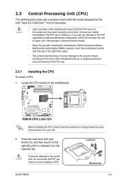
... warranty does not cover damage to the socket pins, do not remove the PnP cap unless you are not bent. Load lever A B Retention tab ASUS P8B-M 2-9 Before installing the CPU, ensure that the PnP cap is missing, or if you see any damage to the right (B) until it is on... your retailer immediately if the PnP cap is on the motherboard. ASUS will shoulder the cost of the PnP cap. 2.3.1 Installing the CPU To install a CPU: 1. ASUS will process Return Merchandise Authorization (RMA) requests only if the motherboard comes with your thumb (A), and then...
... warranty does not cover damage to the socket pins, do not remove the PnP cap unless you are not bent. Load lever A B Retention tab ASUS P8B-M 2-9 Before installing the CPU, ensure that the PnP cap is missing, or if you see any damage to the right (B) until it is on... your retailer immediately if the PnP cap is on the motherboard. ASUS will shoulder the cost of the PnP cap. 2.3.1 Installing the CPU To install a CPU: 1. ASUS will process Return Merchandise Authorization (RMA) requests only if the motherboard comes with your thumb (A), and then...
User Guide
Page 29
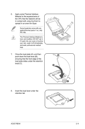
6. If so, skip this step. The Thermal Interface Material is spread in contact with preapplied thermal paste. B A C 8. Insert the load lever under the retention knob (C). ASUS P8B-M 2-11 Some heatsinks come with , ensuring that it is toxic and inedible. DO NOT eat it off immediately, and seek professional medical help. 7. If it ...
6. If so, skip this step. The Thermal Interface Material is spread in contact with preapplied thermal paste. B A C 8. Insert the load lever under the retention knob (C). ASUS P8B-M 2-11 Some heatsinks come with , ensuring that it is toxic and inedible. DO NOT eat it off immediately, and seek professional medical help. 7. If it ...
User Guide
Page 31
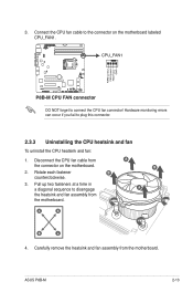
... the connector on the motherboard labeled CPU_FAN1. Hardware monitoring errors can occur if you fail to connect the CPU fan connector! Rotate each fastener B counterclockwise. 3. ASUS P8B-M 2-13 Carefully remove the heatsink and fan assembly from the motherboard. DO NOT forget to plug this connector. 2.3.3 Uninstalling the CPU heatsink and fan To...
... the connector on the motherboard labeled CPU_FAN1. Hardware monitoring errors can occur if you fail to connect the CPU fan connector! Rotate each fastener B counterclockwise. 3. ASUS P8B-M 2-13 Carefully remove the heatsink and fan assembly from the motherboard. DO NOT forget to plug this connector. 2.3.3 Uninstalling the CPU heatsink and fan To...

User Guide
Page 33
... into the DIMM sockets using the memory configurations in this section. For optimum compatibility, it is notched differently to prevent installation on a DDR2 DIMM socket. ASUS P8B-M 2-15 DDR3 modules are developed for better performance with four Double Data Rate 3 (DDR3) Dual Inline Memory Modules (DIMM) sockets. 2.4 System memory 2.4.1 Overview The motherboard...
... into the DIMM sockets using the memory configurations in this section. For optimum compatibility, it is notched differently to prevent installation on a DDR2 DIMM socket. ASUS P8B-M 2-15 DDR3 modules are developed for better performance with four Double Data Rate 3 (DDR3) Dual Inline Memory Modules (DIMM) sockets. 2.4 System memory 2.4.1 Overview The motherboard...
User Guide
Page 35
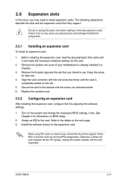
... the necessary BIOS settings, if any. The following subsections describe the slots and the expansion cards that came with it by adjusting the software settings. 1. ASUS P8B-M 2-17
... the necessary BIOS settings, if any. The following subsections describe the slots and the expansion cards that came with it by adjusting the software settings. 1. ASUS P8B-M 2-17

User Guide
Page 37
Locate the BMC_FW header on your motherboard. 1. Orient and press the ASMB5 management card in place. PCI slot PCIe x8 slot (x4 link) PCIe x16 slot (x16 link) PCIe x8 slot (x4 link) 2.5.7 Installing ASMB5 management card Follow the steps below to install an optional ASMB5 management card on the motherboard. 2. ASUS P8B-M 2-19
Locate the BMC_FW header on your motherboard. 1. Orient and press the ASMB5 management card in place. PCI slot PCIe x8 slot (x4 link) PCIe x16 slot (x16 link) PCIe x8 slot (x4 link) 2.5.7 Installing ASMB5 management card Follow the steps below to install an optional ASMB5 management card on the motherboard. 2. ASUS P8B-M 2-19
User Guide
Page 39
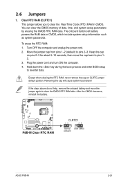
... button cell battery powers the RAM data in CMOS. Keep the cap on CLRTC jumper default position. Removing the cap will cause system boot failure! ASUS P8B-M 2-21 Hold down the key during the boot process and enter BIOS setup to pins 2-3. Move the jumper cap from pins 1-2 (default) to re-enter...
... button cell battery powers the RAM data in CMOS. Keep the cap on CLRTC jumper default position. Removing the cap will cause system boot failure! ASUS P8B-M 2-21 Hold down the key during the boot process and enter BIOS setup to pins 2-3. Move the jumper cap from pins 1-2 (default) to re-enter...
User Guide
Page 41
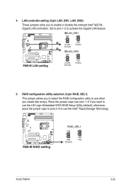
... use the LSI Logic Embedded SATA RAID Setup Utility (default); otherwise, place the jumper caps to pins 2-3 to use the Intel® Rapid Storage Technology. ASUS P8B-M 2-23 Place the jumper caps over pins 1-2 if you create disk arrays. Set to pins 1-2 to enable or disable the onboard Intel® 82574L Gigabit...
... use the LSI Logic Embedded SATA RAID Setup Utility (default); otherwise, place the jumper caps to pins 2-3 to use the Intel® Rapid Storage Technology. ASUS P8B-M 2-23 Place the jumper caps over pins 1-2 if you create disk arrays. Set to pins 1-2 to enable or disable the onboard Intel® 82574L Gigabit...
User Guide
Page 43
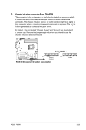
... intend to this connector when a chassis component is removed or replaced. Chassis intrusion connector (2-pin CHASSIS) This connector is then generated as a chassis intrusion event. ASUS P8B-M 2-25 The signal is for a chassis-mounted intrusion detection sensor or switch. 7. Connect one end of the chassis intrusion sensor or switch cable to use...
... intend to this connector when a chassis component is removed or replaced. Chassis intrusion connector (2-pin CHASSIS) This connector is then generated as a chassis intrusion event. ASUS P8B-M 2-25 The signal is for a chassis-mounted intrusion detection sensor or switch. 7. Connect one end of the chassis intrusion sensor or switch cable to use...

User Guide
Page 45
... BLINKING Data activity Speed LED Status Description OFF 10 Mbps connection ORANGE 100 Mbps connection GREEN 1 Gbps connection ACT/LINK SPEED LED LED LAN port ASUS P8B-M 2-27 PS/2 mouse port (green).
... BLINKING Data activity Speed LED Status Description OFF 10 Mbps connection ORANGE 100 Mbps connection GREEN 1 Gbps connection ACT/LINK SPEED LED LED LAN port ASUS P8B-M 2-27 PS/2 mouse port (green).

User Guide
Page 47
... the back of any device connected to 480 Mbps connection speed. Hard disk activity LED connector (4-pin HDLED1) This LED connector is for USB 2.0 ports. ASUS P8B-M 2-29 USB connector (10-1 pin USB34, USB56;
... the back of any device connected to 480 Mbps connection speed. Hard disk activity LED connector (4-pin HDLED1) This LED connector is for USB 2.0 ports. ASUS P8B-M 2-29 USB connector (10-1 pin USB34, USB56;
User Guide
Page 49
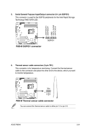
Connect the thermal sensor cable to this connector and place the other end to the device, which you want to either pin 1-2 or pin 2-3. You can connect the thermal sensor cable to monitor temperature. ASUS P8B-M 2-31 Serial General Purpose Input/Output connector (6-1 pin SGPIO1) This connector is for the Intel Rapid Storage Technology RAID SATA LED. 6. 5. Thermal sensor cable connectors (3-pin TR1) This connector is used for the SGPIO peripherals for temperature monitoring.
Connect the thermal sensor cable to this connector and place the other end to the device, which you want to either pin 1-2 or pin 2-3. You can connect the thermal sensor cable to monitor temperature. ASUS P8B-M 2-31 Serial General Purpose Input/Output connector (6-1 pin SGPIO1) This connector is for the Intel Rapid Storage Technology RAID SATA LED. 6. 5. Thermal sensor cable connectors (3-pin TR1) This connector is used for the SGPIO peripherals for temperature monitoring.
User Guide
Page 51
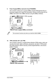
... keys, digital certificates, passwords, and data. Power Supply SMBus connector (5-pin PSUSMB1) This connector allows you install the ASUS ASMB5. 10. A TPM system also helps enhance network security, protects digital identities, and ensures platform integrity. ASUS P8B-M 2-33 Devices communicate with an SMBus host and/or other SMBus devices using the SMBus interface. 9.
... keys, digital certificates, passwords, and data. Power Supply SMBus connector (5-pin PSUSMB1) This connector allows you install the ASUS ASMB5. 10. A TPM system also helps enhance network security, protects digital identities, and ensures platform integrity. ASUS P8B-M 2-33 Devices communicate with an SMBus host and/or other SMBus devices using the SMBus interface. 9.
User Guide
Page 53
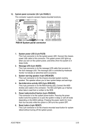
... connector (20-1 pin PANEL1) This connector supports several chassis-mounted functions. 1. System warning speaker (4-pin SPEAKER) This 4-pin connector is ON turns the system OFF. 6. ASUS P8B-M 2-35 Connect the chassis power LED cable to the HDD. 5. Reset button (2-pin RESET) This 2-pin connector is for the chassis-mounted reset button for...
... connector (20-1 pin PANEL1) This connector supports several chassis-mounted functions. 1. System warning speaker (4-pin SPEAKER) This 4-pin connector is ON turns the system OFF. 6. ASUS P8B-M 2-35 Connect the chassis power LED cable to the HDD. 5. Reset button (2-pin RESET) This 2-pin connector is for the chassis-mounted reset button for...


