User Manual
Page 11
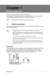
...due to static electricity • Hold components by the edges to the motherboard, peripherals, or components. Refer to page ix for buying an ASUS® P7H55-M SI motherboard! The illustration below shows the location of the following precautions before you install motherboard components or change any motherboard settings. • Unplug ... grounded object or a metal object, such as the power supply case, to avoid damaging them . • Whenever you uninstall any motherboard component. SB_PWR P7H55-M SI ON OFF Standby Power Powered Off P7H55-M SI Onboard LED ASUS P7H55-M SI 1-1
...due to static electricity • Hold components by the edges to the motherboard, peripherals, or components. Refer to page ix for buying an ASUS® P7H55-M SI motherboard! The illustration below shows the location of the following precautions before you install motherboard components or change any motherboard settings. • Unplug ... grounded object or a metal object, such as the power supply case, to avoid damaging them . • Whenever you uninstall any motherboard component. SB_PWR P7H55-M SI ON OFF Standby Power Powered Off P7H55-M SI Onboard LED ASUS P7H55-M SI 1-1
User Manual
Page 13
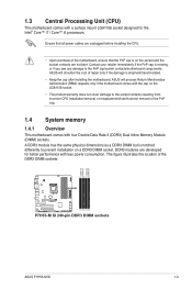
... better performance with a surface mount LGA1156 socket designed for the Intel® Core™ i7 / Core™ i5 processors. DDR3 modules are not bent. ASUS will process Return Merchandise Authorization (RMA) requests only if the motherboard comes with four Double Data Rate 3 (DDR3) Dual Inline Memory Module (DIMM) sockets.... see any damage to the socket contacts resulting from incorrect CPU installation/removal, or misplacement/loss/incorrect removal of the DDR3 DIMM sockets: P7H55-M SI P7H55-M SI 240-pin DDR3 DIMM sockets DIMM_A2 DIMM_A1 DIMM_B2 DIMM_B1 ASUS P7H55-M SI 1-3
... better performance with a surface mount LGA1156 socket designed for the Intel® Core™ i7 / Core™ i5 processors. DDR3 modules are not bent. ASUS will process Return Merchandise Authorization (RMA) requests only if the motherboard comes with four Double Data Rate 3 (DDR3) Dual Inline Memory Module (DIMM) sockets.... see any damage to the socket contacts resulting from incorrect CPU installation/removal, or misplacement/loss/incorrect removal of the DDR3 DIMM sockets: P7H55-M SI P7H55-M SI 240-pin DDR3 DIMM sockets DIMM_A2 DIMM_A1 DIMM_B2 DIMM_B1 ASUS P7H55-M SI 1-3
User Manual
Page 15
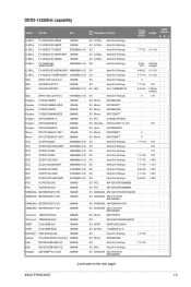
...-Sink Package - - • •• Kingtiger 2GB DIMM PC3-10666 2048MB DS SAMSUNG SEC 904 HCH9 K4B1G0846D - - • •• (continued on the next page) ASUS P7H55-M SI 1-5 Heat-Sink Package 9 1.5V • • • Kingmax FLFD45F-B8MF9 1024MB SS Micron 8HD22D9JNM - - • •• Kingmax FLFD45F-B8MH9 MAES 1024MB SS Micron 9CF22D9KPT...
...-Sink Package - - • •• Kingtiger 2GB DIMM PC3-10666 2048MB DS SAMSUNG SEC 904 HCH9 K4B1G0846D - - • •• (continued on the next page) ASUS P7H55-M SI 1-5 Heat-Sink Package 9 1.5V • • • Kingmax FLFD45F-B8MF9 1024MB SS Micron 8HD22D9JNM - - • •• Kingmax FLFD45F-B8MH9 MAES 1024MB SS Micron 9CF22D9KPT...

User Manual
Page 17
... Express x16 slot This motherboard supports PCI Express x16 graphics cards that they support. Secure the card to the chassis with the PCI Express specifications. ASUS P7H55-M SI 1-7 Remove the bracket opposite the slot that the cards do so may need IRQ assignments; Failure to do not need to install expansion cards. Replace...
... Express x16 slot This motherboard supports PCI Express x16 graphics cards that they support. Secure the card to the chassis with the PCI Express specifications. ASUS P7H55-M SI 1-7 Remove the bracket opposite the slot that the cards do so may need IRQ assignments; Failure to do not need to install expansion cards. Replace...
User Manual
Page 19
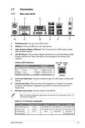
... Speaker Out Mic In - 6-channel Rear Speaker Out Front Speaker Out Bass/Center - 8-channel Rear Speaker Out Front Speaker Out Bass/Center Side Speaker Out ASUS P7H55-M SI 1-9 Line Out port (lime). Refer to the audio configuration table below for the function of this port becomes Front Speaker Out. 7. Refer to the table...
... Speaker Out Mic In - 6-channel Rear Speaker Out Front Speaker Out Bass/Center - 8-channel Rear Speaker Out Front Speaker Out Bass/Center Side Speaker Out ASUS P7H55-M SI 1-9 Line Out port (lime). Refer to the audio configuration table below for the function of this port becomes Front Speaker Out. 7. Refer to the table...

User Manual
Page 21
...RSATA_TXN6 GND RSATA_RXP6 RSATA_RXN6 GND SATA6 Install the Windows® XP Service Pack 2 or later version before using Serial ATA. 3. ASUS P7H55-M SI 1-11 The data transfer rate of the Serial ATA 3Gb/s is faster than the standard parallel ATA with Serial ATA 1.5Gb/s ... These connectors are for the Serial ATA signal cables for an additional Sony/Philips Digital Interface (S/PDIF) port. +5V SPDIFOUT GND P7H55-M SI SPDIF_OUT P7H55-M SI Digital audio connector The S/PDIF module is backward compatible with 133MB/s (Ultra DMA133). The Serial ATA 3Gb/s is purchased separately....
...RSATA_TXN6 GND RSATA_RXP6 RSATA_RXN6 GND SATA6 Install the Windows® XP Service Pack 2 or later version before using Serial ATA. 3. ASUS P7H55-M SI 1-11 The data transfer rate of the Serial ATA 3Gb/s is faster than the standard parallel ATA with Serial ATA 1.5Gb/s ... These connectors are for the Serial ATA signal cables for an additional Sony/Philips Digital Interface (S/PDIF) port. +5V SPDIFOUT GND P7H55-M SI SPDIF_OUT P7H55-M SI Digital audio connector The S/PDIF module is backward compatible with 133MB/s (Ultra DMA133). The Serial ATA 3Gb/s is purchased separately....
User Manual
Page 23
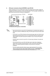
..., refer to install additional devices. 6. The plugs from the power supply are for an ATX power supply. ATX12V EATXPWR +12V DC +12V DC P7H55-M SI GND GND +3 Volts +12 Volts +12 Volts +5V Standby Power OK PIN 1 GND +5 Volts GND +5 Volts GND +3 Volts +3 Volts PIN... otherwise, the system will not boot up if the power is inadequate. • If you intend to fit these connectors in only one orientation. ASUS P7H55-M SI 1-13 Find the proper orientation and push down firmly until the connectors completely fit. The system may become unstable or may not boot up . •...
..., refer to install additional devices. 6. The plugs from the power supply are for an ATX power supply. ATX12V EATXPWR +12V DC +12V DC P7H55-M SI GND GND +3 Volts +12 Volts +12 Volts +5V Standby Power OK PIN 1 GND +5 Volts GND +5 Volts GND +3 Volts +3 Volts PIN... otherwise, the system will not boot up if the power is inadequate. • If you intend to fit these connectors in only one orientation. ASUS P7H55-M SI 1-13 Find the proper orientation and push down firmly until the connectors completely fit. The system may become unstable or may not boot up . •...
User Manual
Page 25
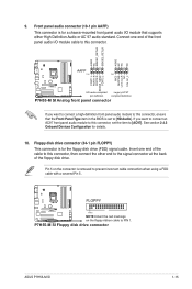
... connector is for details. 10. Pin 5 on the floppy ribbon cable to prevent incorrect cable connection when using a FDD cable with a covered Pin 5. 9. P7H55-M SI Floppy disk drive connector ASUS P7H55-M SI 1-15 AGND NC SENSE1_RETUR SENSE2_RETUR AGND NC NC NC AAFP PIN 1 PIN 1 MIC2 MICPWR Line out_R NC Line out_L PORT1 L PORT1 R PORT2 R SENSE_SEND...
... connector is for details. 10. Pin 5 on the floppy ribbon cable to prevent incorrect cable connection when using a FDD cable with a covered Pin 5. 9. P7H55-M SI Floppy disk drive connector ASUS P7H55-M SI 1-15 AGND NC SENSE1_RETUR SENSE2_RETUR AGND NC NC NC AAFP PIN 1 PIN 1 MIC2 MICPWR Line out_R NC Line out_L PORT1 L PORT1 R PORT2 R SENSE_SEND...
User Manual
Page 27
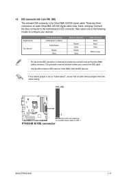
... set as "Cable-Select", ensure that all other device jumpers have the same setting. PRI_IDE PIN1 P7H55-M SI NOTE:Orient the red markings on each Ultra DMA 133/100 signal cable: blue, black, and gray. P7H55-M SI IDE connector ASUS P7H55-M SI 1-17 This prevents incorrect insertion when you connect the IDE cable. • Use the 80...
... set as "Cable-Select", ensure that all other device jumpers have the same setting. PRI_IDE PIN1 P7H55-M SI NOTE:Orient the red markings on each Ultra DMA 133/100 signal cable: blue, black, and gray. P7H55-M SI IDE connector ASUS P7H55-M SI 1-17 This prevents incorrect insertion when you connect the IDE cable. • Use the 80...

User Manual
Page 29
... To update the BIOS: 1. Chapter 2 BIOS information 2.1 Managing and updating your BIOS Save a copy of the updating process: ASUS P7H55-M SI 2-1 Installing ASUS Update To install ASUS Update: 1. From the Windows® desktop, click Start > Programs > ASUS > ASUSUpdate > ASUSUpdate to manage, save, and update the motherboard BIOS in case you need to complete the installation. The...
... To update the BIOS: 1. Chapter 2 BIOS information 2.1 Managing and updating your BIOS Save a copy of the updating process: ASUS P7H55-M SI 2-1 Installing ASUS Update To install ASUS Update: 1. From the Windows® desktop, click Start > Programs > ASUS > ASUSUpdate > ASUSUpdate to manage, save, and update the motherboard BIOS in case you need to complete the installation. The...

User Manual
Page 31
... support DVD and a USB flash drive in DOS environment 1. Booting the system in FAT32/16 format and single partition. 2. When the ASUS Logo appears, press to boot using defaults ASUS P7H55-M SI 2-3 Before updating BIOS 1. Insert the support DVD into the optical drive and select the optical drive as a backup when the BIOS fails...
... support DVD and a USB flash drive in DOS environment 1. Booting the system in FAT32/16 format and single partition. 2. When the ASUS Logo appears, press to boot using defaults ASUS P7H55-M SI 2-3 Before updating BIOS 1. Insert the support DVD into the optical drive and select the optical drive as a backup when the BIOS fails...

User Manual
Page 33
.... Press to switch between screen fields and use the keys to exit BIOS Updater. Select the Load Setup Defaults item under the Exit BIOS menu. ASUS P7H55-M SI 2-5 Yes No 4. Select Yes and press . See section 2.8 Exit menu for DOS V1.00b [09/06/22] FLASH TYPE: Winbond 25X/Q64 Current ROM... BOARD: P7H55-M SI VER: 0207 DATE: 12/14/2009 Update ROM BOARD: Unknown VER: Unknown DATE: Unknown PATH: A:\ A: P7H55M.ROM 2097152 2009-12-14 17:30:48 ...
.... Press to switch between screen fields and use the keys to exit BIOS Updater. Select the Load Setup Defaults item under the Exit BIOS menu. ASUS P7H55-M SI 2-5 Yes No 4. Select Yes and press . See section 2.8 Exit menu for DOS V1.00b [09/06/22] FLASH TYPE: Winbond 25X/Q64 Current ROM... BOARD: P7H55-M SI VER: 0207 DATE: 12/14/2009 Update ROM BOARD: Unknown VER: Unknown DATE: Unknown PATH: A:\ A: P7H55M.ROM 2097152 2009-12-14 17:30:48 ...

User Manual
Page 35
... always shut down the system properly from a running operating system can cause damage to your screen. • Visit the ASUS website at startup: • Press during the Power-On Self Test (POST). ASUS P7H55-M SI 2-7 2.2 BIOS setup program Use the BIOS Setup program to update the BIOS or configure its routines. Entering BIOS Setup...
... always shut down the system properly from a running operating system can cause damage to your screen. • Visit the ASUS website at startup: • Press during the Power-On Self Test (POST). ASUS P7H55-M SI 2-7 2.2 BIOS setup program Use the BIOS Setup program to update the BIOS or configure its routines. Entering BIOS Setup...
User Manual
Page 37
... Time Out (Sec) [35] Selects the time out value for the SATA devices installed in the system. Configuration options: [0] [5] [10] [15] [20] [25] [30] [35] ASUS P7H55-M SI 2-9 Configuration options: [Disabled] [Enabled] 2.3.6 Storage Configuration The items in this mode, and if the device was not previously formatted with OS built-in Windows XP...
... Time Out (Sec) [35] Selects the time out value for the SATA devices installed in the system. Configuration options: [0] [5] [10] [15] [20] [25] [30] [35] ASUS P7H55-M SI 2-9 Configuration options: [Disabled] [Enabled] 2.3.6 Storage Configuration The items in this mode, and if the device was not previously formatted with OS built-in Windows XP...

User Manual
Page 39
... item to [Enabled] allows Legacy OSes to activate in the near future. With virtualization, one computer system can function as well. Configuration options: [Enabled] [Disabled] ASUS P7H55-M SI 2-11 Intel(R) SpeedStep(TM) Tech [Enabled] When this item to [Enabled] allows legacy operating systems to run multiple operating systems and applications in independent partitions...
... item to [Enabled] allows Legacy OSes to activate in the near future. With virtualization, one computer system can function as well. Configuration options: [Enabled] [Disabled] ASUS P7H55-M SI 2-11 Intel(R) SpeedStep(TM) Tech [Enabled] When this item to [Enabled] allows legacy operating systems to run multiple operating systems and applications in independent partitions...
User Manual
Page 41
... options: [Disabled] [2F8/IRQ3] [3E8/IRQ4] [2E8/IRQ3] Parallel Port Address [378] Allows you to select the Parallel Port base addresses. Configuration options: [IRQ5] [IRQ7] ASUS P7H55-M SI 2-13 If High Definition Audio Front Panel used, please set the Parallel Port ECP DMA. Configuration options: [Disabled] [Enabled] Onboard LAN [Enabled] Allows you to...
... options: [Disabled] [2F8/IRQ3] [3E8/IRQ4] [2E8/IRQ3] Parallel Port Address [378] Allows you to select the Parallel Port base addresses. Configuration options: [IRQ5] [IRQ7] ASUS P7H55-M SI 2-13 If High Definition Audio Front Panel used, please set the Parallel Port ECP DMA. Configuration options: [Disabled] [Enabled] Onboard LAN [Enabled] Allows you to...
User Manual
Page 43
...], and then press to display the configuration options. TCG/TPM Support [Yes] Allows you to enable or disable TCG/TPM setting. Configuration options: [Disabled] [Enabled] ASUS P7H55-M SI 2-15 After you select [OK] to execute the Clearing the TPM function, the data saved in the TPM security chip will appear to ask if...
...], and then press to display the configuration options. TCG/TPM Support [Yes] Allows you to enable or disable TCG/TPM setting. Configuration options: [Disabled] [Enabled] ASUS P7H55-M SI 2-15 After you select [OK] to execute the Clearing the TPM function, the data saved in the TPM security chip will appear to ask if...

User Manual
Page 45
... monitor automatically detects and displays the motherboard and CPU temperatures. This feature requires an ATX power supply that provides at least 1A on the system. ASUS P7H55-M SI 2-17
... monitor automatically detects and displays the motherboard and CPU temperatures. This feature requires an ATX power supply that provides at least 1A on the system. ASUS P7H55-M SI 2-17
User Manual
Page 47
... RAM. To set to [Enabled], the system displays the message Press DEL to the Setup items. Configuration options: [No Access] [View Only] [Limited] [Full Access] ASUS P7H55-M SI 2-19 The message Password uninstalled appears. Configuration options: [Disabled] [Enabled] 2.6.3 Security The Security menu items allow you to allow you have set your BIOS password...
... RAM. To set to [Enabled], the system displays the message Press DEL to the Setup items. Configuration options: [No Access] [View Only] [Limited] [Full Access] ASUS P7H55-M SI 2-19 The message Password uninstalled appears. Configuration options: [Disabled] [Enabled] 2.6.3 Security The Security menu items allow you to allow you have set your BIOS password...
User Manual
Page 49
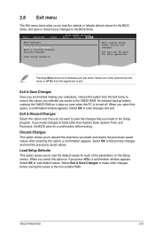
... appears. Pressing does not immediately exit this option, a confirmation appears. After selecting this menu. Load Setup Defaults This option allows you to load default values. ASUS P7H55-M SI 2-21 2.8 Exit menu The Exit menu items allow you to load the optimal or failsafe default values for the BIOS items, and save or discard...
... appears. Pressing does not immediately exit this option, a confirmation appears. After selecting this menu. Load Setup Defaults This option allows you to load default values. ASUS P7H55-M SI 2-21 2.8 Exit menu The Exit menu items allow you to load the optimal or failsafe default values for the BIOS items, and save or discard...


