User Manual
Page 12
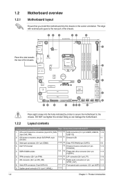
...P7H55-M SI PCI1 Intel® GMA4500 SATA1 SATA2 7 8Mb BIOS 8 SATA3 SATA4 SATA5 SATA6 VIA VT1708S AAFP SPDIF_OUT LPT PCI2 17 16 15 FLOPPY USB1112 USB910 USB78 CHASSIS CLRTC 9 SB_PWR F_PANEL 14 13 12 11 10 Place eight screws into the chassis in the correct orientation. Doing so can damage the motherboard.... 1.2.2 Layout contents Connectors/Jumpers/Slots/LED Page Connectors/Jumpers/Slots/LED Page 1. Intel® CPU socket 13. Serial ATA connectors (7-pin SATA1-6) 1-11 17. ...
...P7H55-M SI PCI1 Intel® GMA4500 SATA1 SATA2 7 8Mb BIOS 8 SATA3 SATA4 SATA5 SATA6 VIA VT1708S AAFP SPDIF_OUT LPT PCI2 17 16 15 FLOPPY USB1112 USB910 USB78 CHASSIS CLRTC 9 SB_PWR F_PANEL 14 13 12 11 10 Place eight screws into the chassis in the correct orientation. Doing so can damage the motherboard.... 1.2.2 Layout contents Connectors/Jumpers/Slots/LED Page Connectors/Jumpers/Slots/LED Page 1. Intel® CPU socket 13. Serial ATA connectors (7-pin SATA1-6) 1-11 17. ...
User Manual
Page 13
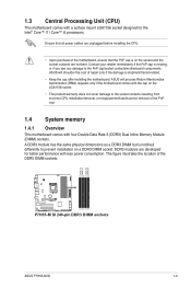
... for better performance with a surface mount LGA1156 socket designed for the Intel® Core™ i7 / Core™ i5 processors. ASUS will process Return Merchandise Authorization (RMA) requests only if the motherboard comes with four Double Data Rate 3 (DDR3) Dual Inline Memory ... P7H55-M SI P7H55-M SI 240-pin DDR3 DIMM sockets DIMM_A2 DIMM_A1 DIMM_B2 DIMM_B1 ASUS P7H55-M SI 1-3 Ensure that the PnP cap is notched differently to prevent installation on the LGA1156 socket. • The product warranty does not cover damage to the PnP cap/socket contacts/motherboard components...
... for better performance with a surface mount LGA1156 socket designed for the Intel® Core™ i7 / Core™ i5 processors. ASUS will process Return Merchandise Authorization (RMA) requests only if the motherboard comes with four Double Data Rate 3 (DDR3) Dual Inline Memory ... P7H55-M SI P7H55-M SI 240-pin DDR3 DIMM sockets DIMM_A2 DIMM_A1 DIMM_B2 DIMM_B1 ASUS P7H55-M SI 1-3 Ensure that the PnP cap is notched differently to prevent installation on the LGA1156 socket. • The product warranty does not cover damage to the PnP cap/socket contacts/motherboard components...
User Manual
Page 43
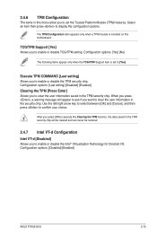
... item then press to enable or disable TCG/TPM setting. Configuration options: [Disabled] [Enabled] ASUS P7H55-M SI 2-15 Execute TPM COMMAND [Last setting] Allows you to display the configuration options. Configuration options...When you press , a warning message will be cleared and can never be restored. 2.4.7 Intel VT-d Configuration Intel VT-d [Disabled] Allows you to enable or disable the TPM security chip. Use the left...you want to confirm your choice. 2.4.6 TPM Configuration The items in this motherboard. After you select [OK] to execute the Clearing the TPM function, the...
... item then press to enable or disable TCG/TPM setting. Configuration options: [Disabled] [Enabled] ASUS P7H55-M SI 2-15 Execute TPM COMMAND [Last setting] Allows you to display the configuration options. Configuration options...When you press , a warning message will be cleared and can never be restored. 2.4.7 Intel VT-d Configuration Intel VT-d [Disabled] Allows you to enable or disable the TPM security chip. Use the left...you want to confirm your choice. 2.4.6 TPM Configuration The items in this motherboard. After you select [OK] to execute the Clearing the TPM function, the...


