User Manual
Page 4
... (system panel 2-37 2.9 Starting up for the first time 2-38 2.10 Turning off the computer 2-38 Chapter 3: BIOS setup 3.1 Knowing BIOS 3-1 3.2 Updating BIOS 3-1 3.2.1 ASUS Update utility 3-2 3.2.2 ASUS EZ Flash 2 utility 3-4 3.2.3 ASUS CrashFree BIOS 3 utility 3-5 3.3 BIOS setup program 3-6 3.3.1 BIOS menu screen 3-6 3.3.2 Menu bar 3-6 3.3.3 Navigation keys 3-7 3.3.4 Menu items 3-7 3.3.5 Submenu items 3-7 3.3.6 Configuration fields 3-7 3.3.7 Pop-up window 3-7 3.3.8 Scroll bar 3-7 3.3.9 General help 3-7 3.4 Main menu...
... (system panel 2-37 2.9 Starting up for the first time 2-38 2.10 Turning off the computer 2-38 Chapter 3: BIOS setup 3.1 Knowing BIOS 3-1 3.2 Updating BIOS 3-1 3.2.1 ASUS Update utility 3-2 3.2.2 ASUS EZ Flash 2 utility 3-4 3.2.3 ASUS CrashFree BIOS 3 utility 3-5 3.3 BIOS setup program 3-6 3.3.1 BIOS menu screen 3-6 3.3.2 Menu bar 3-6 3.3.3 Navigation keys 3-7 3.3.4 Menu items 3-7 3.3.5 Submenu items 3-7 3.3.6 Configuration fields 3-7 3.3.7 Pop-up window 3-7 3.3.8 Scroll bar 3-7 3.3.9 General help 3-7 3.4 Main menu...
User Manual
Page 6
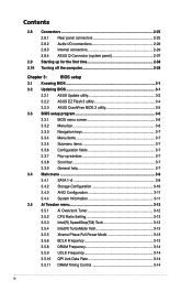
... Probe II 4-3 4.3.2 ASUS AI Suite 4-4 4.3.3 ASUS EPU 4-5 4.3.4 ASUS Fan Xpert 4-6 4.3.5 ASUS TurboV 4-7 4.3.6 ASUS Express Gate SSD 4-8 4.3.7 Audio configurations 4-9 4.4 RAID configurations 4-10 4.4.1 RAID definitions 4-10 4.4.2 Installing Serial ATA hard disks 4-11 4.4.3 Setting the RAID item in BIOS 4-11 4.4.4 Intel® Matrix Storage Manager option ROM utility 4-11 4.5 Creating a RAID driver disk 4-15 4.5.1 Creating a RAID driver disk without...
... Probe II 4-3 4.3.2 ASUS AI Suite 4-4 4.3.3 ASUS EPU 4-5 4.3.4 ASUS Fan Xpert 4-6 4.3.5 ASUS TurboV 4-7 4.3.6 ASUS Express Gate SSD 4-8 4.3.7 Audio configurations 4-9 4.4 RAID configurations 4-10 4.4.1 RAID definitions 4-10 4.4.2 Installing Serial ATA hard disks 4-11 4.4.3 Setting the RAID item in BIOS 4-11 4.4.4 Intel® Matrix Storage Manager option ROM utility 4-11 4.5 Creating a RAID driver disk 4-15 4.5.1 Creating a RAID driver disk without...
User Manual
Page 9
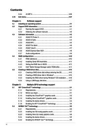
... updates. 1. Where to find more information Refer to change system settings through the BIOS Setup menus. ASUS websites The ASUS website provides updated information on the motherboard. • Chapter 3: BIOS setup This chapter tells how to the following parts: • Chapter 1: Product ... package and the software. • Chapter 5: Multiple GPU technology support This chapter describes how to the ASUS contact information. 2. Detailed descriptions of the BIOS parameters are not part of the motherboard and the new technology it supports. • Chapter 2: Hardware information...
... updates. 1. Where to find more information Refer to change system settings through the BIOS Setup menus. ASUS websites The ASUS website provides updated information on the motherboard. • Chapter 3: BIOS setup This chapter tells how to the following parts: • Chapter 1: Product ... package and the software. • Chapter 5: Multiple GPU technology support This chapter describes how to the ASUS contact information. 2. Detailed descriptions of the BIOS parameters are not part of the motherboard and the new technology it supports. • Chapter 2: Hardware information...
User Manual
Page 12
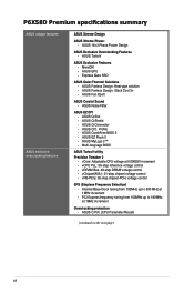
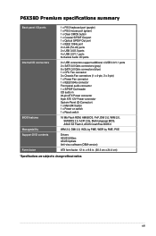
... voltage control - vDRAM Bus: 49-step DRAM voltage control - ASUS C.P.R. (CPU Parameter Recall) (continued on the next page) xii ASUS MyLogo 2™ - Multi-language BIOS ASUS TurboV utility Precision Tweaker 2 - ASUS Noise Filter ASUS EZ DIY - P6X58D Premium specifications summary ASUS unique features ASUS exclusive overclocking features ASUS Xtreme Design ASUS Xtreme Phase: - ASUS CrashFree BIOS 3 - ASUS Q-Shield - MemOK! - vCPU PLL: 36-step reference voltage...
... voltage control - vDRAM Bus: 49-step DRAM voltage control - ASUS C.P.R. (CPU Parameter Recall) (continued on the next page) xii ASUS MyLogo 2™ - Multi-language BIOS ASUS TurboV utility Precision Tweaker 2 - ASUS Noise Filter ASUS EZ DIY - P6X58D Premium specifications summary ASUS unique features ASUS exclusive overclocking features ASUS Xtreme Design ASUS Xtreme Phase: - ASUS CrashFree BIOS 3 - ASUS Q-Shield - MemOK! - vCPU PLL: 36-step reference voltage...
User Manual
Page 13
... Flash ROM, AMI BIOS, PnP, DMI 2.0, WfM 2.0, SM BIOS 2.3, ACPI 2.0a, Multi-language BIOS, ASUS EZ Flash 2, ASUS CrashFree BIOS 3 WfM 2.0, DMI 2.0, WOL by PME, WOR by PME, PXE Drivers ASUS Utilities ASUS Update Anti-virus software (OEM version) ATX form factor: 12 in . (30.5 cm x 24.4 cm) *Specifications are subject to change without notice. P6X58D Premium specifications summary Back...
... Flash ROM, AMI BIOS, PnP, DMI 2.0, WfM 2.0, SM BIOS 2.3, ACPI 2.0a, Multi-language BIOS, ASUS EZ Flash 2, ASUS CrashFree BIOS 3 WfM 2.0, DMI 2.0, WOL by PME, WOR by PME, PXE Drivers ASUS Utilities ASUS Update Anti-virus software (OEM version) ATX form factor: 12 in . (30.5 cm x 24.4 cm) *Specifications are subject to change without notice. P6X58D Premium specifications summary Back...
User Manual
Page 18
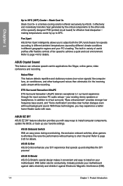
... to install on your PC's loading. Refer to install computer components, update the BIOS, or back up and simplifies the DIY process! Chapter 1 Up to short the pins! ASUS Q-Slot ASUS Q-Slot enhances your DIY experience that speeds up your existing stereo speakers or headphones.... critical components to the other background noises then eliminates it against Electronic Magnetic Interference (EMI). 1-4 Chapter 1: Product Introduction ASUS Onboard Switch With an easy press during overclocking, the exclusive onboard switches allow gamers to effortless fine-tune the performance without...
... to install on your PC's loading. Refer to install computer components, update the BIOS, or back up and simplifies the DIY process! Chapter 1 Up to short the pins! ASUS Q-Slot ASUS Q-Slot enhances your DIY experience that speeds up your existing stereo speakers or headphones.... critical components to the other background noises then eliminates it against Electronic Magnetic Interference (EMI). 1-4 Chapter 1: Product Introduction ASUS Onboard Switch With an easy press during overclocking, the exclusive onboard switches allow gamers to effortless fine-tune the performance without...
User Manual
Page 19
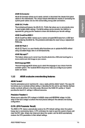
... allows you configure your favorite settings. Simply shut down and reboot the system, and the BIOS automatically restores the CPU parameters to conveniently store or load multiple BIOS settings. ASUS P6X58D Premium 1-5 The localized BIOS setup menu helps you to overclocking failure. ASUS O.C. feature automatically restores the CPU default settings when the system hangs due to update...
... allows you configure your favorite settings. Simply shut down and reboot the system, and the BIOS automatically restores the CPU parameters to conveniently store or load multiple BIOS settings. ASUS P6X58D Premium 1-5 The localized BIOS setup menu helps you to overclocking failure. ASUS O.C. feature automatically restores the CPU default settings when the system hangs due to update...

User Manual
Page 32
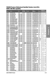
Chapter 2 P6X58D Premium Motherboard Qualified Vendors Lists (QVL) DDR3-2000 MHz capability Vendor Part No. Timing Lable(Bios) DIMM socket Voltage support (Optional) A* B* Crucial BL12864BE2009.8SFB3(EPP) 1GB SS N/A Heat-Sink Package 9-9-9-28(1333-9-9-9-24) ...(3 x 2GB) DS N/A Heat-Sink Package 8-8-8-24(1067-9-9-9-24) 1.65 V V P6X58D Premium Motherboard Qualified Vendors Lists (QVL) DDR3-1866 MHz capability Vendor Part No. Size SS/ DS Chip Brand Chip NO. Timing Lable(Bios) Voltage DIMM socket support (Optional) A* B* CORSAIR BoxP/N:TW3X4G1800C8DF (CM3X2G1800C8D)Ver4.1(XMP)...
Chapter 2 P6X58D Premium Motherboard Qualified Vendors Lists (QVL) DDR3-2000 MHz capability Vendor Part No. Timing Lable(Bios) DIMM socket Voltage support (Optional) A* B* Crucial BL12864BE2009.8SFB3(EPP) 1GB SS N/A Heat-Sink Package 9-9-9-28(1333-9-9-9-24) ...(3 x 2GB) DS N/A Heat-Sink Package 8-8-8-24(1067-9-9-9-24) 1.65 V V P6X58D Premium Motherboard Qualified Vendors Lists (QVL) DDR3-1866 MHz capability Vendor Part No. Size SS/ DS Chip Brand Chip NO. Timing Lable(Bios) Voltage DIMM socket support (Optional) A* B* CORSAIR BoxP/N:TW3X4G1800C8DF (CM3X2G1800C8D)Ver4.1(XMP)...
User Manual
Page 33
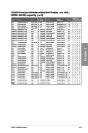
Size SS/ Chip DS Brand Chip NO. Timing Lable(Bios) DIMM socket Voltage support (Optional) A* B* C* D* A-DATA AD31600G001GMU 1GB SS N/A Heat-Sink Package 9-9-9-24 (1333-8-8-8-24) 1.65~1.85 V V V V A-DATA AX3U1600GB1G9-AG 2GB(2 x 1GB) SS N/A Heat-Sink ... 6GB(3 x 2GB) DS N/A Heat-Sink Package 9-9-9-24(1600-7-7-7-20) 1.65 VVV V Patriot PVT36G1600LLK(XMP) 6GB(3 x 2GB) DS N/A Heat-Sink Package 8-8-8-24(1067-7-7-7-20) 1.65 VV ASUS P6X58D Premium 2-13 Chapter 2 P6X58D Premium Motherboard Qualified Vendors Lists (QVL) DDR3-1600 MHz capability Vendor Part No.
Size SS/ Chip DS Brand Chip NO. Timing Lable(Bios) DIMM socket Voltage support (Optional) A* B* C* D* A-DATA AD31600G001GMU 1GB SS N/A Heat-Sink Package 9-9-9-24 (1333-8-8-8-24) 1.65~1.85 V V V V A-DATA AX3U1600GB1G9-AG 2GB(2 x 1GB) SS N/A Heat-Sink ... 6GB(3 x 2GB) DS N/A Heat-Sink Package 9-9-9-24(1600-7-7-7-20) 1.65 VVV V Patriot PVT36G1600LLK(XMP) 6GB(3 x 2GB) DS N/A Heat-Sink Package 8-8-8-24(1067-7-7-7-20) 1.65 VV ASUS P6X58D Premium 2-13 Chapter 2 P6X58D Premium Motherboard Qualified Vendors Lists (QVL) DDR3-1600 MHz capability Vendor Part No.
User Manual
Page 35
... Heat-Sink Package N/A Heat-Sink Package N/A Heat-Sink Package N/A Heat-Sink Package N/A Heat-Sink Package 1GB SS S-POWER I0YT3E0 2GB DS S-POWER I0YT3E0 Timing Lable(Bios) (1066-6-5-5) 9-9-9(1066-7-7-7-20) 7-7-7(1066-7-7-7-20) 8-8-8(1066-7-7-7-16) 9(1333-9-9-9-24) (1066-8-7-7-20) 9(1333-9-9-9-24) 9(1333-9-9-9-24) (1066-8-7-7-20) 9(1333-9-9-9-24) 9(1333-9-9-9-24) Voltage 1.85 1.65 1....VVVV VVVV VVVV VVVV VVVV VVVV VVVV VVVV VVVV VVVV VVVV VV V VVVV VVVV VVVV VV V VVVV VV VVVV 9(1333-9-9-9-24) N/A VVVV 9(1333-9-9-9-24) N/A VVVV ASUS P6X58D Premium 2-15
... Heat-Sink Package N/A Heat-Sink Package N/A Heat-Sink Package N/A Heat-Sink Package N/A Heat-Sink Package 1GB SS S-POWER I0YT3E0 2GB DS S-POWER I0YT3E0 Timing Lable(Bios) (1066-6-5-5) 9-9-9(1066-7-7-7-20) 7-7-7(1066-7-7-7-20) 8-8-8(1066-7-7-7-16) 9(1333-9-9-9-24) (1066-8-7-7-20) 9(1333-9-9-9-24) 9(1333-9-9-9-24) (1066-8-7-7-20) 9(1333-9-9-9-24) 9(1333-9-9-9-24) Voltage 1.85 1.65 1....VVVV VVVV VVVV VVVV VVVV VVVV VVVV VVVV VVVV VVVV VVVV VV V VVVV VVVV VVVV VV V VVVV VV VVVV 9(1333-9-9-9-24) N/A VVVV 9(1333-9-9-9-24) N/A VVVV ASUS P6X58D Premium 2-15
User Manual
Page 36
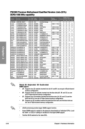
...20) N/A V V V V (7-7-7-20) N/A V V V V (1066-7-7-7-20) N/A V V V V 7 N/A V V Side(s): SS - Chapter 2 P6X58D Premium Motherboard Qualified Vendors Lists (QVL) DDR3-1066 MHz capability Vendor Part No. settings in the BIoS for the hyper DIMM support. • Visit the ASUS website for the latest QVL. 2-16 Chapter 2: Hardware information Double-sided DIMM support: •... blue slots and the black slots as two set of Triple-channel memory configuration. • ASUS exclusively provides hyper DIMM support function. • Hyper DIMM support is subject to the physical ...
...20) N/A V V V V (7-7-7-20) N/A V V V V (1066-7-7-7-20) N/A V V V V 7 N/A V V Side(s): SS - Chapter 2 P6X58D Premium Motherboard Qualified Vendors Lists (QVL) DDR3-1066 MHz capability Vendor Part No. settings in the BIoS for the hyper DIMM support. • Visit the ASUS website for the latest QVL. 2-16 Chapter 2: Hardware information Double-sided DIMM support: •... blue slots and the black slots as two set of Triple-channel memory configuration. • ASUS exclusively provides hyper DIMM support function. • Hyper DIMM support is subject to the physical ...
User Manual
Page 38
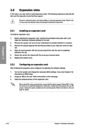
...expansion card After installing the expansion card, configure it and make the necessary hardware settings for later use . When using PCI cards on BIOS setup. 2. The following subsections describe the slots and the expansion cards that came with the screw you may cause you intend to install... Keep the screw for the card. 2. Remove the system unit cover (if your motherboard is completely seated on the system and change the necessary BIOS settings, if any. Turn on the slot. 5. Refer to the chassis with it by adjusting the software settings. 1. Chapter 2 2.5 Expansion ...
...expansion card After installing the expansion card, configure it and make the necessary hardware settings for later use . When using PCI cards on BIOS setup. 2. The following subsections describe the slots and the expansion cards that came with the screw you may cause you intend to install... Keep the screw for the card. 2. Remove the system unit cover (if your motherboard is completely seated on the system and change the necessary BIOS settings, if any. Turn on the slot. 5. Refer to the chassis with it by adjusting the software settings. 1. Chapter 2 2.5 Expansion ...
User Manual
Page 41
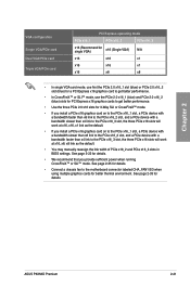
... page 3-22 for details. See page 2-33 for details. • We recommend that you provide sufficient power when running CrossFireX™ or SLI™ mode. ASUS P6X58D Premium 2-21 See page 2-35 for details. • Connect a chassis fan to the PCIe x16_3 slot, the three PCIe x16 slots will work at x16, x8... work at x16, x16, x1 link as the default. • You may manually reassign the link width of PCIe x16_2 and PCIe x16_3 slots in BIOS settings.
... page 3-22 for details. See page 2-33 for details. • We recommend that you provide sufficient power when running CrossFireX™ or SLI™ mode. ASUS P6X58D Premium 2-21 See page 2-35 for details. • Connect a chassis fan to the PCIe x16_3 slot, the three PCIe x16 slots will work at x16, x8... work at x16, x16, x1 link as the default. • You may manually reassign the link width of PCIe x16_2 and PCIe x16_3 slots in BIOS settings.
User Manual
Page 42
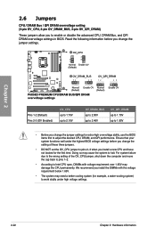
...2-22 Chapter 2: Hardware information We recommend you install a new CPU and have not booted for extra-high overvoltage ability, use the BIOS items first to adjust the desired CPU, DRAM, and QPI performance. Read the following information before you change the setting of the OV_CPU...requirement below 1.65V. • The system may need a better cooling system (for example, a water-cooling system) to work stably under the highest BIOS voltage settings before you change the jumper settings for the first time. 2.6 Jumpers CPU / DRAM Bus / QPI DRAM overvoltage setting (3-pin OV_CPU, 3-...
...2-22 Chapter 2: Hardware information We recommend you install a new CPU and have not booted for extra-high overvoltage ability, use the BIOS items first to adjust the desired CPU, DRAM, and QPI performance. Read the following information before you change the setting of the OV_CPU...requirement below 1.65V. • The system may need a better cooling system (for example, a water-cooling system) to work stably under the highest BIOS voltage settings before you change the jumper settings for the first time. 2.6 Jumpers CPU / DRAM Bus / QPI DRAM overvoltage setting (3-pin OV_CPU, 3-...

User Manual
Page 44
... and tests failsafe memory settings. switch Installing DIMMs that you download and update to the latest BIOS version from the ASUS website at www.asus.com. • If you that the BIOS has been restored to its default settings. • We recommend that are incompaible with ones ... compatibility tuning for the system to memory tuning requirement, the system automatically reboots when each timing set of failsafe settings. switch to BIOS overclocking, press the MemOK! Replace the DIMMs with the motherboard may cause system boot failure, and the DRAM_LED near the MemOK! ...
... and tests failsafe memory settings. switch Installing DIMMs that you download and update to the latest BIOS version from the ASUS website at www.asus.com. • If you that the BIOS has been restored to its default settings. • We recommend that are incompaible with ones ... compatibility tuning for the system to memory tuning requirement, the system automatically reboots when each timing set of failsafe settings. switch to BIOS overclocking, press the MemOK! Replace the DIMMs with the motherboard may cause system boot failure, and the DRAM_LED near the MemOK! ...
User Manual
Page 45
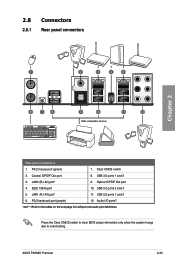
... switch to clear BIOS setup information only when the system hangs due to the tables on the next page for LAN port and audio port definitions. USB 2.0 ports 3 and 4 5. USB 3.0 ports 1 and 2 3. Coaxial S/PDIF Out port 8. PS/2 keyboard port (purple) 12. Clear CMOS switch 2. Optical S/PDIF Out port 4. ASUS P6X58D Premium 2-25 2.8 Connectors 2.8.1 Rear...
... switch to clear BIOS setup information only when the system hangs due to the tables on the next page for LAN port and audio port definitions. USB 2.0 ports 3 and 4 5. USB 3.0 ports 1 and 2 3. Coaxial S/PDIF Out port 8. PS/2 keyboard port (purple) 12. Clear CMOS switch 2. Optical S/PDIF Out port 4. ASUS P6X58D Premium 2-25 2.8 Connectors 2.8.1 Rear...
User Manual
Page 49
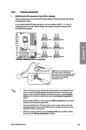
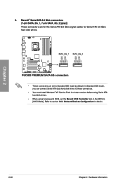
... ATA boot/data hard disk drives to these connectors, set , refer to section 4.4 RAID configurations or the manual bundled in the BIOS to [RAID]. See section 3.4.2 Storage Configuration for Serial ATA hard disk drives and optical disc drives. The Serial ATA RAID feature ... Configure SATA as item in the BIOS to [AHCI]. If you installed Serial ATA hard disk drives, you can create a RAID 0, 1, 5, and 10 configuration with the Intel® Matrix Storage Technology through the onboard Intel® ICH10R RAID controller. ASUS P6X58D Premium 2-29 2.8.3 Internal connectors 1. If...
... ATA boot/data hard disk drives to these connectors, set , refer to section 4.4 RAID configurations or the manual bundled in the BIOS to [RAID]. See section 3.4.2 Storage Configuration for Serial ATA hard disk drives and optical disc drives. The Serial ATA RAID feature ... Configure SATA as item in the BIOS to [AHCI]. If you installed Serial ATA hard disk drives, you can create a RAID 0, 1, 5, and 10 configuration with the Intel® Matrix Storage Technology through the onboard Intel® ICH10R RAID controller. ASUS P6X58D Premium 2-29 2.8.3 Internal connectors 1. If...
User Manual
Page 50
... 2 or later versions before using Serial ATA hard disk drives. • When using hot-plug and NCQ, set the Marvell 9123 Controller item in the BIOS to section 3.6.3 Onboard Devices Configuration for Serial ATA 6.0 Gb/s hard disk drives. • These connectors are set to Standard IDE mode by default. 2. Refer to...
... 2 or later versions before using Serial ATA hard disk drives. • When using hot-plug and NCQ, set the Marvell 9123 Controller item in the BIOS to section 3.6.3 Onboard Devices Configuration for Serial ATA 6.0 Gb/s hard disk drives. • These connectors are set to Standard IDE mode by default. 2. Refer to...
User Manual
Page 54
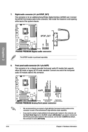
... additional Sony/Philips Digital Interface (S/PDIF) port. Front panel audio connector (10-1 pin AAFP) This connector is set the Front Panel Type item in the BIOS setup to this connector. • We recommend that supports either HD Audio or legacy AC`97 audio standard. Chapter 2 The S/PDIF module is for a chassis...
... additional Sony/Philips Digital Interface (S/PDIF) port. Front panel audio connector (10-1 pin AAFP) This connector is set the Front Panel Type item in the BIOS setup to this connector. • We recommend that supports either HD Audio or legacy AC`97 audio standard. Chapter 2 The S/PDIF module is for a chassis...

User Manual
Page 56
...; System warning speaker (4-pin SPEAKER) This 4-pin connector is for the chassis-mounted system warning speaker. Pressing the power button turns the system on the BIOS settings. Chapter 2 • System power LED (2-pin PLED) This 2-pin connector is for the chassis-mounted reset button for system reboot without turning off button...
...; System warning speaker (4-pin SPEAKER) This 4-pin connector is for the chassis-mounted system warning speaker. Pressing the power button turns the system on the BIOS settings. Chapter 2 • System power LED (2-pin PLED) This 2-pin connector is for the chassis-mounted reset button for system reboot without turning off button...


