
User Manual
Page 23
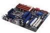
...RAM (3-pin CLRTC) 10. System panel connector (20-8 pin PANEL) 11. IEEE 1394a port connector (10-1 pin IE1394_2) 14. Digital audio connector (4-1 pin SPDIF_OUT) Page 2-33 2-5 2-10 2-22 2-1 2-32 2-29 2-28 2-21 2-34 2-31 2-30 2-31 2-30 2-27 2-27 Chapter 2 ASUS P6T SE... 2-3 DDR3 DIMM slots 4. USB connectors (10-1 pin USB78, USB910, USB1112) 13. Front panel audio connector (10-1 pin AAFP) 16. LGA1366 CPU Socket 3. 2.2.2 Layout contents Connectors/Jumpers/Slots 1. ICH10R Serial ATA connectors (7-pin SATA1-6) 8. ATX power connectors ...
...RAM (3-pin CLRTC) 10. System panel connector (20-8 pin PANEL) 11. IEEE 1394a port connector (10-1 pin IE1394_2) 14. Digital audio connector (4-1 pin SPDIF_OUT) Page 2-33 2-5 2-10 2-22 2-1 2-32 2-29 2-28 2-21 2-34 2-31 2-30 2-31 2-30 2-27 2-27 Chapter 2 ASUS P6T SE... 2-3 DDR3 DIMM slots 4. USB connectors (10-1 pin USB78, USB910, USB1112) 13. Front panel audio connector (10-1 pin AAFP) 16. LGA1366 CPU Socket 3. 2.2.2 Layout contents Connectors/Jumpers/Slots 1. ICH10R Serial ATA connectors (7-pin SATA1-6) 8. ATX power connectors ...

User Manual
Page 41
... re-enter data. Shut down the key during the boot process and enter BIOS setup to pins 1-2. 3. Chapter 2 To erase the RTC RAM 1. For system failure due to pins 2-3. Plug the power cord and turn off is required to the chipset behavior, AC power off and ... reset parameter settings to default values. • Due to enable C.P.R. You must turn ON the computer. 4. ASUS P6T SE 2-21 function. Keep the cap on CLRTC jumper default position. Clear RTC RAM (3-pin CLRTC) This jumper allows you to overclocking. Turn OFF the computer and unplug the power cord. 2. Move...
... re-enter data. Shut down the key during the boot process and enter BIOS setup to pins 1-2. 3. Chapter 2 To erase the RTC RAM 1. For system failure due to pins 2-3. Plug the power cord and turn off is required to the chipset behavior, AC power off and ... reset parameter settings to default values. • Due to enable C.P.R. You must turn ON the computer. 4. ASUS P6T SE 2-21 function. Keep the cap on CLRTC jumper default position. Clear RTC RAM (3-pin CLRTC) This jumper allows you to overclocking. Turn OFF the computer and unplug the power cord. 2. Move...

User Manual
Page 85
... Check [Full Access] [Setup] to change the user password. Change User Password Select this item to set or change password. Chapter 3 ASUS P6T SE 3-29 After you set a password, this item shows Installed. The message Password Installed appears after you can clear clear it by erasing the... CMOS Real Time Clock (RTC) RAM. After you have set a supervisor password, the other security settings. User Access Level [Full Access] This item allows you to change the...
... Check [Full Access] [Setup] to change the user password. Change User Password Select this item to set or change password. Chapter 3 ASUS P6T SE 3-29 After you set a password, this item shows Installed. The message Password Installed appears after you can clear clear it by erasing the... CMOS Real Time Clock (RTC) RAM. After you have set a supervisor password, the other security settings. User Access Level [Full Access] This item allows you to change the...

User Manual
Page 90
... the Exit menu to ensure the values you selected are finished making your selections, choose this menu or from the legend bar to the CMOS RAM. After selecting this option or if you press , a confirmation window appears. Load Setup Defaults This option allows you to save the changes while... Changes Select this operation. ←→ Select Screen ↑↓ Select Item Enter Go to the Setup program. Select Ok to the non-volatile RAM. Select Exit & Save Changes or make other than System Date, System Time, and Password, the BIOS asks for this option only if you are ...
... the Exit menu to ensure the values you selected are finished making your selections, choose this menu or from the legend bar to the CMOS RAM. After selecting this option or if you press , a confirmation window appears. Load Setup Defaults This option allows you to save the changes while... Changes Select this operation. ←→ Select Screen ↑↓ Select Item Enter Go to the Setup program. Select Ok to the non-volatile RAM. Select Exit & Save Changes or make other than System Date, System Time, and Password, the BIOS asks for this option only if you are ...


