
User Manual
Page 3
...iii Notices ...vii Safety information...viii About this guide...ix P6T SE specifications summary xi Chapter 1: Product introduction 1.1 Welcome!...1-1 1.2 Package contents 1-1 1.3 Special features 1-2 1.3.1 Product highlights 1-2 1.3.2 ASUS Unique features 1-2 Chapter 2: Hardware information 2.1 Before you proceed 2-1 2.2 Motherboard overview 2-2 2.2.1 Motherboard layout 2-2 2.2.2 Layout contents 2-3 2.2.3 Placement direction 2-4... Express x1 slot 2-19 2.5.6 PCI Express 2.0 x16 slots 2-19 2.6 Jumpers...2-21 2.7 Connectors 2-23 2.7.1 Rear panel connectors 2-23 iii
...iii Notices ...vii Safety information...viii About this guide...ix P6T SE specifications summary xi Chapter 1: Product introduction 1.1 Welcome!...1-1 1.2 Package contents 1-1 1.3 Special features 1-2 1.3.1 Product highlights 1-2 1.3.2 ASUS Unique features 1-2 Chapter 2: Hardware information 2.1 Before you proceed 2-1 2.2 Motherboard overview 2-2 2.2.1 Motherboard layout 2-2 2.2.2 Layout contents 2-3 2.2.3 Placement direction 2-4... Express x1 slot 2-19 2.5.6 PCI Express 2.0 x16 slots 2-19 2.6 Jumpers...2-21 2.7 Connectors 2-23 2.7.1 Rear panel connectors 2-23 iii

User Manual
Page 9
...of the BIOS parameters are not part of the switches, jumpers, and connectors on ASUS hardware and software products. ix It includes description of the standard package. ASUS websites The ASUS website provides updated information on the motherboard. • Chapter 3: BIOS setup This chapter tells how...change system settings through the BIOS Setup menus. Refer to the ASUS contact information. 2. These documents are also provided. • Chapter 4: Software support This chapter describes the contents of the motherboard and the new technology it supports. • Chapter 2: ...
...of the BIOS parameters are not part of the switches, jumpers, and connectors on ASUS hardware and software products. ix It includes description of the standard package. ASUS websites The ASUS website provides updated information on the motherboard. • Chapter 3: BIOS setup This chapter tells how...change system settings through the BIOS Setup menus. Refer to the ASUS contact information. 2. These documents are also provided. • Chapter 4: Software support This chapter describes the contents of the motherboard and the new technology it supports. • Chapter 2: ...

User Manual
Page 23
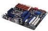
... 2-5 2-10 2-22 2-1 2-32 2-29 2-28 2-21 2-34 2-31 2-30 2-31 2-30 2-27 2-27 Chapter 2 ASUS P6T SE 2-3 Optical drive audio connector (4-pin CD) 15. Clear RTC RAM (3-pin CLRTC) 10. Onboard Power-on switch 6. 2.2.2 Layout contents Connectors/Jumpers/Slots 1. ATX power connectors (24-pin EATXPWR, 8-pin EATX12V) 2. USB connectors (10-1 pin USB78, USB910, USB1112) 13.
... 2-5 2-10 2-22 2-1 2-32 2-29 2-28 2-21 2-34 2-31 2-30 2-31 2-30 2-27 2-27 Chapter 2 ASUS P6T SE 2-3 Optical drive audio connector (4-pin CD) 15. Clear RTC RAM (3-pin CLRTC) 10. Onboard Power-on switch 6. 2.2.2 Layout contents Connectors/Jumpers/Slots 1. ATX power connectors (24-pin EATXPWR, 8-pin EATX12V) 2. USB connectors (10-1 pin USB78, USB910, USB1112) 13.

User Manual
Page 41
...the BIOS can clear the CMOS memory of date, time, and system setup parameters by erasing the CMOS RTC RAM data. ASUS P6T SE 2-21 Clear RTC RAM (3-pin CLRTC) This jumper allows you to enable C.P.R. Chapter 2 To erase the RTC RAM 1. Except when clearing the RTC RAM, never remove ...and enter BIOS setup to overclocking. function. You must turn ON the computer. 4. Turn OFF the computer and unplug the power cord. 2. Move the jumper cap from pins 1-2 (default) to overclocking, use the C.P.R. (CPU Parameter Recall) feature. The onboard button cell battery powers the RAM data in CMOS...
...the BIOS can clear the CMOS memory of date, time, and system setup parameters by erasing the CMOS RTC RAM data. ASUS P6T SE 2-21 Clear RTC RAM (3-pin CLRTC) This jumper allows you to enable C.P.R. Chapter 2 To erase the RTC RAM 1. Except when clearing the RTC RAM, never remove ...and enter BIOS setup to overclocking. function. You must turn ON the computer. 4. Turn OFF the computer and unplug the power cord. 2. Move the jumper cap from pins 1-2 (default) to overclocking, use the C.P.R. (CPU Parameter Recall) feature. The onboard button cell battery powers the RAM data in CMOS...

User Manual
Page 42
... items first to adjust the desired CPU, DRAM, and QPI performance. Read the following information before you change the setting of the OV_CPU jumper, shut down the computer and move the cap back to pins 1-2. • According to Intel CPU spec, DIMMs with the voltage requirement...example, a water-cooling system) to halt. CPU / DRAM Bus / QPI DRAM overvoltage setting (3-pin OV_CPU, 3-pin OV_DRAM_BUS, 3-pin OV_QPI_DRAM) These jumpers allow you install the DIMMs with voltage requirement over 1.65V may damage the CPU permanently. Doing so may need a better cooling system (for the ...
... items first to adjust the desired CPU, DRAM, and QPI performance. Read the following information before you change the setting of the OV_CPU jumper, shut down the computer and move the cap back to pins 1-2. • According to Intel CPU spec, DIMMs with the voltage requirement...example, a water-cooling system) to halt. CPU / DRAM Bus / QPI DRAM overvoltage setting (3-pin OV_CPU, 3-pin OV_DRAM_BUS, 3-pin OV_QPI_DRAM) These jumpers allow you install the DIMMs with voltage requirement over 1.65V may damage the CPU permanently. Doing so may need a better cooling system (for the ...

User Manual
Page 48
Chapter 2 Single device Two devices Drive jumper setting Cable-Select or Master Cable-Select Master Slave Mode of the following modes to configure your device. 3. IDE connector (40-1 pin PRI_IDE) The onboard .... There are three connectors on the IDE connector is set as "Cable-Select", ensure that all other device jumpers have the same setting. 2-28 Chapter 2: Hardware information If any device jumper is removed to the motherboard's IDE connector, then select one of device(s) Master Slave Master Slave Cable connector Black Black Gray Black...
Chapter 2 Single device Two devices Drive jumper setting Cable-Select or Master Cable-Select Master Slave Mode of the following modes to configure your device. 3. IDE connector (40-1 pin PRI_IDE) The onboard .... There are three connectors on the IDE connector is set as "Cable-Select", ensure that all other device jumpers have the same setting. 2-28 Chapter 2: Hardware information If any device jumper is removed to the motherboard's IDE connector, then select one of device(s) Master Slave Master Slave Cable connector Black Black Gray Black...

User Manual
Page 51
.... Doing so will damage the motherboard! 8. Chapter 2 7. Connect one end of the system chassis. Connect the IEEE 1394a module cable to this connector when a chassis component is for a chassis-mounted intrusion detection sensor or switch. ASUS P6T SE 2-31 Chassis intrusion connector (4-1 ...pin CHASSIS) This connector is then generated as a chassis intrusion event. The signal is for an IEEE 1394a port. Remove the jumper caps only when you intend to a slot...
.... Doing so will damage the motherboard! 8. Chapter 2 7. Connect one end of the system chassis. Connect the IEEE 1394a module cable to this connector when a chassis component is for a chassis-mounted intrusion detection sensor or switch. ASUS P6T SE 2-31 Chassis intrusion connector (4-1 ...pin CHASSIS) This connector is then generated as a chassis intrusion event. The signal is for an IEEE 1394a port. Remove the jumper caps only when you intend to a slot...

User Manual
Page 52
... on the fan connectors! • Only the CPU_FAN, CHA_FAN 1 and CHA_FAN 2 connectors support the ASUS Q FAN 2 feature. • If you plug the rear chassis fan cable to the fan connectors. Do not place jumper caps on the motherboard, making sure that you install two VGA cards, we recommend that the black wire of...
... on the fan connectors! • Only the CPU_FAN, CHA_FAN 1 and CHA_FAN 2 connectors support the ASUS Q FAN 2 feature. • If you plug the rear chassis fan cable to the fan connectors. Do not place jumper caps on the motherboard, making sure that you install two VGA cards, we recommend that the black wire of...

User Manual
Page 56
...green after the system LED turns on self tests or POST. If your retailer for the first time 1. Check the jumper settings and connections or call your monitor complies with ATX power supplies, the system LED lights up when you turned on the power, the system may light up or change ...from the time you press the ATX power button. Monitor b. The system then runs the power-on . Pressing the power switch for details. 2-36 Chapter 2: Hardware information After making all ...
...green after the system LED turns on self tests or POST. If your retailer for the first time 1. Check the jumper settings and connections or call your monitor complies with ATX power supplies, the system LED lights up when you turned on the power, the system may light up or change ...from the time you press the ATX power button. Monitor b. The system then runs the power-on . Pressing the power switch for details. 2-36 Chapter 2: Hardware information After making all ...

User Manual
Page 62
...screens shown in this last option only if the first two failed. Select the Load Setup Defaults item under the Exit menu. See section 2.6 Jumpers for details. • If the system fails to boot after changing any BIOS setting, load the default settings to enter Setup after changing ...any BIOS setting, try to clear the CMOS and reset the motherboard to run this program. See section 3.10 Exit Menu for details. 3.3.1 BIOS menu screen Menu items Menu bar Configuration fields General help BIOS...
...screens shown in this last option only if the first two failed. Select the Load Setup Defaults item under the Exit menu. See section 2.6 Jumpers for details. • If the system fails to boot after changing any BIOS setting, load the default settings to enter Setup after changing ...any BIOS setting, try to clear the CMOS and reset the motherboard to run this program. See section 3.10 Exit Menu for details. 3.3.1 BIOS menu screen Menu items Menu bar Configuration fields General help BIOS...

User Manual
Page 72
...also use the and keys to 2.50V with a 0.02V interval. The value [1.90000V] of the CPU Voltage item is supported only if the OV_CPU jumper is enabled. The values range from 1.10V to 1.70V with a 0.00625V interval. • Refer to the CPU documentation before setting the CPU Vcore ... VCore voltage may make the system unstable. • The value [2.10000V] of the QPI/DRAM Core Voltage item is supported only if the OV_ QPI_DRAM jumper is enabled. Otherwise the maximum voltage supported is [1.70000V]. The values range from 0.85000V to 2.10000V* with a 0.02V interval. 3.5.11 IOH PCIE ...
...also use the and keys to 2.50V with a 0.02V interval. The value [1.90000V] of the CPU Voltage item is supported only if the OV_CPU jumper is enabled. The values range from 1.10V to 1.70V with a 0.00625V interval. • Refer to the CPU documentation before setting the CPU Vcore ... VCore voltage may make the system unstable. • The value [2.10000V] of the QPI/DRAM Core Voltage item is supported only if the OV_ QPI_DRAM jumper is enabled. Otherwise the maximum voltage supported is [1.70000V]. The values range from 0.85000V to 2.10000V* with a 0.02V interval. 3.5.11 IOH PCIE ...

User Manual
Page 73
...Voltage items are labeled in different color, indicating the risk levels of the DRAM Bus Voltage item is supported only if the OV_DRAM_ BUS jumper is enabled, otherwise the maximum voltage supported is [1.90V]. The values range from 1.50V to 1.80V with voltage requirement over 1.65V ... settings. CPU / DRAM Bus / QPI DRAM overvoltage setting on page 2-22 for details. • The system may damage the CPU permanently. Chapter 3 ASUS P6T SE 3-17 3.5.12 ICH Voltage [Auto] Allows you to set the DRAM DATA Reference Voltage on Channel A/B/C. The values range from 1.50V to 2.46V* with...
...Voltage items are labeled in different color, indicating the risk levels of the DRAM Bus Voltage item is supported only if the OV_DRAM_ BUS jumper is enabled, otherwise the maximum voltage supported is [1.90V]. The values range from 1.50V to 1.80V with voltage requirement over 1.65V ... settings. CPU / DRAM Bus / QPI DRAM overvoltage setting on page 2-22 for details. • The system may damage the CPU permanently. Chapter 3 ASUS P6T SE 3-17 3.5.12 ICH Voltage [Auto] Allows you to set the DRAM DATA Reference Voltage on Channel A/B/C. The values range from 1.50V to 2.46V* with...

User Manual
Page 85
... six letters and/or numbers, then press . 3. again to erase the RTC RAM. Chapter 3 ASUS P6T SE 3-29 Select the Change Supervisor Password item and press . 2. To clear the supervisor password, select the Change Supervisor Password then press . See section 2.6 Jumpers for information on how to disabled password. After you to set your password.
... six letters and/or numbers, then press . 3. again to erase the RTC RAM. Chapter 3 ASUS P6T SE 3-29 Select the Change Supervisor Password item and press . 2. To clear the supervisor password, select the Change Supervisor Password then press . See section 2.6 Jumpers for information on how to disabled password. After you to set your password.

