User Manual
Page 4
... SCSI Devices 31 SCSI ID Priority 31 V. FEATURES 8 Parts of the ASUS P/I-P65UP5 Baseboard 8 II. INSTALLATION 10 ASUS Baseboard Layout 10 Installation Steps 12 1. External Connectors 22 IV. CONTENTS I -P65UP5 User's Manual Jumpers 12 Jumper Settings 13 2. ASUS I-A16C Audio Card 32 ASUS I-A16C Audio Features 32 Layout and Connectors 32 Connectors 32 CD-Audio Connector Pin Definitions 32 4 ASUS P/I . System Memory (DRAM/SDRAM & SRAM 16 DRAM Memory Installation Procedures 17 3. ASUS PCI SCSI Cards 28 Symbios SCSI BIOS and Drivers 28 ASUS PCI-SC200 & PCI-SC860...
... SCSI Devices 31 SCSI ID Priority 31 V. FEATURES 8 Parts of the ASUS P/I-P65UP5 Baseboard 8 II. INSTALLATION 10 ASUS Baseboard Layout 10 Installation Steps 12 1. External Connectors 22 IV. CONTENTS I -P65UP5 User's Manual Jumpers 12 Jumper Settings 13 2. ASUS I-A16C Audio Card 32 ASUS I-A16C Audio Features 32 Layout and Connectors 32 Connectors 32 CD-Audio Connector Pin Definitions 32 4 ASUS P/I . System Memory (DRAM/SDRAM & SRAM 16 DRAM Memory Installation Procedures 17 3. ASUS PCI SCSI Cards 28 Symbios SCSI BIOS and Drivers 28 ASUS PCI-SC200 & PCI-SC860...
User Manual
Page 6
... radiate radio frequency energy and, if not installed and used in the Radio Interference Regulations of the Canadian Department of the monitor to the graphics card is subject to radio communications. If this unit not expressly approved by turning the equipment off and on a circuit different from digital apparatus set out in accordance with FCC Rules Part 15. Changes or...
... radiate radio frequency energy and, if not installed and used in the Radio Interference Regulations of the Canadian Department of the monitor to the graphics card is subject to radio communications. If this unit not expressly approved by turning the equipment off and on a circuit different from digital apparatus set out in accordance with FCC Rules Part 15. Changes or...
User Manual
Page 7
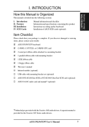
...I -A16C audio card and manual* (optional) *Online help is complete. ASUS P/I-P65UP5 baseboard C-P6ND, C-P55T2D, or C-PKND CPU card 2 serial port ribbon cables attached to a mounting bracket 1 parallel ribbon cable with mounting bracket 1 IDE ribbon cable 1 floppy ribbon cable This user's manual Infrared module (optional) USB cable with the Creative 16X audio drivers. A separate manual is divided into the following sections: I . Features: III. Installation: IV. I . SCSI Cards: Manual information and checklist Information and specifications concerning this Manual is Organized...
...I -A16C audio card and manual* (optional) *Online help is complete. ASUS P/I-P65UP5 baseboard C-P6ND, C-P55T2D, or C-PKND CPU card 2 serial port ribbon cables attached to a mounting bracket 1 parallel ribbon cable with mounting bracket 1 IDE ribbon cable 1 floppy ribbon cable This user's manual Infrared module (optional) USB cable with the Creative 16X audio drivers. A separate manual is divided into the following sections: I . Features: III. Installation: IV. I . SCSI Cards: Manual information and checklist Information and specifications concerning this Manual is Organized...
User Manual
Page 8
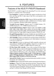
... a memory size between 8MB to make setup of hard drives and expansion cards virtually automatic. • Desktop Management Interface (DMI): Supports DMI through the optional onboard LM78 Hardware Monitor and Intel® LANDesk Client Manager (LDCM) software. 8 ASUS P/I -P65UP5 is carefully designed for the demanding PC user who wants great versatility in two channels, supports PIO Modes 3 and 4 and Bus Master IDE DMA Mode 2, and supports Enhanced IDE devices such as Tape Backup and CD-ROM drives. BIOS supports IDE...
... a memory size between 8MB to make setup of hard drives and expansion cards virtually automatic. • Desktop Management Interface (DMI): Supports DMI through the optional onboard LM78 Hardware Monitor and Intel® LANDesk Client Manager (LDCM) software. 8 ASUS P/I -P65UP5 is carefully designed for the demanding PC user who wants great versatility in two channels, supports PIO Modes 3 and 4 and Bus Master IDE DMA Mode 2, and supports Enhanced IDE devices such as Tape Backup and CD-ROM drives. BIOS supports IDE...
User Manual
Page 10
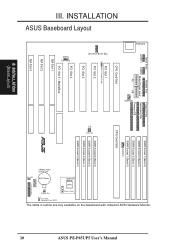
...RAM Operation/Clear CMOS IDE LED 10 III. ASUS P/I-P65UP5 User's Manual The items in outline are only available on the baseboard with onboard LM78 Hardware Monitor. INSTALLATION ASUS Baseboard Layout Serial Ports Parallel Port COM 1 COM 2 Board Power Input P9 P8 Floppy Drives Secondary IDE Primary IDE FANPWR1 CPU Card Slot SIMM Socket 7 (Bank 3) SIMM Socket 5 (Bank 2) SIMM Socket 3 (Bank 1) SIMM Socket 1 (Bank 0) FANPWR2 CPU Card Slot PCI Slot 1 Multi-i/O Enable/Disable PCI Slot 2 PCI Slot 3 PCI Slot 4 SIMM Socket 8 (Bank 3) BUS Freq. JP2 JP3 SIMM Socket 6 (Bank 2) SIMM Socket...
...RAM Operation/Clear CMOS IDE LED 10 III. ASUS P/I-P65UP5 User's Manual The items in outline are only available on the baseboard with onboard LM78 Hardware Monitor. INSTALLATION ASUS Baseboard Layout Serial Ports Parallel Port COM 1 COM 2 Board Power Input P9 P8 Floppy Drives Secondary IDE Primary IDE FANPWR1 CPU Card Slot SIMM Socket 7 (Bank 3) SIMM Socket 5 (Bank 2) SIMM Socket 3 (Bank 1) SIMM Socket 1 (Bank 0) FANPWR2 CPU Card Slot PCI Slot 1 Multi-i/O Enable/Disable PCI Slot 2 PCI Slot 3 PCI Slot 4 SIMM Socket 8 (Bank 3) BUS Freq. JP2 JP3 SIMM Socket 6 (Bank 2) SIMM Socket...
User Manual
Page 11
...) p. 26 Turbo LED Lead (2 pins) 10) SMI (CON1) p. 26 SMI Suspend Switch Lead (2 pins) 11) RESET (CON1) p. 26 Reset Switch Lead (2 pins) 12) PWR LED (CON1) p. 26 System Power LED Lead (3 pins) 13) KEYLOCK (CON1) p. 26 Keyboard Lock Switch Lead (2 pins) 14) SPEAKER (CON1) p. 26 Speaker Output Connector (4 pins) 15) FANPWR1,FANPWR2,FANPWR3 p. 27 Power Supply, CPU Fan Power Connectors 16) USB p. 27 USB Module Connector (18-pin block) 17) CHASSIS (optional) p. 27 Chassis Open Alarm Connector (3-pin block) ASUS P/I-P65UP5 User's Manual 11 INSTALLATION (Board Layout) III. III.
...) p. 26 Turbo LED Lead (2 pins) 10) SMI (CON1) p. 26 SMI Suspend Switch Lead (2 pins) 11) RESET (CON1) p. 26 Reset Switch Lead (2 pins) 12) PWR LED (CON1) p. 26 System Power LED Lead (3 pins) 13) KEYLOCK (CON1) p. 26 Keyboard Lock Switch Lead (2 pins) 14) SPEAKER (CON1) p. 26 Speaker Output Connector (4 pins) 15) FANPWR1,FANPWR2,FANPWR3 p. 27 Power Supply, CPU Fan Power Connectors 16) USB p. 27 USB Module Connector (18-pin block) 17) CHASSIS (optional) p. 27 Chassis Open Alarm Connector (3-pin block) ASUS P/I-P65UP5 User's Manual 11 INSTALLATION (Board Layout) III. III.
User Manual
Page 12
... jumpers may be moved together. Install DRAM Memory Modules 3. The jumper settings will be shown graphically such as for short (On) and for our baseboards is written be shown as to connect pins 1&2 and to connect jumper pins (JP) on your computer when working on jumpers with the keyboard connector away from the system. 12 ASUS P/I-P65UP5 User's Manual The jumpers will be - Computer motherboards, baseboards and components, such as diagramed. Unplug your computer. 1. Use...
... jumpers may be moved together. Install DRAM Memory Modules 3. The jumper settings will be shown graphically such as for short (On) and for our baseboards is written be shown as to connect pins 1&2 and to connect jumper pins (JP) on your computer when working on jumpers with the keyboard connector away from the system. 12 ASUS P/I-P65UP5 User's Manual The jumpers will be - Computer motherboards, baseboards and components, such as diagramed. Unplug your computer. 1. Use...
User Manual
Page 15
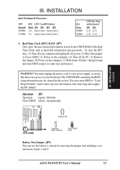
INSTALLATION (Jumpers) III. The CMOS RAM containing the BIOS setup information may be cleared by removing the jumper and attaching a current meter to re-enter user preferences. ASUS P/I-P65UP5 User's Manual 15 Freq. 66MHz 66MHz (CPU Ext. III. Real Time Clock (RTC) RAM (JP7) This clears the user-entered information stored in the CMOS RAM of the Real Time Clock such as hard disk information and passwords. You must unplug the power cord to your power supply to ensure that there...
INSTALLATION (Jumpers) III. The CMOS RAM containing the BIOS setup information may be cleared by removing the jumper and attaching a current meter to re-enter user preferences. ASUS P/I-P65UP5 User's Manual 15 Freq. 66MHz 66MHz (CPU Ext. III. Real Time Clock (RTC) RAM (JP7) This clears the user-entered information stored in the CMOS RAM of the Real Time Clock such as hard disk information and passwords. You must unplug the power cord to your power supply to ensure that there...
User Manual
Page 16
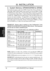
... size memory modules. Modules with C-P6ND only). INSTALLATION (Memory) III. The DRAM can be either 60ns or 70ns Fast Page Mode (Asymmetric or Symmetric), Extended Data Output (EDO), or Burst Extended Data Output (BEDO) (with more than 24 chips exceed the design specifications of 5.0 cm when the C-PKND and C-P6ND CPU cards are installed and 5.5 cm when the C-P55T2D CPU card is required in "Auto Configuration...
... size memory modules. Modules with C-P6ND only). INSTALLATION (Memory) III. The DRAM can be either 60ns or 70ns Fast Page Mode (Asymmetric or Symmetric), Extended Data Output (EDO), or Burst Extended Data Output (BEDO) (with more than 24 chips exceed the design specifications of 5.0 cm when the C-PKND and C-P6ND CPU cards are installed and 5.5 cm when the C-P55T2D CPU card is required in "Auto Configuration...
User Manual
Page 17
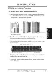
... the clips. ASUS P/I-P65UP5 User's Manual 17 The SIMM memory modules will only fit in SIMM Socket Safety Tab (This Side Only) Mounting Hole 4. III. Press the memory module firmly into place starting from a 45 degree angle making sure that it clicks into a vertical position so that all the contacts are aligned with the slot. 3. INSTALLATION DRAM Memory Installation Procedures IMPORTANT: Install memory modules in...
... the clips. ASUS P/I-P65UP5 User's Manual 17 The SIMM memory modules will only fit in SIMM Socket Safety Tab (This Side Only) Mounting Hole 4. III. Press the memory module firmly into place starting from a 45 degree angle making sure that it clicks into a vertical position so that all the contacts are aligned with the slot. 3. INSTALLATION DRAM Memory Installation Procedures IMPORTANT: Install memory modules in...
User Manual
Page 19
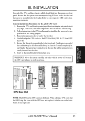
... the CPU cards are evenly inserted into the system case front panel. ASUS P/I-P65UP5 User's Manual 19 Refer to the baseboard. Follow instructions in the metal bracket to the system case. Be sure that a groove is heavy as well as delicate. Place it with the power off because the CPU card is available for details. INSTALLATION (CPU Card) R CPU Card Slot C-P55T2D C-P6ND C-PKND NOTE: The BIOS on installing the processor/s, support bracket, and setting jumpers. 3. INSTALLATION...
... the CPU cards are evenly inserted into the system case front panel. ASUS P/I-P65UP5 User's Manual 19 Refer to the baseboard. Follow instructions in the metal bracket to the system case. Be sure that a groove is heavy as well as delicate. Place it with the power off because the CPU card is available for details. INSTALLATION (CPU Card) R CPU Card Slot C-P55T2D C-P6ND C-PKND NOTE: The BIOS on installing the processor/s, support bracket, and setting jumpers. 3. INSTALLATION...
User Manual
Page 20
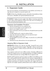
.... WARNING! Carefully align the card's connectors and press firmly. 6. Set up your specific card. Install the necessary software drivers for your expansion card. Generally an IRQ must be required to set up the BIOS if necessary (such as legacy ISA cards, requires that you configure the card's jumpers manually and then install it in any hardware and software settings that will arise on the ISA 20 ASUS P/I-P65UP5 User's Manual NOTE: PCI Slot 5 has a MediaBus extension...
.... WARNING! Carefully align the card's connectors and press firmly. 6. Set up your specific card. Install the necessary software drivers for your expansion card. Generally an IRQ must be required to set up the BIOS if necessary (such as legacy ISA cards, requires that you configure the card's jumpers manually and then install it in any hardware and software settings that will arise on the ISA 20 ASUS P/I-P65UP5 User's Manual NOTE: PCI Slot 5 has a MediaBus extension...
User Manual
Page 21
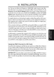
... icon under the Control Panel program). INSTALLATION (DMA Channels) III. If the system has both legacy and PnP, may also need to PnP cards from those available. You can be used by legacy cards. INSTALLATION bus. Since all the PCI slots on this baseboard use a DMA (Direct Memory Access) channel. For older legacy cards that do not work with the Plug and Play (PnP) specification, which IRQs are in the Windows directory to...
... icon under the Control Panel program). INSTALLATION (DMA Channels) III. If the system has both legacy and PnP, may also need to PnP cards from those available. You can be used by legacy cards. INSTALLATION bus. Since all the PCI slots on this baseboard use a DMA (Direct Memory Access) channel. For older legacy cards that do not work with the Plug and Play (PnP) specification, which IRQs are in the Windows directory to...

User Manual
Page 22
... are labeled on hard and floppy disk drives. Pin 1 is on page 10. Keyboard Connector (5-pin female) PS/2 Keyboard Port (CPU Card) R Connector Plug from the first connector. 1. Pin 1 Orient the red stripe on the floppy ribbon cable to the power connector on the baseboard. External Connectors WARNING! IMPORTANT: Connect ribbon cables such that the red stripe is the side closest to Pin 1 R Floppy Drive Connector 22 ASUS P/I-P65UP5 User's Manual Use either a standard IBM-compatible, 101/102-key, or 104key (Windows 95-compatible) keyboard. INSTALLATION (Connectors) III...
... are labeled on hard and floppy disk drives. Pin 1 is on page 10. Keyboard Connector (5-pin female) PS/2 Keyboard Port (CPU Card) R Connector Plug from the first connector. 1. Pin 1 Orient the red stripe on the floppy ribbon cable to the power connector on the baseboard. External Connectors WARNING! IMPORTANT: Connect ribbon cables such that the red stripe is the side closest to Pin 1 R Floppy Drive Connector 22 ASUS P/I-P65UP5 User's Manual Use either a standard IBM-compatible, 101/102-key, or 104key (Windows 95-compatible) keyboard. INSTALLATION (Connectors) III...

User Manual
Page 23
... IRQ Onboard Parallel Port in Chipset Features of the BIOS SOFTWARE. (Pin 10 is removed to prevent inserting in the wrong orientation when using ribbon cables with pin 10 plugged) Pin 1 Orient the red stripe on the serial ribbon cable to Pin 1 COM 1 Pin 1 COM 2 Serial Port Connectors For the serial port connectors to save expansion slot space. ASUS P/I-P65UP5 User's Manual 23 III. R R 4. Connect the ribbon cables to these connectors and mount the bracket to save expansion slot space. INSTALLATION (Connectors) III...
... IRQ Onboard Parallel Port in Chipset Features of the BIOS SOFTWARE. (Pin 10 is removed to prevent inserting in the wrong orientation when using ribbon cables with pin 10 plugged) Pin 1 Orient the red stripe on the serial ribbon cable to Pin 1 COM 1 Pin 1 COM 2 Serial Port Connectors For the serial port connectors to save expansion slot space. ASUS P/I-P65UP5 User's Manual 23 III. R R 4. Connect the ribbon cables to these connectors and mount the bracket to save expansion slot space. INSTALLATION (Connectors) III...
User Manual
Page 24
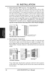
.... 24 ASUS P/I-P65UP5 User's Manual Pin 1 Orient the red stripe on the lead to prevent inserting in the BIOS FEATURES SETUP of the BIOS software). (Pin 20 is not plugged. III. A new BIOS feature allows SCSI hard drive bootup (see "HDD Sequence SCSI/IDE First" in the wrong orientation when using one connector (channel), then you must configure a second drive as Slave mode by setting its jumper according to your hard disk jumper diagram. Orient the connectors so that...
.... 24 ASUS P/I-P65UP5 User's Manual Pin 1 Orient the red stripe on the lead to prevent inserting in the BIOS FEATURES SETUP of the BIOS software). (Pin 20 is not plugged. III. A new BIOS feature allows SCSI hard drive bootup (see "HDD Sequence SCSI/IDE First" in the wrong orientation when using one connector (channel), then you must configure a second drive as Slave mode by setting its jumper according to your hard disk jumper diagram. Orient the connectors so that...
User Manual
Page 26
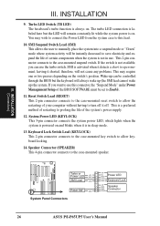
... GND Reset SW GND System Panel Connectors +5V NC Power LED GND LOCK GND Keyboard Lock +5V GND Speaker GND Connector SPKR 26 ASUS P/I-P65UP5 User's Manual Reset Switch Lead (RESET) This 2-pin connector connects to the case-mounted reset switch to use this lead. 10. If the switch is not in sleep mode. 13. This is in use the turbo switch. Wake-up ) the system. Turbo LED Switch (TB LED) The baseboard's turbo function is activated when it detects a short to...
... GND Reset SW GND System Panel Connectors +5V NC Power LED GND LOCK GND Keyboard Lock +5V GND Speaker GND Connector SPKR 26 ASUS P/I-P65UP5 User's Manual Reset Switch Lead (RESET) This 2-pin connector connects to the case-mounted reset switch to use this lead. 10. If the switch is not in sleep mode. 13. This is in use the turbo switch. Wake-up ) the system. Turbo LED Switch (TB LED) The baseboard's turbo function is activated when it detects a short to...
User Manual
Page 27
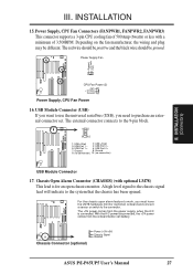
... USB Port 0 + 7: Ground 8: Ground 9: (no connection) 10: (no connection) USB Module Connector 17. INSTALLATION 15. USB Module Connector (USB) If you want to use the universal serial bus (USB), you must have the LM78 hardware monitor (optional) onboard and connect a sensor or switch to purchase an external connector set. The red wire should be positive and the black wire should be different. INSTALLATION (Connectors) R R R CPU Fan Power (2) (NC) +12 Volts Ground Power Supply, CPU Fan Power 16. Chassis Connector (optional) Power (+3V/+5V) Chassis Signal Ground ASUS P/I-P65UP5 User...
... USB Port 0 + 7: Ground 8: Ground 9: (no connection) 10: (no connection) USB Module Connector 17. INSTALLATION 15. USB Module Connector (USB) If you want to use the universal serial bus (USB), you must have the LM78 hardware monitor (optional) onboard and connect a sensor or switch to purchase an external connector set. The red wire should be positive and the black wire should be different. INSTALLATION (Connectors) R R R CPU Fan Power (2) (NC) +12 Volts Ground Power Supply, CPU Fan Power 16. Chassis Connector (optional) Power (+3V/+5V) Chassis Signal Ground ASUS P/I-P65UP5 User...
User Manual
Page 28
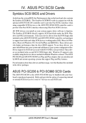
... the ASUS PCI-SC860 SCSI controller cards to support hard disks and other SCSI devices working under the DOS, Windows and OS/2 environments. For information about these drivers, you install on the baseboard also contains the Symbios SCSI BIOS. ASUS PCI-SC200 & PCI-SC860 SCSI Cards The ASUS PCI-SC200 or the ASUS PCI-SC860 may be bundled with your system configuration files. It also uses device drivers from the system BIOS, the Flash memory chip on your system require driver software...
... the ASUS PCI-SC860 SCSI controller cards to support hard disks and other SCSI devices working under the DOS, Windows and OS/2 environments. For information about these drivers, you install on the baseboard also contains the Symbios SCSI BIOS. ASUS PCI-SC200 & PCI-SC860 SCSI Cards The ASUS PCI-SC200 or the ASUS PCI-SC860 may be bundled with your system configuration files. It also uses device drivers from the system BIOS, the Flash memory chip on your system require driver software...
User Manual
Page 30
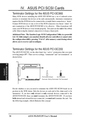
... SCSI Configuration Utility is a powerful tool. JP JP 5 5 Terminated (Default) Not Terminated Terminator Setting (Terminated / Not Terminated) Decide whether or not you must set of the ASUS PCI-SC860 to recover and reconfigure. ASUS SCSI Cards (Jumpers) 30 ASUS P/I-P65UP5 User's Manual ASUS PCI SCSI Cards Terminator Settings for auto termination of onboard active resistors to terminate the ASUS PCI-SC200 based on the other hand, has "active" termination that the SCSI devices be...
... SCSI Configuration Utility is a powerful tool. JP JP 5 5 Terminated (Default) Not Terminated Terminator Setting (Terminated / Not Terminated) Decide whether or not you must set of the ASUS PCI-SC860 to recover and reconfigure. ASUS SCSI Cards (Jumpers) 30 ASUS P/I-P65UP5 User's Manual ASUS PCI SCSI Cards Terminator Settings for auto termination of onboard active resistors to terminate the ASUS PCI-SC200 based on the other hand, has "active" termination that the SCSI devices be...


