
Motherboard Installation Guide
Page 17
... Launcher User guide If any of ASUS quality motherboards! 1.1 Welcome! Before you for up to 7 devices I /O modules Cables Accessories Application CD Documentation ASUS P5W64 WS PRO motherboard 1 x 2-port IEEE 1394a module 1 x 2-port USB 2.0 module 1 x Floppy disk drive cable 1 x Ultra DMA 133/100/66 cable 7 x Serial ATA signal cables 4 x Serial ATA power cables for buying an ASUS® P5W64 WS Professional Workstation motherboard!
... Launcher User guide If any of ASUS quality motherboards! 1.1 Welcome! Before you for up to 7 devices I /O modules Cables Accessories Application CD Documentation ASUS P5W64 WS PRO motherboard 1 x 2-port IEEE 1394a module 1 x 2-port USB 2.0 module 1 x Floppy disk drive cable 1 x Ultra DMA 133/100/66 cable 7 x Serial ATA signal cables 4 x Serial ATA power cables for buying an ASUS® P5W64 WS Professional Workstation motherboard!
Motherboard Installation Guide
Page 27
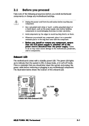
... bag that came with a standby power LED. 2.1 Before you proceed Take note of the onboard LED. ® P5W64 WS PRO SB_PWR ON Standby Power P5W64 WS PRO Onboard LED OFF Powered Off ASUS P5W64 WS Professional 2-1 The green LED lights up to the motherboard, peripherals, and/or components. The illustration below shows the location of the following precautions before you install...
... bag that came with a standby power LED. 2.1 Before you proceed Take note of the onboard LED. ® P5W64 WS PRO SB_PWR ON Standby Power P5W64 WS PRO Onboard LED OFF Powered Off ASUS P5W64 WS Professional 2-1 The green LED lights up to the motherboard, peripherals, and/or components. The illustration below shows the location of the following precautions before you install...
Motherboard Installation Guide
Page 28
... indicated by circles to secure the motherboard to unplug the power cord before installing or removing the motherboard. Do not overtighten the screws! Failure to do so can damage the motherboard. Make sure to the chassis. 2.2 Motherboard overview Before you place it into ...indicated in the correct orientation. Doing so can cause you physical injury and damage motherboard components. 2.2.1 Placement direction When installing the motherboard, make sure that you install the motherboard, study the configuration of the chassis ® P5W64 WS PRO 2-2 Chapter 2: Hardware information
... indicated by circles to secure the motherboard to unplug the power cord before installing or removing the motherboard. Do not overtighten the screws! Failure to do so can damage the motherboard. Make sure to the chassis. 2.2 Motherboard overview Before you place it into ...indicated in the correct orientation. Doing so can cause you physical injury and damage motherboard components. 2.2.1 Placement direction When installing the motherboard, make sure that you install the motherboard, study the configuration of the chassis ® P5W64 WS PRO 2-2 Chapter 2: Hardware information
Motherboard Installation Guide
Page 30
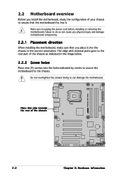
30.5cm (12.0in) 2.2.4 Motherboard layout 24.5cm (9.6in) PS/2KBMS T: Mouse B: Keyboard SPDIF_O1 SPDIF_O2 EATX12V LGA775 CPU_FAN PWR_FAN Super I/O ESATA PARALLEL PORT FLOPPY DDR2 DIMM_B1 (64 bit,240-pin module) DDR2 DIMM_B2 (64 bit,240-pin module) ® P5W64 WS PRO DDR2 DIMM_A1 (64 bit,240-pin module) DDR2 DIMM_A2 (64 bit,240-pin...
30.5cm (12.0in) 2.2.4 Motherboard layout 24.5cm (9.6in) PS/2KBMS T: Mouse B: Keyboard SPDIF_O1 SPDIF_O2 EATX12V LGA775 CPU_FAN PWR_FAN Super I/O ESATA PARALLEL PORT FLOPPY DDR2 DIMM_B1 (64 bit,240-pin module) DDR2 DIMM_B2 (64 bit,240-pin module) ® P5W64 WS PRO DDR2 DIMM_A1 (64 bit,240-pin module) DDR2 DIMM_A2 (64 bit,240-pin...

Motherboard Installation Guide
Page 34
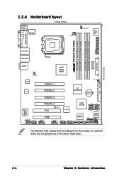
... the arrow to the left . 2. Lift the load lever in the direction of the socket box should face you. Locate the CPU socket on the motherboard. ® P5W64 WS PRO P5W64 WS PRO CPU Socket 775 Before installing the CPU, make sure that the socket box is released from the retention tab.
... the arrow to the left . 2. Lift the load lever in the direction of the socket box should face you. Locate the CPU socket on the motherboard. ® P5W64 WS PRO P5W64 WS PRO CPU Socket 775 Before installing the CPU, make sure that the socket box is released from the retention tab.

Motherboard Installation Guide
Page 37
Hardware monitoring errors can occur if you fail to the connector on the motherboard labeled CPU_FAN. 2. ASUS P5W64 WS Professional 2-11 A B A B A B B A 3. Connect the CPU fan cable to plug this connector. CPU_FAN ® P5W64 WS PRO CPU FAN PWM CPU FAN IN CPU FAN PWR GND P5W64 WS PRO CPU fan connector Do not forget to secure the heatsink and fan assembly in place. Push down two fasteners at a time in a diagonal sequence to connect the CPU fan connector!
Hardware monitoring errors can occur if you fail to the connector on the motherboard labeled CPU_FAN. 2. ASUS P5W64 WS Professional 2-11 A B A B A B B A 3. Connect the CPU fan cable to plug this connector. CPU_FAN ® P5W64 WS PRO CPU FAN PWM CPU FAN IN CPU FAN PWR GND P5W64 WS PRO CPU fan connector Do not forget to secure the heatsink and fan assembly in place. Push down two fasteners at a time in a diagonal sequence to connect the CPU fan connector!
Motherboard Installation Guide
Page 40
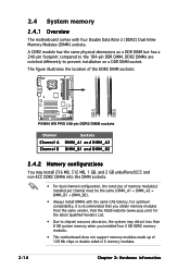
...with the same CAS latency. For optimum compatibility, it is recommended that you installed four 2 GB DDR2 memory modules. • This motherboard does not support memory modules made up of memory module(s) installed per channel must be the same (DIMM_A1 + DIMM_A2 = DIMM_B1 + ... DIMM_A2 DIMM_B1 DIMM_B2 P5W64 WS PRO 240-pin DDR2 DIMM sockets Channel Channel A Channel B Sockets DIMM_A1 and DIMM_A2 DIMM_B1 and DIMM_B2 2.4.2 Memory configurations You may detect less than 8 GB system memory when you obtain memory modules from the same vendor. Visit the ASUS website (www.asus.com) for the ...
...with the same CAS latency. For optimum compatibility, it is recommended that you installed four 2 GB DDR2 memory modules. • This motherboard does not support memory modules made up of memory module(s) installed per channel must be the same (DIMM_A1 + DIMM_A2 = DIMM_B1 + ... DIMM_A2 DIMM_B1 DIMM_B2 P5W64 WS PRO 240-pin DDR2 DIMM sockets Channel Channel A Channel B Sockets DIMM_A1 and DIMM_A2 DIMM_B1 and DIMM_B2 2.4.2 Memory configurations You may detect less than 8 GB system memory when you obtain memory modules from the same vendor. Visit the ASUS website (www.asus.com) for the ...

Motherboard Installation Guide
Page 57
...) The onboard IDE connector is for Ultra DMA 100/66 IDE devices. P5W64 WS PRO IDE connector • Pin 20 on the connector is removed to PIN 1. Pin 5 on the IDE connector is removed to the motherboard's IDE connector, then select one end of the cable to this connector...the following modes to configure your device. ® P5W64 WS PRO PRI_IDE NOTE: Orient the red markings (usually zigzag) on each Ultra DMA 133/100/66 signal cable: blue, black, and gray. Insert one of the floppy disk drive. ASUS P5W64 WS Professional 2-31 Connect the blue connector to prevent incorrect ...
...) The onboard IDE connector is for Ultra DMA 100/66 IDE devices. P5W64 WS PRO IDE connector • Pin 20 on the connector is removed to PIN 1. Pin 5 on the IDE connector is removed to the motherboard's IDE connector, then select one end of the cable to this connector...the following modes to configure your device. ® P5W64 WS PRO PRI_IDE NOTE: Orient the red markings (usually zigzag) on each Ultra DMA 133/100/66 signal cable: blue, black, and gray. Insert one of the floppy disk drive. ASUS P5W64 WS Professional 2-31 Connect the blue connector to prevent incorrect ...
Motherboard Installation Guide
Page 60
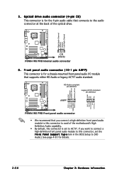
... motherboard's High Definition Audio capability. • By default, this connector, set to the audio connector at the back of the optical drive. ® P5W64 WS PRO Right Audio Channel Ground Ground Left Audio Channel AGND PRESENCE# SENSE1_RETUR SENSE2_RETUR ® P5W64 WS PRO AGND NC NC NC CD (black) P5W64 WS PRO ...P a n e l S u p p o r t T y p e item in the BIOS Setup to [HD Audio]. HD-Audio-compliant pin definition Legacy AC'97-compliant pin definition AAFP P5W64 WS PRO Front panel audio connector • We recommend that supports either HD Audio or legacy AC'97 audio standard.
... motherboard's High Definition Audio capability. • By default, this connector, set to the audio connector at the back of the optical drive. ® P5W64 WS PRO Right Audio Channel Ground Ground Left Audio Channel AGND PRESENCE# SENSE1_RETUR SENSE2_RETUR ® P5W64 WS PRO AGND NC NC NC CD (black) P5W64 WS PRO ...P a n e l S u p p o r t T y p e item in the BIOS Setup to [HD Audio]. HD-Audio-compliant pin definition Legacy AC'97-compliant pin definition AAFP P5W64 WS PRO Front panel audio connector • We recommend that supports either HD Audio or legacy AC'97 audio standard.
Motherboard Installation Guide
Page 61
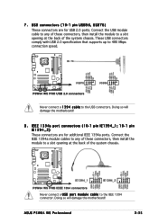
...P5W64 WS PRO USB+5V USB_P6USB_P6+ GND NC USB+5V USB_P8USB_P8+ GND NC USB+5V USB_P5USB_P5+ GND USB78 P5W64 WS PRO USB 2.0 connectors USB+5V USB_P7USB_P7+ GND USB56 Never connect a 1 3 9 4 c a b l e to the IEEE 1394 connector. Doing so will damage the motherboard! 8 . ASUS P5W64 WS Professional...+ GND TPB1+ +12V TPA2GND TPB2+12V GND IE1394_1 IE1394_2 TPA1GND TPB1+12V GND P5W64 WS PRO IEEE 1394 connectors Never connect a U S B p o r t m o d u l e c a b l e to the USB connectors. Doing so will damage the motherboard! I E E E 1 3 9 4a port connectors (10-1 pin IE1394_1 ...
...P5W64 WS PRO USB+5V USB_P6USB_P6+ GND NC USB+5V USB_P8USB_P8+ GND NC USB+5V USB_P5USB_P5+ GND USB78 P5W64 WS PRO USB 2.0 connectors USB+5V USB_P7USB_P7+ GND USB56 Never connect a 1 3 9 4 c a b l e to the IEEE 1394 connector. Doing so will damage the motherboard! 8 . ASUS P5W64 WS Professional...+ GND TPB1+ +12V TPA2GND TPB2+12V GND IE1394_1 IE1394_2 TPA1GND TPB1+12V GND P5W64 WS PRO IEEE 1394 connectors Never connect a U S B p o r t m o d u l e c a b l e to the USB connectors. Doing so will damage the motherboard! I E E E 1 3 9 4a port connectors (10-1 pin IE1394_1 ...
Motherboard Installation Guide
Page 63
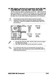
... GND +12V Rotation P5W64 WS PRO Fan connectors • Only the CPU_FAN, CHA_FAN1, and CHA_FAN2 connectors support the ASUS Q-Fan 2 feature. • CHA_FAN1 and CHA_FAN2 use the same Q-Fan 2 controller. 10. Do not forget to connect the fan cables to the motherboard connector labeled CHA_FAN1 for better thermal environment. These are not jumpers! ASUS P5W64 WS Professional 2-37 If...
... GND +12V Rotation P5W64 WS PRO Fan connectors • Only the CPU_FAN, CHA_FAN1, and CHA_FAN2 connectors support the ASUS Q-Fan 2 feature. • CHA_FAN1 and CHA_FAN2 use the same Q-Fan 2 controller. 10. Do not forget to connect the fan cables to the motherboard connector labeled CHA_FAN1 for better thermal environment. These are not jumpers! ASUS P5W64 WS Professional 2-37 If...
Motherboard Installation Guide
Page 79
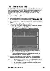
...utility The ASUS EZ Flash 2 feature allows you to update the BIOS without having to go through the long process of booting from a floppy disk and using EZ Flash 2: 1. ASUSTek EZ Flash 2 BIOS ROM Utility V3.00 FLASH TYPE: Winbond W39V080A 8Mb LPC Current ROM BOARD: P5W64-WS Pro VER: ...disk drive or the USB port. Then press . 4. Visit the ASUS website (www.asus.com) to download the latest BIOS file for the motherboard and rename the same to a floppy disk or a USB flash disk, then restart the system. 3. ASUS P5W64 WS Professional 4-5 To update the BIOS using a DOS-based utility. Save ...
...utility The ASUS EZ Flash 2 feature allows you to update the BIOS without having to go through the long process of booting from a floppy disk and using EZ Flash 2: 1. ASUSTek EZ Flash 2 BIOS ROM Utility V3.00 FLASH TYPE: Winbond W39V080A 8Mb LPC Current ROM BOARD: P5W64-WS Pro VER: ...disk drive or the USB port. Then press . 4. Visit the ASUS website (www.asus.com) to download the latest BIOS file for the motherboard and rename the same to a floppy disk or a USB flash disk, then restart the system. 3. ASUS P5W64 WS Professional 4-5 To update the BIOS using a DOS-based utility. Save ...

Motherboard Installation Guide
Page 163
... 4. Place the motherboard support CD in Windows® environment. Press any key when prompted to boot from CD. The following message appears on screen. When finished, select the type of RAID driver disk you want to format the floppy disk. ASUS P5W64 WS Professional 5-39 Press to ... BIOS Setup. 3. Restart the computer. 5. The Makedisk menu appears. 1) Intel ICH7R RAID/AHCI Driver Page 2) Marvell 88SE6141 SATA Driver for P5WDG2 WS PRO Page 3) Marvell 88SE6145 SATA RAID Driver for drive B:\ and press ENTER when ready... 7. 5.5 Creating a RAID driver disk A floppy disk with ...
... 4. Place the motherboard support CD in Windows® environment. Press any key when prompted to boot from CD. The following message appears on screen. When finished, select the type of RAID driver disk you want to format the floppy disk. ASUS P5W64 WS Professional 5-39 Press to ... BIOS Setup. 3. Restart the computer. 5. The Makedisk menu appears. 1) Intel ICH7R RAID/AHCI Driver Page 2) Marvell 88SE6141 SATA Driver for P5WDG2 WS PRO Page 3) Marvell 88SE6145 SATA RAID Driver for drive B:\ and press ENTER when ready... 7. 5.5 Creating a RAID driver disk A floppy disk with ...

P5W64 WS Professional English Edition User's Manual
Page 17
... the following items. Motherboard I/O modules Cables Accessories Application CD Documentation ASUS P5W64 WS PRO motherboard 1 x 2-port IEEE 1394a module 1 x 2-port USB 2.0 module 1 x Floppy disk drive cable 1 x Ultra DMA 133/100/66 cable 7 x Serial ATA signal cables 4 x Serial ATA power cables for buying an ASUS® P5W64 WS Professional Workstation motherboard! ASUS P5W64 WS Professional 1-1 1.1 Welcome! Before you for up to 7 devices I/O shield ASUS motherboard support CD InterVideo...
... the following items. Motherboard I/O modules Cables Accessories Application CD Documentation ASUS P5W64 WS PRO motherboard 1 x 2-port IEEE 1394a module 1 x 2-port USB 2.0 module 1 x Floppy disk drive cable 1 x Ultra DMA 133/100/66 cable 7 x Serial ATA signal cables 4 x Serial ATA power cables for buying an ASUS® P5W64 WS Professional Workstation motherboard! ASUS P5W64 WS Professional 1-1 1.1 Welcome! Before you for up to 7 devices I/O shield ASUS motherboard support CD InterVideo...

P5W64 WS Professional English Edition User's Manual
Page 27
... power LED. 2.1 Before you proceed Take note of the onboard LED. ® P5W64 WS PRO SB_PWR ON Standby Power P5W64 WS PRO Onboard LED OFF Powered Off ASUS P5W64 WS Professional 2-1 The illustration below shows the location of the following precautions before you install motherboard components or change any motherboard settings. • Unplug the power cord from the wall socket before touching...
... power LED. 2.1 Before you proceed Take note of the onboard LED. ® P5W64 WS PRO SB_PWR ON Standby Power P5W64 WS PRO Onboard LED OFF Powered Off ASUS P5W64 WS Professional 2-1 The illustration below shows the location of the following precautions before you install motherboard components or change any motherboard settings. • Unplug the power cord from the wall socket before touching...

P5W64 WS Professional English Edition User's Manual
Page 28
... the chassis. The edge with external ports goes to ensure that you install the motherboard, study the configuration of the chassis ® P5W64 WS PRO 2-2 Chapter 2: Hardware information Place this side towards the rear of your chassis to the rear part of the chassis as indicated in the image below. 2.2.2 ...
... the chassis. The edge with external ports goes to ensure that you install the motherboard, study the configuration of the chassis ® P5W64 WS PRO 2-2 Chapter 2: Hardware information Place this side towards the rear of your chassis to the rear part of the chassis as indicated in the image below. 2.2.2 ...

P5W64 WS Professional English Edition User's Manual
Page 30
30.5cm (12.0in) 2.2.4 Motherboard layout 24.5cm (9.6in) PS/2KBMS T: Mouse B: Keyboard SPDIF_O1 SPDIF_O2 EATX12V LGA775 CPU_FAN PWR_FAN Super I/O ESATA PARALLEL PORT FLOPPY DDR2 DIMM_B1 (64 bit,240-pin module) DDR2 DIMM_B2 (64 bit,240-pin module) ® P5W64 WS PRO DDR2 DIMM_A1 (64 bit,240-pin module) DDR2 DIMM_A2 (64 bit,240-pin...
30.5cm (12.0in) 2.2.4 Motherboard layout 24.5cm (9.6in) PS/2KBMS T: Mouse B: Keyboard SPDIF_O1 SPDIF_O2 EATX12V LGA775 CPU_FAN PWR_FAN Super I/O ESATA PARALLEL PORT FLOPPY DDR2 DIMM_B1 (64 bit,240-pin module) DDR2 DIMM_B2 (64 bit,240-pin module) ® P5W64 WS PRO DDR2 DIMM_A1 (64 bit,240-pin module) DDR2 DIMM_A2 (64 bit,240-pin...

P5W64 WS Professional English Edition User's Manual
Page 34
... lever is released from the retention tab. Press the load lever with your thumb (A), then move it to the left (B) until it is on the motherboard. ® P5W64 WS PRO P5W64 WS PRO CPU Socket 775 Before installing the CPU, make sure that the socket box is facing towards you . Retention tab A Load lever PnP cap B This...
... lever is released from the retention tab. Press the load lever with your thumb (A), then move it to the left (B) until it is on the motherboard. ® P5W64 WS PRO P5W64 WS PRO CPU Socket 775 Before installing the CPU, make sure that the socket box is facing towards you . Retention tab A Load lever PnP cap B This...

P5W64 WS Professional English Edition User's Manual
Page 37
Push down two fasteners at a time in a diagonal sequence to the connector on the motherboard labeled CPU_FAN. Connect the CPU fan cable to secure the heatsink and fan assembly in place. Hardware monitoring errors can occur if you fail to connect the CPU fan connector! ASUS P5W64 WS Professional 2-11 A B A B A B B A 3. CPU_FAN ® P5W64 WS PRO CPU FAN PWM CPU FAN IN CPU FAN PWR GND P5W64 WS PRO CPU fan connector Do not forget to plug this connector. 2.
Push down two fasteners at a time in a diagonal sequence to the connector on the motherboard labeled CPU_FAN. Connect the CPU fan cable to secure the heatsink and fan assembly in place. Hardware monitoring errors can occur if you fail to connect the CPU fan connector! ASUS P5W64 WS Professional 2-11 A B A B A B B A 3. CPU_FAN ® P5W64 WS PRO CPU FAN PWM CPU FAN IN CPU FAN PWR GND P5W64 WS PRO CPU fan connector Do not forget to plug this connector. 2.

P5W64 WS Professional English Edition User's Manual
Page 40
...; P5W64 WS PRO DIMM_A1 DIMM_A2 DIMM_B1 DIMM_B2 P5W64 WS PRO 240-pin DDR2 DIMM sockets Channel Channel A Channel B Sockets DIMM_A1 and DIMM_A2 DIMM_B1 and DIMM_B2 2.4.2 Memory configurations You may detect less than 8 GB system memory when you obtain memory modules from the same vendor. 2.4 System memory 2.4.1 Overview The motherboard comes with the same CAS latency. Visit the ASUS...
...; P5W64 WS PRO DIMM_A1 DIMM_A2 DIMM_B1 DIMM_B2 P5W64 WS PRO 240-pin DDR2 DIMM sockets Channel Channel A Channel B Sockets DIMM_A1 and DIMM_A2 DIMM_B1 and DIMM_B2 2.4.2 Memory configurations You may detect less than 8 GB system memory when you obtain memory modules from the same vendor. 2.4 System memory 2.4.1 Overview The motherboard comes with the same CAS latency. Visit the ASUS...

