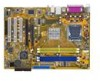
Motherboard Installation Guide
Page 13
This chapter describes the motherboard features and the new technologies it supports. 1Product introduction ASUS P5VDC-X 1-1
Motherboard Installation Guide
Page 14
...® Pentium® 4 processor in the long line of the above items is damaged or missing, contact your motherboard package for the following items. Motherboard ASUS P5VDC-X motherboard Cables 1 x Serial ATA cable 1 x Serial ATA power cable 1 x Ultra DMA 133/100/66 cable 1 x Floppy disk drive cable Accessories I/O shield Application CD... and frequency depending on it another standout in the 775-land package. 1.1 Welcome! Before you for details. 1-2 Chapter 1: Hardware information See page 1-8 for buying an ASUS® P5VDC-X motherboard!
Motherboard Installation Guide
Page 15
... PCI Express x4 speed outperforms PCI interface with the onboard LAN port. See page 1-29 for a thinner, lighter design without buying expensive additional LAN cards. ASUS P5VDC-X 1-3 Intel® 65nm dual-core processors utilize the latest package technologies for details. 10/100 Mbps LAN Easy connectivity to your network or broadband connection...
Motherboard Installation Guide
Page 17
... soft-off or the power cord is detached from the power supply. Top:Line In Center:Line Out Below:Mic In P5VDC-X R P5VDC-X Onboard LED SB_PWR ON Standby Power OFF Powered Off ASUS P5VDC-X 1-5 This is a reminder that you should shut down the system and unplug the power cable before handling components to avoid...
Motherboard Installation Guide
Page 21
...; angle (A), then push the PnP cap from the retention tab. The socket alignment keys should face you are installing a CPU. 3. Alignment key Gold triangle mark ASUS P5VDC-X 1-9 2. Lift the load lever in the direction of the cam box should fit into the CPU notches. Position the CPU on the socket, making sure...
Motherboard Installation Guide
Page 23
... that the four fasteners match the holes on the motherboard. Narrow end of the groove pointing outward. (The photo shows the groove shaded for emphasis.) ASUS P5VDC-X 1-11 Orient the heatsink and fan assembly such that the CPU fan cable is closest to orient each fastener with the narrow end of the...
Motherboard Installation Guide
Page 25
Rotate each fastener counterclockwise. 3. B A B B A ASUS P5VDC-X 1-13 Pull up two fasteners at a time in a diagonal sequence to disengage the heatsink B and fan assembly from the connector on the motherboard. 2. 1.6.3 Uninstalling the CPU heatsink and fan To uninstall the CPU heatsink and fan: 1. Disconnect the CPU fan cable from the A A motherboard.
Motherboard Installation Guide
Page 27
...512 MB and 1 GB unbuffered non-ECC DDR/DDR2 DIMMs into the DIMM sockets using the memory configurations in DDR DIMM sockets. ASUS P5VDC-X 1-15 The following figure illustrates the location of the sockets: Color Blue Yellow Sockets DDR_1 and DDR_2 DDR2_1 and DDR2_2 Top:Line ...In Center:Line Out Below:Mic In P5VDC-X R DDR2_B1 DDR2_A1 DDR_B1 DDR_A1 P5VDC-X DDR & DDR2 DIMM Sockets • To prevent damage to the motherboard, do not use DDR and DDR2 memory simultaneously. •...
Motherboard Installation Guide
Page 29
... latest DDR2-533, DDR-400, or DDR-333 Qualified Vendors List. supports one pair of modules inserted into both of the blue slots. ASUS P5VDC-X 1-17 B -
Motherboard Installation Guide
Page 31
... supply before inserting or removing DIMMs or other system components. Align a DIMM on 1 the socket. 3. To install a DDR2 DIMM: 1. Remove the DIMM from the socket. ASUS P5VDC-X 1-19 Unlock a DDR2 DIMM socket by pressing the retaining clips outward. 2. Simultaneously press the retaining clips outward to 2 unlock the DIMM.
Motherboard Installation Guide
Page 33
shared - - - - - - - - shared - - - - - - - - otherwise, conflicts will arise between the two PCI groups, making the system unstable and the card inoperable. ASUS P5VDC-X 1-21 shared shared - - - - - - - - shared - - - - - shared - - - - - - - - - - - - shared - - - - - - shared - - - - - - shared - - - - - - - - shared - - - - - - - - 1.8.3 Interrupt assignments Standard interrupt assignments IRQ Priority 0 1 1 2 2 - 3 11 4 12 5 13 6 14 7 15 8 3 9 4 10 5 11 6 12 7 13 8 ...
Motherboard Installation Guide
Page 35
.... V1.00 Rev. B • Some PCI Express graphics cards cannot operate on PCIe x4 mode. • Visit the ASUS website for the latest VGA Qualified Vendors List. ASUS P5VDC-X 1-23 V1.00 Rev. V1.00 Rev. V1.00A Rev.1.02 Rev. V1.00 Rev. V1.03 Rev. V1....00 Rev. V1.01 Rev. VGA Qualified Vendors List (PCIe x4 mode) PCIe X 16 VGA Card ASUS EAX300 ASUS EAX300SE/T ASUS EAX300SE/TD ASUS EAX600 Pro ASUS EAX600XT ASUS EAX600XT/TD ASUS EAX700 ASUS EAX700-X/TD ASUS EAX8002DTV ASUS EAX800 Pro ASUS...
Motherboard Installation Guide
Page 37
... total current consumed must NOT exceed the power supply capability (+5VSB) whether under normal condition or in low power mode) using the connected USB devices. ASUS P5VDC-X 1-25 The USBPW56 and USBPW78 jumpers are for each USB port; otherwise, the system would not power up feature requires a power supply that you can...
Motherboard Installation Guide
Page 39
... disk drive (FDD) signal cable. Insert one end of the floppy disk drive. This port is for a PS/2 keyboard. 1.10.2 Internal connectors 1. P5VDC-X Floppy Disk Drive Connector ASUS P5VDC-X 1-27 USB 2.0 ports 3 and 4. This 9-pin COM1 port is removed to PIN 1. Pin 5 on the floppy ribbon cable to prevent incorrect cable connection...
Motherboard Installation Guide
Page 41
ASUS P5VDC-X 1-29 For detailed instructions on how to configure RAID 0,RAID 1, and JBOD, refer to the RAID manual in the support CD. GND RSATA_TXP1 RSATA_TXN1 GND RSATA_RXP1 RSATA_RXN1 GND Top:Line In Center:Line Out Below:Mic In P5VDC-X R SATA1 SATA2 GND RSATA_RXN2 RSATA_RXP2 GND RSATA_TXN2 RSATA_TXN2 GND P5VDC-X SATA Connectors Install...
Motherboard Installation Guide
Page 43
... out_L NC Line out_R MIC2_R MIC2_L PORT2 L SENSE_SEND PORT2 R PORT1 R PORT1 L AAFP NC NC NC AGND SENSE2_RETUR SENSE1_RETUR PRESENCE# GND P5VDC-X Analog Front Panel Connector It is recommended that supports up to 480 Mbps connection speed. USB connectors (10-1 pin USB56, USB78_WIFI) These...install the module to avail of the system chassis. Front panel audio connector (10-1 pin AAFP) This connector is purchased separately. 6. ASUS P5VDC-X Analog Front Panel Connector 1-31 These USB connectors comply with USB 2.0 specification that you connect a high-definition front...
Motherboard Installation Guide
Page 45
Top:Line In Center:Line Out Below:Mic In P5VDC-X PLED SPEAKER PLED+ PLED+5V Ground Ground Speaker PANEL IDE_LED+ IDE_LED- Pressing the power button turns the system on or puts the system in sleep ... the system power LED. The speaker allows you turn on the BIOS settings. PWR Ground Reset Ground R IDE_LED P5VDC-X System Panel Connector Reset PWRSW The sytem panel connector is for the HDD Activity LED. ASUS P5VDC-X 1-33 9. Connect the chassis power LED cable to this connector. Pressing the power switch for more than...
Motherboard Installation Guide
Page 47
Detailed descriptions of the BIOS parameters are also provided. 2 BIOS setup ASUS P5VDC-X 2-1 This chapter tells how to change the system settings through the BIOS Setup menus.
Motherboard Installation Guide
Page 49
... found in the BIOS chip so it is accessible by pressing + during POST to P5VDC-X.ROM. ASUS P5VDC-X 2-3 Press , then follow screen instructions to a floppy disk, then restart the system. 3. Visit the ASUS website (www.asus.com) to prevent system boot failure! • A "Floppy not found ! When... EZFlash starting BIOS update Checking for the motherboard and rename the same to the floppy disk drive. d. Floppy found !" A "P5VDC-X.ROM not found , EZ Flash performs the BIOS update process and automatically reboots the system when done. The EZ Flash utility is built-in...
Motherboard Installation Guide
Page 51
...;es the file and starts updating the BIOS. Version 1.10 Copyright (C) 2002 American Megatrends, Inc. Version 1.10 Copyright (C) 2002 American Megatrends, Inc. Visit the ASUS website (www.asus.com) and download the latest BIOS file for the motherboard. done A:\> ASUS P5VDC-X 2-5